

Page 1

User Guide
English
399Z1R557B
Dolev
800V+/800V
www.creo.com
2
/800V
3
Page 2

Page 3

Dolev 800V+/800V
User Guide
2
/800V
3
Page 4

Page 5

Copyright
Trademarks
Copyright © 2003 Creo Inc. All rights reserved.
No copying, distribution, publication, modification, or incorporation of this document, in whole or part, is
permitted without the express written permission of Creo. In the event of any permitted copying, distribution,
publication, modification, or incorporation of this document, no changes in or deletion of author attribution,
trademark legend, or copyright notice shall be made.
No part of this document may be reproduced, stored in a retrieval system, published, used for commercial
exploitation, or transmitted, in any form by any means, electronic, mechanical, photocopying, recording, or
otherwise, without the express written permission of Creo Inc.
This document is also distributed in Adobe Systems Incorporated's PDF (Portable Document Format). You may
reproduce the document from the PDF file for internal use. Copies produced from the PDF file must be
reproduced in whole.
. . . . . . . . . . . . . . . . . . . . . . . . . . . . . . . . . . . . . . . . . . . . . . . . . . . . . . . . . . . . . . . . . . . . . . . . . . . . . . . . . . . . . . . . . . . . . . . . . . . .
The Creo wordmark, Creo logo, and the names of the Creo products and services referred to in this document are
trademarks of Creo Inc.
Adobe, Acrobat, and the Acrobat logo are registered trademarks of Adobe Systems Incorporated, and are
registered in the U.S. Patents and Trademark Office and may be registered in other jurisdictions.
Apple, AppleTalk, AppleShare, EtherTalk, LocalTalk, Macintosh, and LaserWriter are trademarks of Apple
Computer, Inc.
Microsoft, Windows, Windows 2000, and Windows NT are trademarks or registered trademarks of Microsoft
Corp.
Xerox is a registered trademark of Xerox Corp.
Other brand or product names are the trademarks or registered trademarks of their respective owners.
. . . . . . . . . . . . . . . . . . . . . . . . . . . . . . . . . . . . . . . . . . . . . . . . . . . . . . . . . . . . . . . . . . . . . . . . . . . . . . . . . . . . . . . . . . . . . . . . . . . .
FCC Compliance
The Creo equipment referred to in this document complies with the requirements in Part 15 of FCC Rules for a
Class A computing device. Operation of the Creo equipment in a residential area may cause unacceptable
interference to radio and TV reception, requiring the operator to take whatever steps are necessary to correct the
interference.
. . . . . . . . . . . . . . . . . . . . . . . . . . . . . . . . . . . . . . . . . . . . . . . . . . . . . . . . . . . . . . . . . . . . . . . . . . . . . . . . . . . . . . . . . . . . . . . . . . . .
Limitation of Liability
The product, software or services are being provided on an "as is" and "as available" basis. Except as may be stated
specifically in your contract, Creo Inc. expressly disclaims all warranties of any kind, whether express or implied,
including, but not limited to, any implied warranties of merchantability, fitness for a particular purpose and noninfringement.
You understand and agree that Creo Inc. shall not be liable for any direct, indirect, incidental, special,
consequential or exemplary damages, including but not limited to, damages for loss of profits, goodwill, use, data
or other intangible losses (even if Creo has been advised of the possibility of such damages), resulting from: (i)
the use or the inability to use the product or software; (ii) the cost of procurement of substitute goods and
services resulting from any products, goods, data, software, information or services purchased; (iii) unauthorized
access to or alteration of your products, software or data; (iv) statements or conduct of any third party; (v) any
other matter relating to the product, software, or services.
Page 6

Patents
The text and drawings herein are for illustration and reference only. The specifications on which they are based
are subject to change. Creo Inc. may, at any time and without notice, make changes to this document. Creo Inc.,
for itself and on behalf of its subsidiaries, assumes no liability for technical or editorial errors or omissions made
herein, and shall not be liable for incidental, consequential, indirect, or special damages, including, without
limitation, loss of use, loss or alteration of data, delays, or lost profits or savings arising from the use of this
document.
.. . . . . . . . . . . . . . . . . . . . . . . . . . . . . . . . . . . . . . . . . . . . . . . . . . . . . . . . . . . . . . . . . . . . . . . . . . . . . . . . . . . . . . . . . . . . . . . . . . . .
This product is covered by one or more of the following U.S. patents:
RE37,376
4,558,302
4,743,091
4,992,864
5,049,901
5,079,721
5,103,407
5,111,308
5,113,249
5,122,871
5,124,547
5,132,723
5,150,225
5,153,769
5,155,782
5,157,516
5,208,818
5,208,888
5,247,174
5,249,067
5,283,140
5,291,273
5,323,248
.. . . . . . . . . . . . . . . . . . . . . . . . . . . . . . . . . . . . . . . . . . . . . . . . . . . . . . . . . . . . . . . . . . . . . . . . . . . . . . . . . . . . . . . . . . . . . . . . . . . .
Creo Inc.
3700 Gilmore Way
Burnaby, B.C., Canada
V5G 4M1
Tel: 1-604-451-2700
Fax: 1-604-437-9891
http://www.creo.com
399Z1R557B
Revised September 2003
5,325,217
5,339,176
5,343,059
5,355,446
5,359,451
5,359,458
5,367,360
5,384,648
5,384,899
5,412,491
5,412,737
5,420,702
5,420,722
5,459,505
5,473,733
5,481,379
5,488,906
5,497,252
5,508,828
5,509,561
5,517,359
5,519,852
5,526,143
5,532,728
5,561,691
5,568,595
5,576,754
5,579,115
5,592,309
5,594,556
5,600,448
5,608,822
5,615,282
5,625,766
5,636,330
5,649,220
5,650,076
5,652,804
5,680,129
5,691,823
5,691,828
5,696,393
5,699,174
5,699,740
5,708,736
5,713,287
5,742,743
5,764,374
5,764,381
5,771,794
5,785,309
5,813,346
5,818,498
5,854,883
5,861,904
5,861,992
5,875,288
5,894,342
5,900,981
5,934,196
5,942,137
5,946,426
5,947,028
5,958,647
5,966,504
5,969,872
5,973,801
5,986,819
5,995,475
5,996,499
5,998,067
6,003,442
6,014,471
6,016,752
6,031,932
6,043,865
6,060,208
6,063,528
6,063,546
6,072,518
6,090,529
6,096,461
6,098,544
6,107,011
6,112,663
6,115,056
6,121,996
6,130,702
6,134,393
6,136,509
6,137,580
6,147,789
6,158,345
6,159,659
6,164,637
6,180,325
6,181,362
6,181,439
6,186,068
6,189,452
6,191,882
6,204,874
6,208,369
6,214,276
6,217,965
6,260,482
6,266,080
6,266,134
6,267,054
6,268,948
6,283,589
6,295,076
6,299,572
6,318,266
6,352,816
6,353,216
6,366,339
6,371,026
6,377,739
6,387,597
6,396,422
6,396,618
6,407,849
6,414,755
6,422,801
6,435,091
6,441,914
6,450,092
6,456,396
6,476,931
6,477,955
6,509,903
Page 7

Contents
Using This Manual vii
Who Should Use This Manual ................................................................................................................. viii
1 Safety Precautions 1
Installation Safety Precautions................................................................................................................... 2
General Safety Precautions ....................................................................................................................... 2
Disconnection from the Mains Supply ................................................................................................ 2
Lithium Battery .................................................................................................................................. 2
Maintenance ..................................................................................................................................... 3
Safety Interlocks ................................................................................................................................ 3
Laser Safety Precautions ........................................................................................................................... 4
Warning Labels......................................................................................................................................... 6
2 Introduction to Dolev 800V+/800V2/800V
Introduction to the Imagesetter .............................................................................................................. 14
Imagesetter Front View........................................................................................................................... 15
Imagesetter Rear View............................................................................................................................ 18
Startup ................................................................................................................................................... 20
Shutdown .............................................................................................................................................. 20
Reset Button........................................................................................................................................... 21
Control Panel ......................................................................................................................................... 21
LCD Screen...................................................................................................................................... 22
Soft Buttons and Soft Functions....................................................................................................... 24
Main Screen Soft Functions.............................................................................................................. 25
Specifications ......................................................................................................................................... 28
3
13
3 Media Management 35
Overview ................................................................................................................................................ 36
The Supply Cassettes .............................................................................................................................. 38
Using Two Large Cassettes .............................................................................................................. 38
Unloading the Supply Cassette ........................................................................................................ 39
Mounting Media onto the Supply Cassette ...................................................................................... 40
Loading the Supply Cassette into the Imagesetter ............................................................................ 43
Set Loading (Automatic Media Loading) ................................................................................................. 45
Performing Set Loading via the Control Panel .................................................................................. 45
Cassette Sign In ............................................................................................................................... 46
The Output Cassette............................................................................................................................... 48
Unloading the Output Cassette........................................................................................................ 48
Developing Film with Off-line Processor ........................................................................................... 49
Developing Film (In-line Processor) ................................................................................................... 50
Page 8

vi Dolev 800V+/800V2/800V3 User Guide
The Punch System .................................................................................................................................. 50
Punch System Design and Operation ...............................................................................................51
Punch Calibration ............................................................................................................................ 52
Defining Punch Parameters.............................................................................................................. 53
Removing Stuck Film from the Imagesetter............................................................................................. 56
4 Res-Intensity Calibration 57
Dolev 800V+/800V2/800V3 Calibration Workflow.................................................................................. 58
Film Specifications .................................................................................................................................. 59
Imaging .......................................................................................................................................... 59
Chemistry........................................................................................................................................ 60
Film Handling .................................................................................................................................. 60
Dimensions...................................................................................................................................... 61
Preparing Exposure Strips ....................................................................................................................... 61
Exposing the Strips ................................................................................................................................. 64
Measuring the Density on the Exposed Strips.......................................................................................... 64
Recording New Laser Intensity Values ..................................................................................................... 64
5 Data Configuration Setting 67
Data Connectivity................................................................................................................................... 68
Using TSP Data Cable Link (Data Connectivity)................................................................................. 69
Accessing the Output Device Configuration............................................................................................ 70
The Output Device Handling Window.............................................................................................. 70
Configuring the Dolev 800V+/800V
2
/800V3 Imagesetters....................................................................... 74
Index 79
Page 9

Using This Manual
Who Should Use This Manual ...........................................................viii
Page 10

viii Using This Manual
Who Should Use This Manual
This guide describes the options available with the Dolev® 800V3/800V4
imagesetter. The Dolev 800V+/800V
2
/800V3 imagesetter is a high-speed
large-format internal drum output device. The large exposure format is
convenient for tradeshops and printers. In addition, the Dolev 800V+/
2
800V
/800V3 imagesetter supports the preparation of plate-ready
separation films using the Creo Imposition feature.
Chapter 1, Safety Precautions warns against laser, mechanical and
electrical hazards.
Chapter 2, Introduction to Dolev 800V+/800V2/800V
3
, introduces the
imagesetter, and explains the start up and shut down procedures.
These are followed by the Control Panel description, and the imagesetter
specifications.
Chapter 3, Media Management, explains how to unload the supply
cassette, load film into it, and load it back into the imagesetter.
The following sections explain the media setup functions, how the media
is exposed, ejected into the output cassette and developed, and the last
section explains how to remove stuck media.
Chapter 4, Res-Intensity Calibration, explains how to guarantee high
quality exposures using a unique laser intensity for each plotting
resolution.
Chapter 5, Data Configuration Setting, explains how to configure the
imagesetter with the Brisque.
For further technical information refer to the Dolev 800V+/800V2/800V
Installation Guide, 399Z1R556B.
For further information on error messages refer to the Dolev 800V+/800V
3
800V
Troubleshooting Guide, 653-00095B.
3
2
/
Page 11

Safety Precautions
Read this chapter carefully before installing, operating, or
maintaining the Dolev 800V+/800V
Installation Safety Precautions .............................................................2
General Safety Precautions..................................................................2
Laser Safety Precautions......................................................................4
Warning Labels ...................................................................................6
2
/800V3 imagesetter.
Page 12

2 Chapter 1 – Safety Precautions
Installation Safety Precautions
WARNING: Installation must be done by authorized service personnel only.
WARNING: To avoid the risk of fire, no connections to the supply are to be made
before the service engineer sets the line voltage selector!
General Safety Precautions
Disconnection from the Mains Supply
Dolev 800V+/800V2/800V3 is equipped with a Master circuit breaker,
located at the lower rear part of the imagesetter, and an
located near the Control Panel at the front part of the imagesetter.
On/Off switch,
Lithium Battery
To achieve complete disconnection from the mains supply, the
circuit breaker
WARNING: Switching off only the On/Off switch leaves several circuits of the
imagesetter energized.
must be disconnected (switched to 0 position).
Master
The Dolev 800V+/800V2/800V3 contains a Lithium battery in the CPU
board.
The battery should be replaced by qualified service personnel. The battery
must not to be replaced by the user.
DANGER: Danger of explosion if battery is incorrectly replaced.
Page 13
General Safety Precautions 3
Maintenance
The Dolev 800V+/800V2/800V3 imagesetter is installed and serviced
exclusively by specialized technicians trained in the proper procedures for
working with and adjusting the laser beam power and its optical path.
You are allowed to perform only one (1) maintenance procedure, that is, to
remove film (supply media) stuck on the inside of the imagesetter drum
area. For details, please refer to Chapter 3, Media Management, Removing
Stuck Film from the Imagesetter.
Safety Interlocks
Upon opening a side door or taking out the loading assembly:
• Interlock switches are designed to disconnect power from the motors
and deacivate the laser.
• It may take up to 30 seconds for the spinner motor to halt after a door
is opened. Wait 30 seconds from the time the door is opened before
you dismantle the internal side protective barrier.
• You are forbidden, under any circumstances, to open covers that need a
screwdriver or any other tool to do so.
• Refrain from tampering with the electrical wiring inside the
imagesetter.
WARNING: Some wiring, located inside the electrical boxes, will remain
energized if the Master circuit breaker is not switched off.
• You are forbidden, under any circumstances, to defeat any of the
interlock switches.
While the Imagesetter is switched on and the interlocks are defeated:
• There is power present in the electrical, optical and mechanical
assemblies and inside the imagesetter.
DANGER: Electrical, laser and mechanical hazards exist!
Page 14

4 Chapter 1 – Safety Precautions
Laser Safety Precautions
WARNING: Even brief exposure of the eyes to the laser beam or its reflections
may cause permanent loss or permanent degradation of eyesight.
DANGER: Use of controls and/or adjustments, or performance of
procedures other than those specified in this manual may result in
hazardous radiation exposure.
Upon opening a side door or taking out the loading assembly:
• Interlock switches are designed to disconnect power from the motors
and deactivate the laser.
• You are forbidden, under any circumstances, to defeat any of the
interlock switches.
• You are forbidden, under any circumstances, to open covers that need a
screwdriver or any other tool to do so.
• Refrain from tampering with the electrical wiring inside the
imagesetter.
While the Imagesetter is switched on and the interlocks are defeated:
• There is power present in the electrical, optical and mechanical
assemblies and inside the imagesetter.
DANGER: Electrical, laser and mechanical hazards exist!
Page 15

Laser Safety Precautions 5
For Dolev 800V+/800V2/800V3 (see Figure 1 on page 9 and Figure 2 on
page 10):
• Up to 5 milliwatt of laser power at a wavelength of approx. 650 nm
may be present in the Output optical connector of the Static optics
assembly, Dynamic optics assembly, Optical fibers, Optical fibers
connectors, and on the inside of the imagesetter drum.
• Up to 10 milliwatt of laser power at the same wavelength may be
present inside the Static optics assembly.
WARNING: This laser radiation is hazardous to the eye and skin! Avoid exposure
to the beam and its reflections.
Page 16

6 Chapter 1 – Safety Precautions
Warning Labels
The following pages show the labels and their locations. Please notify Creo
service personnel if any of them are missing or damaged.
DANGER
LASER LIGHT WHEN OPEN AND INTERLOCK DEFEATED.
AVOID EXPOSURE TO BEAM.
K2G954
CAUTION:
HANDS OFF UNTIL
SPINNER MOTOR HAS RESTED!
WAIT 30 SECONDS AFTER
OPENING DOOR.
K2G955
DANGER
LASER LIGHT WHEN OPEN
AVOID EXPOSURE TO BEAM.
K2G956
LASER LIGHT WHEN OPEN
AVOID EXPOSURE TO BEAM.
DANGER
Page 17

Warning Labels 7
CLASS 1
LASER PRODUCT
EN60825, 21CFR 1040
K2G957
DANGER
LASER LIGHT WHEN
OPEN AND INTERLOCK
DEFEATED.
AVOID EXPOSURE
TO BEAM.
K2G958
SEE INSTALLATION
INSTRUCTIONS BEFORE
CONNECTING TO THE SUPPLY
K1F658
LASER LIGHT WHEN OPEN.
DANGER
K8F711
AVOID EXPOSURE TO BEAM
Page 18
8 Chapter 1 – Safety Precautions
DANGER
LASER LIGHT CONDUCTED
THROUGH OPTICAL FIBERS.
AVOID EXPOSURE TO BEAM.
K8F712
374A30170A
Electrical hazard!
Choc electrique!
Elektroschockgefahr!
374A7B951 (374A30170)
374A2G961
Page 19
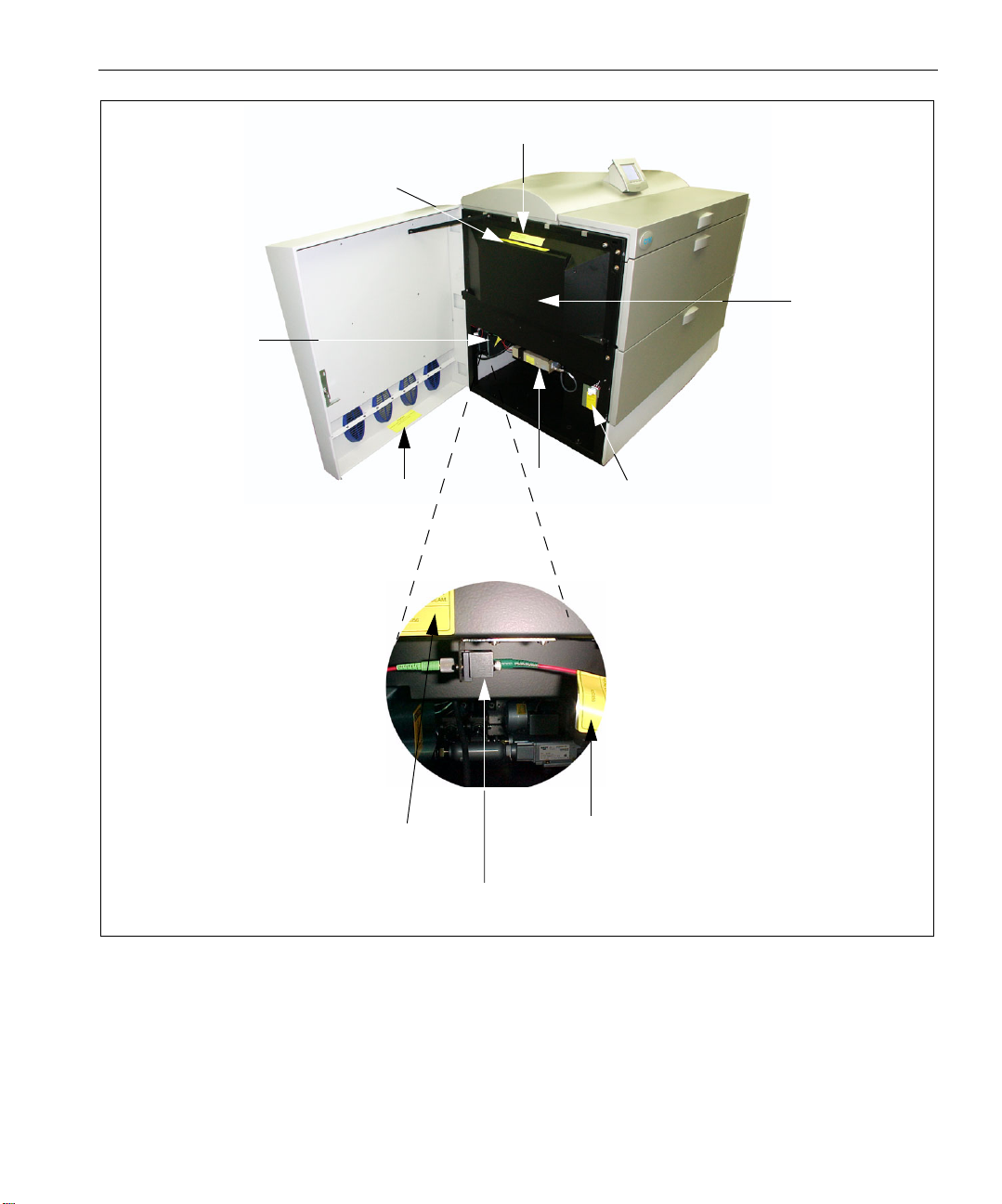
Warning Labels 9
K2G955
K8F711
Internal Side
K2G956
(attached on
the fiber of static optic,
near optical connector)
Protective Barrier
K2G954
K2G956
Fiber connector locker
290F7B8685
K2G956
K2G956
K2G958
Figure 1: Dolev 800V3 - left side door open
Page 20

10 Chapter 1 – Safety Precautions
K2G955
K8F711
K2G958
374A7B951
(374A30170)
K2G954
Figure 2: Right side door open
K8F711
(same on left side)
Figure 3: Right side, internal protective barrier removed
Page 21

Warning Labels 11
Figure 4: Rear view
K1F658
K2G957
Page 22

Page 23

Introduction to
2
Dolev 800V+/800V
/
3
800V
Introduction to the Imagesetter.........................................................14
Imagesetter Front View .....................................................................15
Imagesetter Rear View ......................................................................18
Startup .............................................................................................20
Shutdown.........................................................................................20
Reset Button .....................................................................................21
Control Panel....................................................................................21
Specifications....................................................................................28
Page 24

14 Chapter 2 – Introduction to Dolev 800V+/800V2/800V
Introduction to the Imagesetter
3
The imagesetter uses laser optics to output onto film or polyester plates.
Dolev 800V+/800V
2
/800V3 does not require computer experience to
operate. During normal use, once exposure starts, there is no need for
operator intervention since all functions are performed automatically.
The Dolev 800V+/800V
2
/800V3 handles high-volume film output of color
and black-and-white pages of text and graphics, and processes this data to
produce high-quality film output.
Media can be exposed in single or multiple runs continuously, without
operator intervention.
Procedures for film exposure are controlled by the Dolev 800V+/800V
3
micro controller.
800V
2
/
A punch option allows you to define customized registration marks. This
function is especially important when preparing film for impositioning.
The film is automatically cut, exposed and unloaded into a removable
output cassette. At the completion of a work session, the cassette is taken to
a film processor for development. An optional internal conveyor and inline
processor can be used for continuous film development.
The Dolev 800V+/800V
2
/800V3 changes the way images for plateimposition are prepared. Instead of using time consuming step-and-repeat
machines, Dolev 800V+/800V
2
/800V3 prepares plate-ready separation
films to copy directly to plate. Files are transferred from the workstation to
the imagesetter and exposed to the film. The film is then transferred to the
plate department.
Page 25

Imagesetter Front View 15
Imagesetter Front View
[4]
[2]
[5]
[3]
[1]
[6]
[7]
Figure 5: Dolev 800V+/800V2/800V3 Front View
[1] - Left service door
This door allows access to the Drum area. You may open this door to clear
media stuck in the drum area. Service engineers access the electronics and
optomechanics via the service doors.
[2] - Supply cassette compartment door
The small and medium supply cassettes are loaded via this door.
[3] - Large cassette door
The large supply cassette is loaded via this outer door.
Note: Another inner door is located behind this outer door.
Page 26

16 Chapter 2 – Introduction to Dolev 800V+/800V2/800V
[4] - Control Panel
Film loading and most basic operations are performed via the Control
Panel. In addition, the
top of the Control Panel. The
Reset switch. The imagesetter is turned
Reset switch [a] is recessed behind the bezel at the
On/Off switch [b] is also located next to the
on/off using this switch.
3
[a]
Figure 6: Reset and On/Off Switches
[b]
[5] - Right service door
This door allows access to the Drum area. You may open this door to clear
media stuck in the drum area. Service engineers access the electronics and
optomechanics via the service doors.
[6] - Output cassette door
The output cassette is located behind this door. Exposure media can be
output either to the output cassette or to an in-line processor.
[7] - Adjustment legs
Four (4) adjustment legs are used to level the imagesetter. Before moving
the unit, unlock the legs.
Wheels
Four (4) wheels allow easy positioning of the imagesetter. Once the
machine is in place, the adjustment legs are locked into position and the
wheels are ineffective.
Page 27

Imagesetter Front View 17
Large supply cassette (#1)
This is a 34 inch wide cassette suitable for film widths from 10 to 34 inch in
one inch step intervals.
[B]
[A]
Figure 7: Dolev 800V+/800V2/800V3 Small and Medium Cassettes
[A] - Small supply cassette
This is a 12 inch wide cassette for film widths 10, 11 and 12 inch.
[B] - Medium supply cassette
This is a 20 inch wide cassette suitable for film widths from 10 to 20 inch in
one inch step intervals.
Page 28

18 Chapter 2 – Introduction to Dolev 800V+/800V2/800V
Imagesetter Rear View
[1]
3
[2]
[6]
[4]
[5]
Figure 8: Dolev 800V+/800V2/800V3 Rear View
[9]
[1]
[3]
[7]
[1] - Upper service panel
The panel is not removed.
[2] - In-line processor panel (not shown)
Remove the panel if you connect to the in-line processor.
[8]
[3] - Lower service panel
Use the panel to access the power distribution unit, and the vacuum
system.
[4] - Fan
The fan does not require maintenance. It does require that the imagesetter
be kept at least 70 cm. from the wall.
Page 29

Imagesetter Rear View 19
[5] - Punch system (optional) pressure inlet
[6] - Connection to in-line processor
The in-line processor is an option for the Dolev 800V+/800V2/800V3.
[7] - Power inlet
The power cord is connected here.
[8] - Master circuit breaker
If a power surge or some other electrical problem has shorted power to the
imagesetter, check the breaker.
[9] - Vacuum pump outlet
Outlet for vacuum pump.
Turbo Screening connection
The Turbo Screening board is connected via a host cable 30 meters long:
For Dolev 800V+/800V2 - between the E-Box (SOMC) and the TSP inside
the Brisque.
For Dolev 800V
Brisque.
For further information about Turbo Screening see the TSP Board Installation
Guide.
3
- between the E-box (MB-SOMC) and TSP 100 inside the
Page 30

20 Chapter 2 – Introduction to Dolev 800V+/800V2/800V
Startup
To start up the imagesetter:
1. Make sure that the Master circuit breaker ([9] in the Imagesetter rear
view above) is
Figure 9: Master circuit breaker
Press the On/Off switch on the Control Panel.
2.
UP.
3
Shutdown
Under normal conditions, leave the Dolev 800V+/800V2/800V3 working at
all times (you do
not need to turn off the power overnight).
If you intend to leave the imagesetter idle for 48 hours, turn off the
imagesetter:
¾ Press the On/Off switch to turn off the imagesetter.
Note: During normal operation, do not shut down the power using the Master
circuit breaker. In case a power surge or some other electrical problem has
shorted power to the imagesetter, the circuit breaker may shut down the
machine (that is, it will be in the DOWN position); to turn on the power, pull the
circuit breaker upwards.
Page 31

Reset Button 21
Reset Button
The Reset button is located on the right side of the Control Panel.
¾ In case of a software error (that is, when the Control Panel or the
imagesetter is
to resume work.
Note: Depressing the Reset button does not help in case of stuck media or
media out.
not responding to commands), depress the Reset button
Control Panel
The Dolev 800V+/800V2/800V3 sends the imagesetter options, status and
error messages to the Control Panel.
The Control Panel is located on the middle of the upper part of the
imagesetter.
[4]
[3]
[1]
[2]
Page 32

22 Chapter 2 – Introduction to Dolev 800V+/800V2/800V
The Control Panel contains the following:
[1] - LCD screen
[2] - 4 soft buttons
[3] - On/Off Switch
[4] - Reset Button
3
LCD Screen
For details on the
On/Off Switch and Reset Button, refer to the Startup,
Shutdown and Reset section on the previous page.
The LCD screen displays a variety of text (such as, messages) and graphical
representations (such as, icons, and imagesetter views) that inform you of
the current status of the imagesetter and of the cassettes.
In addition, it displays menus and windows through which you may
perform both basic and advanced operations related to the machine and to
the exposure media.
The LCD screen standby is shown below:
[1]
[2]
[4]
[3]
Page 33

Control Panel 23
The display on the LCD screen consists of the following areas:
[1] - Imagesetter Micro Version
[2] - Current Process (or Progress Indicator)
[3] - Status of Loading Cassette
[4] - Soft Functions
Current Process/Progress Indicator
This area (on the top left part of the screen) displays the name of the
process that is currently running, or the current state of the imagesetter.
The startup process includes 12 stages, some of which are indicated by
StartUp # (# specifying a number), while others are indicated by the name
of the task, for example,
STANDBY - appears when the imagesetter is ready to expose, i.e. film is
already loaded, and both the Loading and Unloading drawers are closed.
NOT READY - appears when the imagesetter is not ready to expose (for
example, film is not loaded or one of the drawers/doors is open).
Attach.
HostOnLine - appears when communication between the Host and the
imagesetter has been established (for example, at the beginning of the
expose process or after selecting Get Params from Plotter).
Progress Indicator
When the imagesetter is exposing, a Progress indicator is displayed in the
Current Process area.
The pie chart fills from 0% to 100% when the exposing is completed.
Imagesetter Micro Version
This area (on the top of the screen) displays the number and the date of the
imagesetter Micro software version that is currently installed on the
Imagesetter PC.
Page 34

24 Chapter 2 – Introduction to Dolev 800V+/800V2/800V
Status of Loading Cassette
This area (on the left side of the screen) displays three (3) bars that
represent the Loading cassettes.
Soft Buttons and Soft Functions
Four (4) soft Buttons are located below the LCD screen of the Control
Panel. Press the requested soft button to activate the function that is
indicated on the LCD screen directly above it.
3
Four (4) soft
Functions are indicated on the bottom part of the LCD screen.
Each soft function indicates the action that is activated when you press the
corresponding soft button below it.
Note: The functionality of a specific soft button is variable and depends on the
soft function that is currently indicated on the LCD screen.
¾ To return to the previous function, press the SHIFT + ESC soft buttons.
Page 35
Control Panel 25
Main Screen Soft Functions
In STANDBY state the soft buttons function as follows:
Press the soft
button
Abort
Status
Params
To...
Stop the current process
View system messages.
View the parameters of the last/current
exposure that the Host sent to the
Imagesetter.
Util
Perform various functions related to the
exposure media, and to get information on
the media.
Utilities
Set Loading
Use this option to automatically cut the section of the media that was
exposed to light, and dispose of it in the unloading cassette/inline
processor.
¾ Move the Cassette field to LRG, MED, or SML (the default), according
to the size of cassette currently used.
Note: If the machine does not work properly at 0 parameter, the engineer must
change it. To do this, go to: Tools > Operation > Setup > Factory Table >
Conveyor Delay Time.
Note: If you are using 2 large cassettes, toggle the field to LWR (lower) or UPR
(upper).
Update Cst Mode
Use this option to indicate whether you wish to use one or two large
cassettes.
Page 36

26 Chapter 2 – Introduction to Dolev 800V+/800V2/800V
After you select Update CasMode from the menu, the Update CasMode
form appears.
¾ Toggle the Large Csts Mode field to 1 cst (the default) for 1 large
cassette (together with one small cassette and one medium cassette), or
2 cst for 2 large cassettes.
to
Media Info
Use this option to set the parameters of the selected cassette. After you
select the Cassette from the menu, the
Media Info table appears:
3
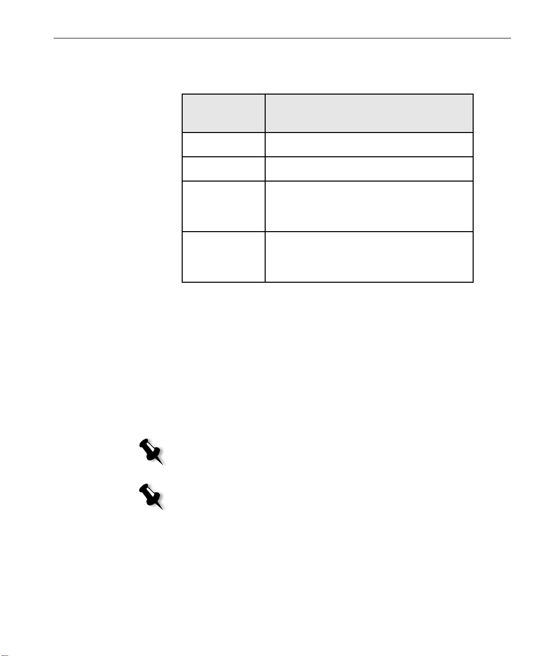
Parameter Range Default Do the following...
Current Length
0 - 61 61 The default (61 m) specifies that the loaded film is a full
roll. If you did not load a full roll of film, enter the
current length (in meters). This is the only field that
updates during exposure.
Material
Media
Thickness
Media Width
Res/Int Table #
Film, Plate,
Paper
Film Toggle this field to Film (the default), Plate, or Paper,
according to the media you loaded.
4 - 7 4 Toggle this field to 4 mil (the default) or to 7 mil,
according to the media you loaded.
254 - 838 304 Enter the width of the media you loaded.
- 1 Toggle this field to 1 (the default) to automatically select
a Res/Intensity table to suit the vendor (if such is
indicated in the Vendor field).
If the loaded film is not of the same type as the one
previously loaded, toggle this field to the appropriate
Res/Intensity table number.
Page 37

Control Panel 27
Parameter Range Default Do the following...
Full Length
Vendor
0 - 63 61 Enter the length of a full roll of film.
Note: If you loaded a full roll of film, this value is identical to
that of Current Length.
- None Toggle this field to None (the default) in order to use the
table specified in the Res/Int Table field.
Toggle this field to the name of the vendor of the loaded
media to use the Res/Int table that is specified in the
Res/Int Table # field. Note: If the Res/Int Table specifies
0, the system automatically selects a Res/Int table to suit
the specified vendor.
Mechanical Startup
This function will activate the mechanical start up procedure.
Use the function after opening one of the doors or if you want to set back
the machine to standby.
Active Task Operation
This function will show the parameters during the active task.
Slave Board Statuses
This function will show the status of the boards.
Messages
This function will show the messages from the machine.
Tools Operation
The tools operation are tools for service engineer.
Page 38

28 Chapter 2 – Introduction to Dolev 800V+/800V2/800V
Specifications
Tab le 1: Te c h n o l o g y
3
Structure
Dolev 800V+ Dolev 800V
Large-format,
Internal Drum
Large-format, Internal
Drum
2
Dolev 800V
Large-format,
Internal Drum
3
Light Source
Spot Size
Repeatability
Spinner
Raw Imaging Speed
@100 lpmm/ 2540 dpi
@ 80 lpmm/ 2032 dpi
@ 50 lpmm/ 1270 dpi
Laser Diode 650 nm
wavelength
Light Power 5
milliwatts
variable, 10-25
microns
±5µm οver the full
format of
successively imaged
films, disregarding
any distortion caused
by temperature,
humidity and film
material.
Air bearing up to
24,000 rpm
37.27 cm2/second
(346 in
89.3 cm
(831 in
2
/min)
2
/second
2
/min)
Laser Diode 650 nm
wavelength
Light Power 5
milliwatts
variable, 10-25
microns
±5µm over the full
format of successively
imaged films,
disregarding any
distortion caused by
temperature,
humidity and film
material.
Air bearing up to
45,000 rpm
2
/min)
2
/min)
2
/second (564
2
/second (882
60.7 cm
in
94.9 cm
in
Laser Diode 650 nm
wavelength
Light Power 5
milliwatts
variable, 10-25
microns
±5µm over the full
format of
successively imaged
films, disregarding
any distortion
caused by
temperature,
humidity and film
material.
Air bearing up to
45,000 rpm
4995 / 774
6283 / 974
10053 / 1558
Throughput
@100 lpmm/ 2540 dpi
@ 80 lpmm/ 2032 dpi
(full formats per
hour)
10 full formats/hr
(80 A4 pages/hr)
12 full formats/hr
(96 A4 pages/hr)
(full formats per
hour)
16.2 full formats/hr
(130 A4 pages/hr)
21.4 full formats/hr
(171 A4 pages/hr)
(full formats per
hour)
23 full formats/hr
27 full formats/hr
Page 39

Specifications 29
Tab le 1: Te c h n o l o g y
3
@ 50 lpmm/ 1270 dpi
Dolev 800V+ Dolev 800V
17 full formats/hr
(136 A4 pages/hr)
28.6 full formats/hr
(229 A4 pages/hr)
2
Dolev 800V
36 full formats/hr
Brisque
Table 2: Image Features
Maximum Net Image
Area
Page Formats
Capability
Press Formats
Capability
Resolution
TSP / VLSI TSP TSP 100
Dolev 800V+ Dolev 800V
838 x 1117 mm (33 x
44 in)
Up to 8*A4, 4*A3,
2*A2, 8*B4, 4*B3,
2*B2, 1*B1
Heidelberg GTO,
SM52, SM74, SM102
MAN Roland 100,
200. 600
Komori 26, 28, 44
50-200 pixels/mm,
1270-5080 dpi;
continuously
variable.
Optional lower and
higher resolutions
838 x 1117 mm (33 x
44 in)
Up to 8*A4, 4*A3,
2*A2, 8*B4, 4*B3,
2*B2, 1*B1
Heidelberg GTO,
SM52, SM74, SM102
MAN Roland 100,
200. 600
Komori 26, 28, 44
50-200 lpm, 12705080 dpi;
continuously
variable.
Up to 400 lpm
(10,000 dpi) for
security printing
models (UHR)
2
Dolev 800V
838 x 1117 mm (33 x
44 in)
Up to 8*A4, 4*A3,
2*A2, 8*B4, 4*B3,
2*B2, 1*B1
Heidelberg GTO,
SM52, SM74, SM102
MAN Roland 100,
200. 600
Komori 26, 28, 44
50-200 lpm, 12705080 dpi;
continuously
variable.
Up to 400 lpm
(10,000 dpi) for
security printing
models (UHR)
3
Screen Technology
Creo Turbo Screening
including
conventional dot
shapes: round,
square, diamond,
gravure. Creo
composite,
GeometricDOT and
FM.
Creo Turbo Screening
including
conventional dot
shapes: round,
square, diamond,
gravure. Creo
composite,
GeometricDOT and
FM.
Creo Turbo Screening
including
conventional dot
shapes: round,
square, diamond,
gravure. Creo
composite,
GeometricDOT and
FM.
Page 40

30 Chapter 2 – Introduction to Dolev 800V+/800V2/800V
Table 2: Image Features
3
Screen Ruling
Dolev 800V+ Dolev 800V
(frequency) 20-246
lpcm / 50-625 lpi
(frequency) 20-246
lpcm / 50-625 lpi
2
Dolev 800V
(frequency) 20-246
lpcm / 50-625 lpi
3
Screen Angles
User-selectable from
a variety of preset
angles.
Table 3: Media and Related Features
Dolev 800V+ Dolev 800V
Types of Media
Roll, medium to high
contrast, red sensitive,
film or polyester
plates
Media Width
254-863 mm in steps
of 25.4 mm 10–34 in.
in steps of 1 in
Media Length (inside
Drum)
Min. 420 mm (15 in);
Max. 1200 mm
(47 in)
Thickness and
Capacity
60 m/200 ft at
0.1 mm/4 mil
30 m/100 ft at
0.2mm/8 mil
User-selectable from
a variety of preset
angles.
2
Roll, medium to high
contrast, red sensitive,
film or polyester
plates
254-863 mm in steps
of 25.4 mm 10–34 in.
in steps of 1 in
Min. 450 mm (16 in);
Max. 1200 mm
(47 in)
60 m/200 ft at
0.1 mm/4 mil
30 m/100 ft at
0.2mm/8 mil
User-selectable from
a variety of preset
angles.
Dolev 800V
3
Roll, medium to
high contrast, red
sensitive, film or
polyester plates
254-863 mm in steps
of 25.4 mm 10–34 in.
in steps of 1 in
Min. 450 mm (16
in); Max. 1200 mm
(47 in)
60 m/200 ft at
0.1 mm/4 mil
30 m/100 ft at
0.2mm/8 mil
Page 41

Specifications 31
Table 3: Media and Related Features
3
Load/ Unload System
Dolev 800V+ Dolev 800V
Fully automatic from
three selectable
loading cassettes.
Vacuum film holddown. Dual unload
options: unload
cassette or inline
processor.
Fully automatic from
three selectable
loading cassettes.
Vacuum film holddown. Dual unload
options: unload
cassette or inline
processor.
2
Dolev 800V
Fully automatic from
three selectable
loading cassettes.
Vacuum film holddown. Dual unload
options: unload
cassette or inline
processor.
Loading Cassette
Unloading Cassette
Inline Processor
Punch System
Three different size
cassettes for rolls,
including daylight
film. Sizes up to:
304, 508, 863 mm
(12, 20, 34 in)
or
Two optional large
(863 mm/
34 in) cassettes
instead of three
cassettes.
One, accumulating
cut sheet type, 12
sheets capacity for
0.1 mm/4-mil film.
Optional (refer to
recommended list)
Customized head
punch up to
10 holes.
Optional, Bacher and
Stasser standard.
Three different size
cassettes for rolls,
including daylight
film. Sizes up to:
304, 508, 863 mm
(12, 20, 34 in)
or
Two optional large
(863 mm/
34 in) cassettes
instead of three
cassettes.
One, accumulating
cut sheet type, 12
sheets capacity for
0.1 mm/4-mil film.
Optional(refer to
recommended list)
Customized head
punch up to
10 holes.
Optional, Bacher and
Stasser standard.
Three different size
cassettes for rolls,
including daylight
film. Sizes up to:
304, 508, 863 mm
(12, 20, 34 in)
or
Two op ti o n a l l a r g e
(863 mm/
34 in) cassettes
instead of three
cassettes.
One, accumulating
cut sheet type, 12
sheets capacity for
0.1 mm/4-mil film.
Optional(refer to
recommended list)
Customized head
punch up to
10 holes.
Optional, Bacher
and Stasser standard.
Page 42

32 Chapter 2 – Introduction to Dolev 800V+/800V2/800V
Table 4: Environment
Dolev 800V+ Dolev 800V
2
Dolev 800V
3
3
Electrical
Requirements
Operating
Environment
Temperature:
Relative
Humidity:
Audible Noise:
Heat
Dissipatoin:
Area
Requirements
200/220/240 VAC, ±
10%
Europe: Single Phase,
50/60 Hz ± 2 Hz
USA/Japan: 2 Phase
50/60 Hz ± 2 Hz
Power
Less than 3 KVA
23°C ± 3°C
73.4°F ± 5.4°F
55% ± 5% RH
<55dbA
2500 BTU/hr
200/220/240 VAC, ±
10%
Europe: Single Phase,
50/60 Hz ± 2 Hz
USA/Japan: 2 Phase 50/
60 Hz ± 2 Hz
Power
Less than 3 KVA
23°C ± 3°C
73.4°F ± 5.4°F
55% ± 5% RH
<55dbA
2500 BTU/hr
200/220/240 VAC, ±
10%
Europe: Single Phase,
50/60 Hz ± 2 Hz
USA/Japan: 2 Phase 50/
60 Hz± 2 Hz
Power
Less than 3 KVA
23°C ± 3°C
73.4°F ± 5.4°F
55% ± 5% RH
<55dbA
2500 BTU/hr
6.7 square meters 6.7 square meters 6.7 square meters
Table 5: Physical Dimensions
Dolev 800V+ Dolev 800V
Dimensions
Height: 1230 mm
(48 in)
Width: 1650 mm
(65 in)
Depth: 1000 mm
(39 in)
Weight
550 kg (1210 lb) 550 kg (1210 lb) 550 kg (1210 lb)
2
Height: 1230 mm
(48 in)
Width: 1650 mm (65 in)
Depth: 1000 mm (39 in)
Dolev 800V
3
Height: 1230 mm
(48 in)
Width: 1650 mm
(65 in)
Depth: 1000 mm
(39 in)
Page 43

Specifications 33
Tab le 6: R I P
Dolev 800V+ Dolev 800V
2
Dolev 800V
3
Brisque
Processor: Power PC
604
Ty pe : Software
Operating System:
AIX
Architecture: CPSI
with composite
workflow and
Turbo Screening
CPU Speed: 332 MHz
and up
Interpreter: Postscript
Levels 2
and 3
DataFormats: PDF,
Postscript, EPS,
DCS1, DCS2, TIFF/
IT-PI, CopyDot
(scanned film),
(N)LW, CT, ICF
(Imposition Control
File), Brisque Page.
Communication
Formats:
Built-in Helios
EtherShare, NFS,
TCP/IP.
Processor: Power PC
604
Ty pe : Software
Operating System:
AIX
Architecture: CPSI
with composite
workflow and
Turbo Screening
CPU Speed: 332 MHz
and up
Interpreter: Postscript
Levels 2
and 3
DataFormats: PDF,
Postscript, EPS, DCS1,
DCS2, TIFF/IT-PI,
CopyDot (scanned
film), (N)LW, CT, ICF
(Imposition Control
File), Brisque Page.
Communication
Formats:
Built-in Helios
EtherShare, NFS, TCP/
IP.
Dual Processor: Power
PC 604
Ty pe : Software
Operating System:
AIX
Architecture: CPSI
with composite
workflow and
Turbo Screening
CPU Speed: 332 MHz
and up
Interpreter: Postscript
Levels 2
and 3
DataFormats: PDF,
Postscript, EPS,
DCS1, DCS2, TIFF/
IT-PI, CopyDot
(scanned film),
(N)LW, CT, ICF
(Imposition Control
File), Brisque Page.
Communication
Formats:
Built-in Helios
EtherShare, NFS,
TCP/IP.
Page 44

34 Chapter 2 – Introduction to Dolev 800V+/800V2/800V
Tab le 6: R I P
3
PS/M
Dolev 800V+ Dolev 800V
Macintosh platform:
Power Macintosh 604,
604e with Apple OS 6
or 7.5.3 or higher
Macintosh platform:
Power Macintosh 604,
604e with Apple OS 6
or 7.5.3 or higher
2
Dolev 800V
Macintosh platform:
Power Macintosh 604,
604e with Apple OS
7.5.3 or higher
3
Prinergy
RIP: Software type,
Adobe CPSI with
composite workflow
and Turbo Screening
Data Formats: PDF,
Postscript, EPS,
DCS1, DCS2, TIFF/
IT-PI, CopyDot
(scanned film), LW
CT, ICF (Imposition
Control File).
Communication
Formats
:
Appletalk, TCP/IP.
RIP: Software type,
Adobe CPSI with
composite workflow
and Turbo Screening
Data Formats: PDF,
Postscript, EPS, DCS1,
DCS2, TIFF/IT-PI,
CopyDot (scanned
film), LW CT, ICF
(Imposition Control
File).
Communication
Formats
:
Appletalk, TCP/IP.
CS Xpose with
DataFormats: PDF,
Postscript, EPS, DCS1,
DCS2, TIFF/IT-PI,
CopyDot (scanned
film), LW CT, ICF
(Imposition Control
File).
RIP: Software type,
Adobe CPSI with
composite workflow
and Turbo Screening
Data Formats: PDF,
Postscript, EPS,
DCS1, DCS2, TIFF/
IT-PI, CopyDot
(scanned film), LW
CT, ICF (Imposition
Control File).
Communication
Formats
:
Appletalk, TCP/IP.
CS Xpose with
DataFormats: PDF,
Postscript, EPS,
DCS1, DCS2, TIFF/
IT-PI, CopyDot
(scanned film), LW
CT, ICF (Imposition
Control File).
or Direct connectivity
through 1-bit tiff
Table 7: Specification Performance
Class 1 Laser Product according to IEC Standard 825-1
or Direct connectivity
through 1-bit tiff
Page 45

Media Management
The Dolev 800V+/800V2/800V3 imagesetter accepts film or
polyester plates. The media is loaded onto a supply cassette and
inserted into the imagesetter. You can select one of three supply
cassettes: a small (12in), medium (20in) or large (33in) cassette.
Overview ..........................................................................................36
The Supply Cassettes ........................................................................38
Set Loading (Automatic Media Loading)............................................45
The Output Cassette .........................................................................48
The Punch System.............................................................................50
Removing Stuck Film from the Imagesetter........................................56
Page 46

36 Chapter 3 – Media Management
t
Overview
The Dolev 800V+/800V2/800V3 imagesetter accepts film or polyester
plates. The media is loaded onto a supply cassette and inserted into the
imagesetter. You can select one of three supply cassettes: a
medium (20 inch) or large (34 inch) cassette.
small (12 inch),
heigh
Imagesetter
Media width
Figure 10: Dolev 800V+/800V2/800V3 Film
You access the media setup functions by moving through a tree-like series
of menus on the host computer screen. All the functions can also be
accessed through the imagesetter Control Panel.
2
The Dolev 800V+/800V
/800V3 has an automatic media setup
mechanism. Once the supply cassette is inserted, performing the Set
Loading procedure (via the Control Panel or the workstation) starts film
loading.
The media is pulled between a set of rollers onto the exposure drum. The
media is cut, and a vacuum system ensures that the media is held down on
the inner drum surface.
Page 47

Overview 37
Film on
Film cutter
F
c
Film roller
F
t
During setup, the imagesetter cuts and ejects the first piece of media. This
is done since a small piece of media was exposed to light when the cassette
was carried from the darkroom.
The next step is to expose the media. You choose the file, the file resolution,
and layout (these topics are covered in the user guide of the relevant host
workstation).
The media is exposed and ejected. The ejected media is sent to the output
cassette, or to an optional inline processor.
The following figure shows the media path in the imagesetter.
arms
ilm guide
o conveyor
ilm
onveyor
exposure
drum
Small (12")
supply cassette
Film loading
mechanism
Large (33")
supply cassette
Film guides
to output
cassette
Output
cassette
Figure 11: Dolev 800V+/800V2/800V3 media path (left-side view)
Note: Since the medium cassette is located to the right of the small cassette, it
is not seen in the figure.
Page 48

38 Chapter 3 – Media Management
The Supply Cassettes
The three (3) Dolev 800V+/800V2/800V3 supply cassettes are used with
medium to high contrast red sensitive light or line film, paper, or polyester
plates.
The steps you follow when loading new exposure media:
• Unloading the supply cassette and taking it to the darkroom.
• Mounting media onto the supply cassette.
• Loading the supply cassette into the imagesetter.
• Performing Set Loading and Cassette Sign In.
Using Two Large Cassettes
The option to use two Large cassettes enables higher efficiency.
To use 2 large cassettes, do the following:
• Remove the small and medium cassettes as well as the separator plate
in between them.
• Load film into another large cassette.
• Place new large cassette where the small and medium cassette were.
• Change the mode in the machine to Two Large Cassettes.
• From the workstation, configure the Dolev again.
Page 49

The Supply Cassettes 39
Unloading the Supply Cassette
1. To unload either the small (12 inch) or medium (20 inch) cassette,
open the Supply cassette compartment door
locking bar
[2].
[1]
[2]
[1], and push back the
[3]
Figure 12: Unloading the Small or Medium Supply Cassette
Remove the cassette [3] and take it to the darkroom.
2.
Page 50

40 Chapter 3 – Media Management
3. To unload the large (34 inch) cassette [1], open the Large cassette door
[2] (located on the front on the imagesetter) and then open the
additional
inner door [3].
Figure 13: Unloading the Large Cassette
Remove the cassette and take it to the darkroom.
4.
Mounting Media onto the Supply Cassette
1. Check that the film you intend to load on the cassette is in the
darkroom before you lock the door and turn
CAUTION: Dolev 800V+/800V2/800V3 requires a bright cyan light source for
film development. Do not use red or yellow illumination!
2. Close and lock the door to the darkroom.
3. Tu r n on the bright cyan light.
4. Two latches secure the cassette lid. To open the supply cassette, push
the latches horizontally toward the center of the cassette, and pull up
the lid until it is in a resting position.
off the lights.
Page 51

The Supply Cassettes 41
1
Supply cassette
o
e
Removable
F
s
C
f
pening latch
Inch film lead
Film: Emulsion
side down
Smart electronic
NVM
Cassett
handle
Figure 14: Opening the Supply Cassette
Grasp the outer surface of both flanges and lift the film spool out of
5.
the supply cassette.
Two flanges are attached to the spool, namely the
removable flange.
ilm: Emulsion
ide down
radle prongs
or spool
fixed flange and the
mounting
Spool
Exposure
media
Fixed
flange
Figure 15: Lifting the Film Spool out of the Supply Cassette
Lid
Cassette
latch
Cassette
handle
Page 52

42 Chapter 3 – Media Management
6. Twist the inner rim of the removable flange and, using the supplied
tool, remove it from the spool.
7. Place the new roll of film on the table.
Note the film position: rolled away from the cassette, emulsion down.
Note: If the cassette contains a film roll, remove it from the spool. Place any
unexposed film in a film case or container, and mark it.
1. Open supply
cassette lid
2. Remove mounting
flange from spool
3. Place film roll
emulsion side
down
Figure 16: Removing the Film Spool
Grasp the spool by the fixed flange, and insert the spool through the
8.
film roll (film emulsion down).
9. Place the removable flange onto the spool, and twist it to tighten it on
the spool.
10. Lower the spool into the cassette, so that its ends fit between the
prongs of the cradle. Allow approximately 1 inch of film to stick out,
over the edge of the cassette.
Note: If too much film sticks out, cut the excessive part (do not push it back).
11. Check that the film is straight (that is, parallel to the cassette lid), and
shut the cassette lid.
12. Lead film cutter (supplied) can be used to trim the film to the
required length.
Page 53

The Supply Cassettes 43
Loading the Supply Cassette into the Imagesetter
Note: Before leaving the darkroom and loading the cassette, double-check that
you have protected any unexposed film.
To load a small or medium cassette:
1. Open the Supply cassette compartment door [1], and push back the
locking bar
2. Load the cassette [3,4] so that the film extends from the bottom of the
cassette toward the rear of the imagesetter (that is, away from you).
3. Fold down the cassette handles [5]. Pull the locking bar forward.
[2].
[1]
[2]
[3]
Figure 17: Loading the Small or Medium Cassette
Close the Supply cassette compartment door.
4.
[5]
[4]
Page 54

44 Chapter 3 – Media Management
To load the large cassette:
1. Open the Large cassette door [1] (located on the front on the
imagesetter) and then open the additional inner door
2. Place the cassette on the inner door and slide the cassette [3] into
[2].
place.
[3]
[4]
[2]
[1]
Figure 18: Loading the Large Cassette
Fold down the cassette handles [4] and close the inner cassette door.
3.
4. Close the Large cassette door. The Media Info window appears on the
Control Board.
At this stage you need to perform the Set Loading and Cassette Sign In
procedures described below.
Page 55

Set Loading (Automatic Media Loading) 45
Set Loading (Automatic Media Loading)
The Set Loading procedure assists you during the loading process. During
loading, the section of media exposed to light must be cut.
automatically loads a minimum length of media onto the drum, cuts the
exposed media, and ejects it into the output cassette.
You must then unload and discard the length of film that was exposed to
light. Do this before you begin your first exposure.
Set Loading may be performed via the Control Panel (as explained on the
following page), or via the host workstation.
Performing Set Loading via the Control Panel
1. At STANDBY, press the <Util> soft button.
Utilities menu appears; the pointer cursor points to
The
Set Loading.
2. Press the Done soft button.
Set Loading
3. Press the Next-Value soft button to toggle the SML in the Parameter
area to
Note: To cancel the selection, press the Esc operator button.
4. Press the Done soft button to confirm the selection of the desired
MED or LRG as desired.
supply cassette.
5. When loading is completed successfully, the following appears on the
Control Panel:
PASS
6.
Press the ESC soft button to return to the Utilities menu, or the ERROR
soft button to see a list of errors (if such exist).
Page 56

46 Chapter 3 – Media Management
After performing Set Loading (via the Control Panel or the host
workstation), proceed as follows:
1. Open the Output cassette door, and slide out the output cassette.
2. Open the output cassette, remove the exposed film, and dispose of the
film.
3. Put the output cassette back in the imagesetter. You are now ready to
expose film on the imagesetter.
For a detailed explanation, see The Output Cassette on page 48.
Cassette Sign In
Whenever you load a new supply cassette into the imagesetter, you must
Sign In the cassette.
Cassette Sign In records the type of media, manufacturer, batch number,
and the length of media on the cassette.
The information is used to automatically select the correct exposure values
for your specific media type. It is very important that you provide as much
information as possible about the cassette media. Once you record this
information, it is stored on the cassette and used during media exposure.
Cassette Sign In may be performed via the Control Panel (as explained
below), or via the host workstation.
Page 57

Set Loading (Automatic Media Loading) 47
Performing Cassette Sign In via the Control Panel
1. At STANDBY, press the Util soft button; the Utility menu appears.
2. Select the cassette you are registering in the Media Info menu:
Medium, Small, Lower or Upper (Lower and Upper refer to the large
cassette):
a. Update the required parameters: cassette size, media type, media
thickness
b. Select the media type: film or polyester plate.
c. Select the media thickness: 4 mil or 7 mil.
Note: The media catalog number contains the code for the media thickness.
Note: If you use the incorrect media thickness, it will cause misregistration.
d. Register the initial length of the media on the cassette.
If the cassette contains less than a full roll of film, modify the
length in the
e. Select the vendor (manufacturer).
3. Press the Done soft button.
, etc.
Parameter area.
Note: If the machine does not work properly at 0 parameter, the engineer must
change it. To do this, go to: Tools > Operation > Setup > Factory Table >
Conveyor Delay Time.
Page 58

48 Chapter 3 – Media Management
The Output Cassette
The output cassette is track mounted on the imagesetter door. If the
cassette is installed, the film is ejected into the cassette.
Note: The imagesetter may output film to an output cassette, or through an
internal conveyor directly to a processor. The following explanations describe the
output cassette only.
Unloading the Output Cassette
¾ Press the handle [1] on the imagesetter Output cassette door [2], and
open the door.
Tip: Grasp the cassette [3] by its handle, and pull the cassette towards you to
remove it.
Figure 19: Unloading the Output Cassette
[3]
[1]
[2]
Page 59

The Output Cassette 49
Developing Film with Off-line Processor
CAUTION: Do not open the output cassette until you are in the developing
area and the door is LOCKED.
1. Carry the output cassette to a darkroom which is equipped with a
bright cyan light.
2. Close the developing room door and lock it. Turn on the cyan light.
3. To open the output cassette, press the three (3) fasteners on the front
of the cassette and open the cassette lid upwards.
4. Remove the exposed films one at a time, and feed each piece of film
into the processor.
Note: You may find one narrow strip of film in the cassette (less than 4
inches wide). This is the piece of film that was exposed to light when a new
supply cassette was loaded onto the imagesetter. Dispose of this waste film.
5. Depending on your processor, you receive a signal from the processor
when you are allowed to feed each subsequent film. When you have
fed the last film into the processor and received the signal that the feed
is complete, you may unlock the door.
Note: Be sure to check the bottom and sides of the cassette carefully for any
film that may have slid into the base of the cassette.
6. Load the output cassette back into the imagesetter, and close the
output cassette door.
Page 60

50 Chapter 3 – Media Management
Developing Film (In-line Processor)
1. Align the imagesetter to the in-line processor with lips located on the
back of the imagesetter.
2. Connect the communication cable between the processor and the
imagesetter.
3. Change the selector position to in-line mode.
4. Send a setloading from each cassette: Small, Medium and Large.
5. Ve r i f y normal feed via the in-line processor.
The Punch System
Creo offers a leading edge, customer-defined punch system for the
2
Dolev 800V+/800V
/800V3.
The punch system is used by printers to eliminate the need for mounting
film to carrier sheets, manual registration and punching.
A maximum of 10 punch assemblies can be installed in the imagesetter
width direction, on the right flange of the Dolev 800V+/800V
2
/800V3
drum.
To assist Creo and the customer in the punch system definition, Punched
Film Layout form has been prepared. The customer and the Creo engineer
should complete all requested values on this form.
Note: Since numerous configurations are available and some restrictions exist
(such as, minimum hole distances, hole size, and hole placement relative to the
exposed area), Creo assists in the punch system definition. This ensures that all
details regarding the customer's punch system are transmitted to the local Creo
experts.
Based on the information which is gathered, Creo prepares a confirmation
drawing for customer approval. This drawing is subsequently used by the
Creo engineer when installing the punch system.
Note: Although filling the form is not a pre-requisite for ordering a punch
system, the system can not be installed without the customer-approved
confirmation drawing supplied by Creo.
Page 61

The Punch System 51
Punch System Design and Operation
The moving part of the punch assembly is the unit. It can be either in the
OUT position or in the IN (punching) position.
The moveable cutting blade of the punch is the
either in the
OUT position or in the IN position.
rod. Like the unit, it can be
Both rod and unit are activated by air cylinders. There are two doubleaction air cylinders (not spring-activated) per punch assembly. The punch
system therefore requires a continuous, external air pressure supply for
operation.
An additional operation of every punch assembly is the ejection of used
film slugs from the system. Three blasts of compressed air are used to
achieve this
.
The film slugs are collected into a large black hose, located near the
unloading cassette. You should empty this hose 2 to 4 times per month.
Note: This operation is performed following the film punch, and before moving
the punch rod to its OUT position.
The following describes a typical punching sequence:
Sequence leads to Result
Unit
IN◊
--> brings unit to punching
position
One (1) sec. delay◊
--> allows pressure stabilization
Rod IN◊
One (1) sec. delay ◊
Three (3) blasts of air◊
One (1) sec. delay◊
Rod OUT
One (1) sec. delay◊
Unit OUT◊
--> executes film punch
--> allows pressure stabilization
--> ejects used film slug
--> releases pressure completely
--> returns to OUT position
--> allows pressure stabilization
--> returns unit to OUT position
Page 62

52 Chapter 3 – Media Management
Punch Calibration
The calibration of the punch system should be done only after the
exposable area is calibrated.
1. After installing the punch system, expose a full format with punch
requested, without alignment to punch (AutoArrange or Single with
alignment "none" ).
2. Check that the file is still exposed entirely after the punch system is
installed. If not, repeat exposable area calibration.
3. Check that the central punch hole is exactly at the position across the
center of the file. If not, calibrate the punch central hole.
4. Only after the central hole of the punch system is calibrated to the full
format center, continue with the rest of the punch-system's
calibration. After calibration is complete, check again exposure of a
full format file and the location of its center in relation to the punch
system.
5. Start the punch pivot calibration by setting the punch pivot to 820 H
(Center Height), 558 W (Center Width) [NVM screen, Cri, Service
Tables, Punch Settings]. Drag a full format file on an expose template,
request bottom-center alignment to the punch with a -10,0 mm offset
from pivot [job ticket launcher, expose dialog, punch subdialog].
a. If the Brisque announces that the file exceeds the exposable area
on the left or right side, add/subtract to the punch W pivot setting
(in the plotter) according to the message.
b. Initiate the plotter configuration dialog, press the "punch" button
in the dialog and check that the punch pivot is identical to the
pivot value entered in the plotter.
c. If the Brisque announces that the file exceeds the exposable area
on the top or bottom side, change the alignment of the file now
requesting bottom-center alignment, with a -10± (exceeding
value), 0 mm offset from punch pivot.
d. Repeat the exposure of the file.
e. Check again that the punch central hole is exactly at the requested
offset from the file's bottom center. If not, adjust the punch pivot
setting accordingly. Repeat exposure after initiating the plotter
configuration dialog and check offset again.
Page 63

The Punch System 53
Defining Punch Parameters
Use the Punch option to designate a punch system and define the punch
alignment parameters.
To define the punch parameters:
1. Click the Punch check box. The Params button next to it is enabled.
2. Click Params. The Punch dialog box appears. The options that appear
in the window vary, depending on the connected output device, and
on the selected punch system.
Page 64

54 Chapter 3 – Media Management
Item Description
Exposable
Area
Pivot Position
Punch System
Alignment
Offset from
punch
Displays the maximum image size supported by the
imagesetter. The exposable area is defined according
to the cassette’s exposable area.
Exposable Area =
cassette’s size - offset values of output device. Varies
between Dolev 4press and Dolev 800. You cannot edit
these boxes.
Displays the existing punch configuration. They
indicate the position of the punch hole that is defined
as the pivot (normally the round hole). You cannot
edit these boxes.
(If the selected
Punch System is External, this option
is unavailable.)
Enables you to select a punch system from a list of
available systems.
Designates the point on the image to be the reference
point (for example, the top-left) when you position
the image relative to the punch.
If you select
None, or External, you will not be able to
define an offset.
Defines exactly where the reference point (top-left,
bottom-right, and so on) is positioned relative to the
punch. Default is 0,0.
If the defined Alignment is None or External, the
Offset boxes are disabled.
Minimum Film
Feed
Note: Each punch system has one origin (pivot), or
reference point, from where the measurements of the
alignment are made. The plus and minus signs in the R-icon
indicate a positive or negative offset and the direction. A
positive offset moves the reference point down and to the
right. A negative offset moves the reference point up and
to the left.
Defines the minimum length of film that is fed when
the punch is activated. (If the selected
Punch System
is External, this option is unavailable.)
Page 65

The Punch System 55
3. From the Punch System list box, select a punch system. The R-icon in
the bottom-right of the window reflects the general position of the
punch system and the exposure on the film, relative to the expose
area.
4. From the Alignment list box, select an alignment option The R-icon
reflects your selection.
5. In the Offset Vertical and Horizontal boxes, type the distance of the
reference point from the Punch.
6. Click Close to save the settings and to return to the Expose window.
Note: The Page icon below the page Inventory button indicates that the
Punch option is active.
Page 66

56 Chapter 3 – Media Management
Removing Stuck Film from the Imagesetter
The only maintenance procedure you are allowed to perform is removing
film (supply media) stuck on the inside of the imagesetter drum area.
Please refer to the Safety Precautions chapter for details on laser and other
safety precautions before proceeding.
To remove film stuck in the Imagesetter, proceed as follows:
1. Switch off the imagesetter, using the Master circuit breaker at the lower
rear side of the imagesetter.
2. To access the inside of the imagesetter drum area, open the left or
right service door, or both side doors (to do so, unscrew the thumb
screw(s) accessible from the Unloading cassette compartment).
3. Locate the black protective cover on each side of the imagesetter
drum.
4. Unfasten the two (2) capture screws that secure the cover to the frame
of the imagesetter.
5. Remove the cover and store it on a clean surface.
6. Clear the film stuck in the machine.
7. Replace the side covers; secure the side covers with their thumb
screws.
8. Close the side door(s); secure the side door(s) with their screws.
Page 67

Res-Intensity
Calibration
Preparing Exposure Strips..................................................................61
Exposing the Strips............................................................................64
Measuring the Density on the Exposed Strips ....................................64
Recording New Laser Intensity Values................................................64
Page 68

58 Chapter 4 – Res-Intensity Calibration
Dolev 800V+/800V2/800V3 Calibration Workflow
To guarantee high-quality exposures, a unique laser intensity is required
for each plotting resolution.
• If the laser intensity is too low, the exposure is too light and quality is
lost (that is, black areas are
may disappear).
not uniform, and thin lines and small text
• If the laser intensity is too high, thin lines may become too thick and
small text may be covered. In addition, the life of the laser is shortened.
To calibrate laser intensity, perform the following steps for each
exposure resolution:
1. Prepare exposure strips.
2. Set an exposure resolution for the strips.
3. Expose the strips.
4. Use a densitometer to measure the density on the exposed strips of
film. Write down on paper the intensity used to expose the requested
density max of film at
each resolution.
5. Record the new laser intensity values. Enter the intensity for each
plotter resolution into the Resolution Intensity Table.
6. Save the new laser intensity as a standard.
Page 69

Film Specifications 59
Film Specifications
Imaging
Attribute Specification
Wavelength
Image Quality
633 – 670 nm
Dot Production
Dot Uniformity
Dmin
Dmax
2% - 98% @150 line screen
1% - 99% @150 line screen
with correction table
+/- 1%
<=0.04
>=5.6
Figure 20: Film spectral sensitivity and characteristic curve
Page 70

60 Chapter 4 – Res-Intensity Calibration
Chemistry
Creo supports only Creo CS HDF Developer 1+2 in conjunction with Creo
Recording film.
Film Handling
Attribute Specification
Safelight
EncapSulite T10/S10/ND.4 green
or EncapSulite T20/ND.75
Storage
Average 18oC-21oC (64.4oF-
o
69.8
F)
o
Maximum 25
Minimum 4
C (77oF)
o
C (39.2oF)
No humidity control required
Film transportation
Temp up to 32oC (89.6oF)
Up to 14 days by truck, up to 3 days
by air
Film handling
Film disposal and Recycling
Daylight loading conditions (DL)
Possibility to recover silver by
specialist
Hard dot film is more sensitive to heat than rapid access film.
It is important not to exceed the specified storage and transportation
temperature specification.
Critical conditions
Shipment: up to 50
Storage: up to 28
o
C (122oF) maximum 2 x 12 hours.
o
C (82.4oF) allowed for 3 continued weeks per year.
The glue of the roomlight packaging might not withstand those extreme
values. If such an extreme condition was faced, the roomlight packages
should be visually checked. If the edge tape is loose, the film might have
been exposed to light and consequently damaged.
Page 71

Preparing Exposure Strips 61
Dimensions
Complies with ISO 3772 Photography:
Rolls of sensitized material for the pre-press industry – Dimensions and
related requirements.
Imagesetter Width
Dolev 800V+/800V2/800V
Dolev 800V+/800V2/800V
Dolev 800V+/800V2/800V
Preparing Exposure Strips
In this step you use automatic functions to create exposure strips.
On the Host Workstation:
1. Access the Remote mode of the imagesetter.
Util Main screen appears.
The
Width
(cm)
3
30.5 12
3
50.8 20
3
83.8 33 (*)
(Inch)
Spec. (*)
O = Emulsion out
I = Emulsion in
7 = core 71.9 mm
DL = Daylight Load
2. Select Expose from the Util Main screen; the Expose menu opens.
3. Select Intensity Strips from the Expose menu to define the parameters
for the generation of the intensity strip.
The
Intensity Strips form appears.
Page 72

62 Chapter 4 – Res-Intensity Calibration
Parameter Range Default Do the following...
Start Value
300 - 4000 1000 Enter the value of the first intensity strip, for example,
2000.
End Value
Step Intensity
Strip Height
Strip Width
Cassette
Move Carriage
Load Media
Spinner Speed
1000 -11000 5000 Enter the value of the last intensity strip, for example,
10230.
100 - 4000 500 Enter the value of the gap between intensity strips, for
example, 800.
10 -1000 20 Enter the height of the intensity strips in [mm], for
example, 5.
0 - 1180 700 Enter the width of the intensity strips in [mm], for
example, 100.
- SML Toggle to the size of cassette currently used.
- Yes Toggle this field to Yes to use exposing mode (that is, not
simulation mode).
-YesToggle this field to Yes to load film into the imagesetter
(that is,
not simulation mode).
3000 - 14000 13800 Enter the speed of the spinner in [RPM], for example,
13800.
Note: This resolution-dependent field affects the quality of
the exposure.
Page 73

Preparing Exposure Strips 63
Parameter Range Default Do the following...
Data
Frequency
SSP number
Resolution
12.00 - 33.00 25.00 Enter the frequency used to transfer the data, for
example, 25.00.
0 - 500 0 Enter 0 for the number of lines after which the plotter
30.00 -
200.00
performs
100.00 Enter 1 resolution (in mm and equal in height and width)
per exposure, for example, 100.00. After you expose the
stop spiral.
strip, repeat the entire procedure for each resolution.
Note: If you wish to use Half Resolution, set the Half Res
field (in exposure format in the Host) to Yes and begin the
exposure process from the beginning.
Height Offset
0 - 900 0 Enter the distance in height between the origin of the
imagesetter and the start of the strips exposure.
Width Offset
0 - 1180 0 Enter the distance in width between the origin of the
imagesetter and the start of the strips exposure.
Note: The film offset in height and width can be left at 0,0.
Page 74

64 Chapter 4 – Res-Intensity Calibration
Exposing the Strips
1. Press <F6> (Done).
The
Service screen appears. It indicates the status of the OMC and
CRI, the messages, and the active task. You may press <
Expose Parameters window, or <Enter> to exit to the Util Main
the
P> to display
screen.
2. Develop the film strips.
Note: You can expose calibration strips via Brisque > Calibration.
Measuring the Density on the Exposed Strips
1. Place the exposed film on a light table.
2. Use a densitometer to find the density of the darkest area on the film.
The reading must be between
film manufacture).
4.2 and 4.4 (or as recommended by the
3. To find which exposed strip has the best density, look at the light strip
that is exposed together with the black strip. Ideally, the transparent
area should be 0%, and the black area should be 100%.
Note: The shape on the gray strip, whether it is a dot or line, must be smooth,
sharp, and of high quality. When you find a gray strip with these qualities, you
find the desired density on the black strip with which it is paired.
4. Write down the laser intensity that yields the best density.
Recording New Laser Intensity Values
1. Press the Util soft button on the Control Panel.
2. Select Tools Operation and press Done.
3. From the Util main screen, execute the following sequence:
Setup > Operator Tables > Intensity Tables.
Page 75

Recording New Laser Intensity Values 65
The following form appears:
4. Toggle the desired Intensity Table (1-10). Navigate using the Next-
Field
or Shift + Prev-Field soft buttons.
5. Modify the values for the active table, as follows:
• Material [toggle field; default is Film].
Leave this field as Film.
• Vendor [toggle field; default is None].
Leave this field as
None.
• Media Thickness [default is 4].
Leave this field as 4 mil.
6. Enter the new intensity value for the relevant resolution and press
Done. The new values will be saved.
7. Exit from Tools Operation.
Page 76

Page 77

Data Configuration
Setting
Data Connectivity .............................................................................68
Accessing the Output Device Configuration ......................................70
Configuring the Dolev 800V+/800V
2
/800V3 Imagesetters..................74
Page 78

68 Chapter 5 – Data Configuration Setting
Data Connectivity
WARNING: Do not connect the TSP cables unless the Dolev 800V+/800V2/
3
is switched off.
800V
The Dolev to Brisque connectivity consists of a cable connection for data
transfer and communication between the Dolev and the Brisque.
Following are the locations of the TSP boards on the Dolev
800V
3
.
Brisque
Slots Isdev TSP Cable Laser #
Platform
F50
6F1
44P-170
Brisque
Connecting TSP Cables - Dolev 800V
# 5 nsp0 TSP1* Laser1*
# 7 nsp0 TSP1* Laser1*
# 4 nsp0 TSP1* Laser1*
Data and
Communication Cable
TSP
Dolev 800V
3
3
Page 79

Data Connectivity 69
Using TSP Data Cable Link (Data Connectivity)
To connect the TSP data cable (p/n - 199D06226) link between the
Brisque and a Dolev 800V
1. Connect the cable marked TSP to the TSP Board on the Brisque (see
3
:
table on page 68).
2. Connect the other end of the TSP cable to connector COM 3 or 4 on
the MB-SOMC board (see Figure 21 on page 69).
Figure 21: TSP connector on MB-SOMC board
Page 80

70 Chapter 5 – Data Configuration Setting
Accessing the Output Device Configuration
The Output Device Configuration on the Brisque is used to configure the
Dolev 800V+/800V
2
/800V3 , to view the device parameters, to define Press
Formats, and to perform Excurve and Tone Reproduction.
To access the Output Device Configuration:
1. From the Brisque Launch Pad, open the Setup panel.
Figure 22: Brisque Launch Pad with Setup panel open
Double-click the Devices icon; the Output Devices Handling window
2.
appears.
The Output Device Handling Window
From the Output Devices Handling window all configurations of the
output devices are performed. From here new devices are configured,
currently configured devices modified or deleted and previously
configured devices are re configured periodically.
All the device groups, device families and device configurations are
displayed in this window, as well as the various operations relevant to each
of the selected configurations. The device specific operations and the
general operations relevant to all output devices are accessed via the
available operation buttons in the Operations section.
Page 81

Accessing the Output Device Configuration 71
Device Section
Collapse/
Expand
button
Operations SectionConfigured Device (default)
Figure 23: Output Devices Handling window
Page 82

72 Chapter 5 – Data Configuration Setting
Item Description
Device section The section is comprised of three columns:
Expand or
Collapse icon
New...
Modify...
Delete
Device Type
- Displays the Device Groups such as
Platesetter, Imagesetter, Proofer, Imposition Proofer
and Halftone Proofer. In this case it would be a
Imagesetter. The list of Device Families appears
under each group such as Dolev.
Each level is locally expandable or collapsible, using
the arrow on the left.
Logical Name - This column displays the name of a
specific configuration. When highlighted, relevant
operations are enabled (in the Operations section).
Model - This column displays the physical device
name.
Click to expand or collapse the entire list of devices
to show or hide all details.
Click to open the New Device Wizard and start
configuring a new device.
Click to modify parameters for an existing output
device.
Click to delete an established configuration to an
output device.
Reconfigure
Reestablishes the connection to the selected device.
Reconfigure to reconnect the device (Online
Click
mode); a message confirms the connection or warns
of the failure to connect.
When a device is configured, the data is read and
registered in the Brisque database. Disconnection of
the device or failure of a component, is not logged in
the Brisque, and no mechanism is currently available
to warn of the device disconnection.
We recommend that you reconfigure the device
before every use.
Page 83

Accessing the Output Device Configuration 73
Item Description
Operations
section
Operations related to the output devices are
activated from here.
Operations are enabled when a particular
configuration is selected. Some operations are
connection-specific, others are applicable to all
output devices.
Set as Default Not relevant.
Exit
Exit the Output Devices Configuration window.
Page 84

74 Chapter 5 – Data Configuration Setting
Configuring the Dolev 800V+/800V2/800V3 Imagesetters
To check if a Dolev 800V+/800V2/800V3 imagesetter is configured:
1. In the Output Devices Handling window, click arrow next to the
imagesetter icon.
2. Click the arrow next to the Dolev icon. If a Dolev is configured, the
connection to the Brisque is displayed under the
is in
green if it is the default imagesetter.
To configure a new Dolev 800V+/800V2/800V3 imagestter:
1. In the Output Devices Handling window, click New...; the following
dialog box opens.
Dolev icon; the name
2. From the Device Group list box, select Imagesetter; the Device Family
list box is labeled Dolev.
3. In the Screen Board drop-down list, choose TSP 0.
Page 85

Configuring the Dolev 800V+/800V2/800V3 Imagesetters 75
4. Click Next; a device summary is displayed. Now the Device Type is
identified as
Dolev800V3.
Page 86

76 Chapter 5 – Data Configuration Setting
To modify the Dolev 800V+/800V2/800V3 imagestter parameters:
1. From the Output Devices Handling window, select the Dolev
imagesetter
box opens. The Device Model name, for example
configuration and click Modify...; the following dialog
Dolev800V
2
, is
returned from the connected device.
Page 87

Configuring the Dolev 800V+/800V2/800V3 Imagesetters 77
2. Click Next; the following dialog box opens.
3. Click Save, to save the configuration. If the update was successful, a
confirmation message is displayed for a few seconds. The modified
connection is displayed in the Output Devices Handling window,
under the
Dolev icon.
To delete the Dolev 800V+/800V2/800V3 imagesetter configuration:
1. From the Output Devices Handling window, select the appropriate
Dolev configuration, then click Delete; the delete confirmation is
displayed.
2. Click Ye s in the confirmation dialog to delete; the configuration is
removed from the Output Devices Handling window.
Page 88

78 Chapter 5 – Data Configuration Setting
To reconfigure the Dolev 800V+/800V2/800V3 imagesetter:
Important: In case of failure, check the physical connection to the device, then
try to reconfigure.
1. From the Output Devices Handling window, select the Dolev
configuration.
2. Click Reconfigure. The Brisque reads the data from the device and
confirms the connection. It displays a confirmation dialog for a few
seconds, if the device has been reconnected. Otherwise, a failure
message is displayed.
Page 89

Index
A
Adjustment legs, 16
Automatic media loading, 45
B
Battery, 2
Beam, 4
Black strip, 58
C
Cassette Sign In, 46, 47
Config window. See Output Device
Configuration application
Configuring Output Devices
Lotem PlateSetter, 73
PlateSetters, 73
Control Panel, 16, 21
D
Data Frequency, 63
Densitometer, 58
Density, 64
Developing film, 49
Drum area, 56
E
End Value, 62
Expose
punch
alignment, 54
exposable area, 54
minimum film feed, 54
offset from, 54
punch system, 54
Expose menu, 61
Exposing mode, 62
Exposure strips, 61
F
Fan, 18
Film strips, 64
G
Gray strip, 64
H
Height Offset, 63
I
Inline processor, 14
In-line processor panel, 18
Intensity, 58
Intensity Strips form, 61
Interlock, 3, 4
Internal conveyor, 14
L
Large cassette door, 15
Large supply cassette, 17
Laser, 4, 58
Laser intensity, 58, 64
LCD Screen, 22
Lithium battery, 2
Loading/unloading assembly, 3, 4
Lower service panel, 18
M
Master circuit breaker, 19, 20, 56
Media types, 14
Medium supply cassette, 17
Minimum film feed, 54
Move Carriage, 62
O
On/Off switch, 20
Optical fibers, 5
Optical path, 3
Output cassette door, 16
Output Device Configuration
application
Config window, 71
P
Plate, 14
Power inlet, 19
Process indicator, 23
Progress indicator, 23
Protective cover, 56
Punch system, 19, 50, 54
R
Radiation, 4
Remote mode, 61
Removing stuck film, 56
Reset button, 21
Res-Intensity
material, 65
media thickness, 65
vendor, 65
Resolution, 58, 65
Resolution Intensity table, 58
S
Safety Precautions, 2
interlocks, 3
laser, 4
lithium battery, 2
Screws, 56
Service door, 56
left, 15
right, 16
Shutdown, 20
Small supply cassette, 17
Soft buttons, 24
Soft functions, 24
main screen, 25
Spinner Speed, 62
SSP number, 63
Start Value, 62
Startup, 20
Static optics assembly, 5
Strips, 58, 64
Stuck media, 3, 56
Supply cassette, 36, 38, 50
compartment door, 15
loading into imagesetter, 43
mounting media, 40
unloading, 39
Page 90

80 Dolev 800V+/800V2/800V3 User Guide
T
Technical Specifications
angles, 30
dimensions (FilmSetter), 32
electrical requirements, 32
image area, 29
length of film, 30
light source, 28
loading cassette, 31
media width, 30
operating environment, 32
optional wet process, 31
page formats, 29
press formats, 29
product specification, 34
punch system, 31
repeatability, 28
resolution, 29
screen, 29
site area, 32
speed, 28
spinner, 28
spot size, 28
structure, 28
unloading cassette, 31
Troubleshooting, 56, 58
Turbo screening connection, 19
Wheels, 16
Width offset, 63
Workstation, 61
U
Unloading output cassette, 48
Upper service panel, 18
Utilities, 25
Active Task Operation, 27
Mechanical Startup, 27
Media Info, 26
Messages, 27
Set Loading, 25
Slave Board Statuses, 27
Tools Operation, 27
Update Cst Mode, 25
V
Vacuum pump outlet, 19
W
Warning signs, 6
 Loading...