

Crenova MS8233D Operating Instruction

Contents
1. Introduction ………………………………………………. 1
2. Safety note ……………………………………………..… 1
3. Explanation of Controls and Indicators …………………... 2
3-1. Product illustration ………………………………………. 2
3-2. Functional button …………………………………………. 3
3-3. LCD display symbol ………………………….……………3
4. Specification ………………………………………………. 4
4-1. General Specification ……………………………………... 4
4-2. Electrical Specification …………………………………. 5
5. Measurement operation ………………………………….. 8
5-1 DC voltage & AC voltage measurement ………………... 8
5-2. Resistance measurement …………………………….….. 9
5-3. Diode & Continuity check ………………………..…..… 9
5-4. Frequency Measurement [ Only for MS8233D ] …….…… 9
5-5. DC/AC µA or mA measurement ………………….……. 10
5-6. DC/AC 10A measurement …………………………..…. 10
6. Maintenance ……………………………………………….10
6-1. Replacing the battery …………………………...………. 10
6-2. Replacing the fuse ………………………………………. 11
6-3. Cleaning and Decontamination …………………………. 11
7. Warranty ………………………………………………. 11

1. Introduction
This manual is used to MS8233D Digital Multi Meter.
This Meter is a handheld and battery operated Digital Multi Meter (DMM) with
multi function. This Meter is designed to meet IEC61010-1 & CAT II 600V over
voltage category and double insulation. The meter with holster that is giving the
main body, though downsized, high resistance against the shock of a drop.
The DMM as general measurement tool and widely used in the school, laboratory,
factory and other social field.
This operating instruction covers information on safety and caution.
Please read relevant information carefully and observe all the warnings and
note strictly.
2. Safety note
Warning
To avoid possible electric shock or personal injury and to avoid possible damage
to the meter or to the equipment under test, adhere to the following rule:
Do not apply more than the rated voltage, of marked on the
meter, between the input terminal and grounding terminal..
Do not apply voltage between COM and OHM terminal, in the
resistance measuring state.
Do not measure current with test lead inserted into voltage or
OHM terminal.
Do not expose the instrument to the direct sun light, extreme
temperature and humidity or dew full.
Inspect the test lead for damaged insulation or exposed metal.
Before measuring current, check the Meter’s fuses and turn off
power to the circuit before connecting the meter to the circuit.
Disconnect circuit power and discharge all high voltage
capacitors before testing continuity, diode, resistance, capacitance
or current.
Note international Electrical Symbol.
1
Dangerous Voltage
Ground
AC Alternating
current
Warning
see explain in manual
DC (Direct
Current)
Double insulation
AC or DC
Fuse
Measurement category(over voltage category):
This instrument is meet the safety condition of CAT II. The equipment is
used for measurement in building facilities. Examples are measurements
on distribution boards, circuit breaker and industrial equipment located in
fixed facilities, as a fixed motor.
3. Explanation of controls and indicators
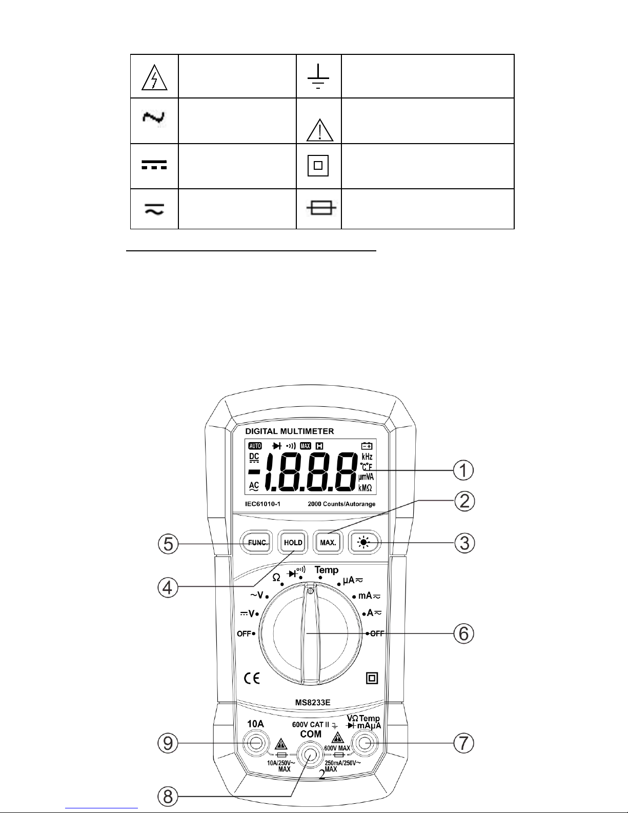
3-1. Meter illustration
2
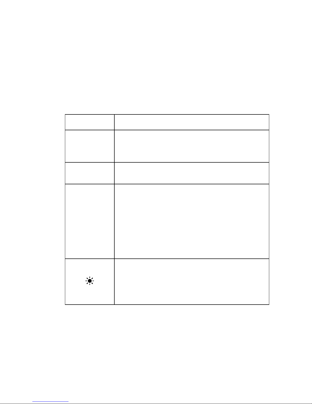
Fig. 1 Exterior view
1. LCD display 2. “MAX” button 3. “BACK LIGHT” button
4. ‘HOLD” button 5. “FUNC” button 6. Rotary Switch (Knob)
7. “V/Ω/HZ/uA/mA” input terminal 8. “COM” input terminal
9. “10A” input terminal
3-2. Functional button
Button
Function
FUNC
“FUNC” key is the function select key that acts with
trigger. Use the key as switch of DC/AC current,
Diode/Continuity.
HOLD
Press “HOLD” to enter and exit the hold mode in any
mode. That act with trigger.
MAX
This button is act with trigger. Press this button once, the
maximum value is holding (will display ‘MAX’ symbol
in the LCD).
After pressing the button, A/D will keep working, and
the display value are always updated and kept the
maximum value.
NOTE: The actual gained value is not the peak value.
This button is used to control Backlight. This button is
act with trigger. When press and hold the button over 2
sec, will enable Backlight.
Press the button again , the backlight will turn off.
3-3. Display indicators
3
 Loading...