

CREE LIGHTING THE EDGE ARE-EDG-DA, THE EDGE ARE-EDG-DL, THE EDGE ARE-EDR-DA, THE EDGE ARE-EDR-DL Installation Instructions Manual

THE EDGE®
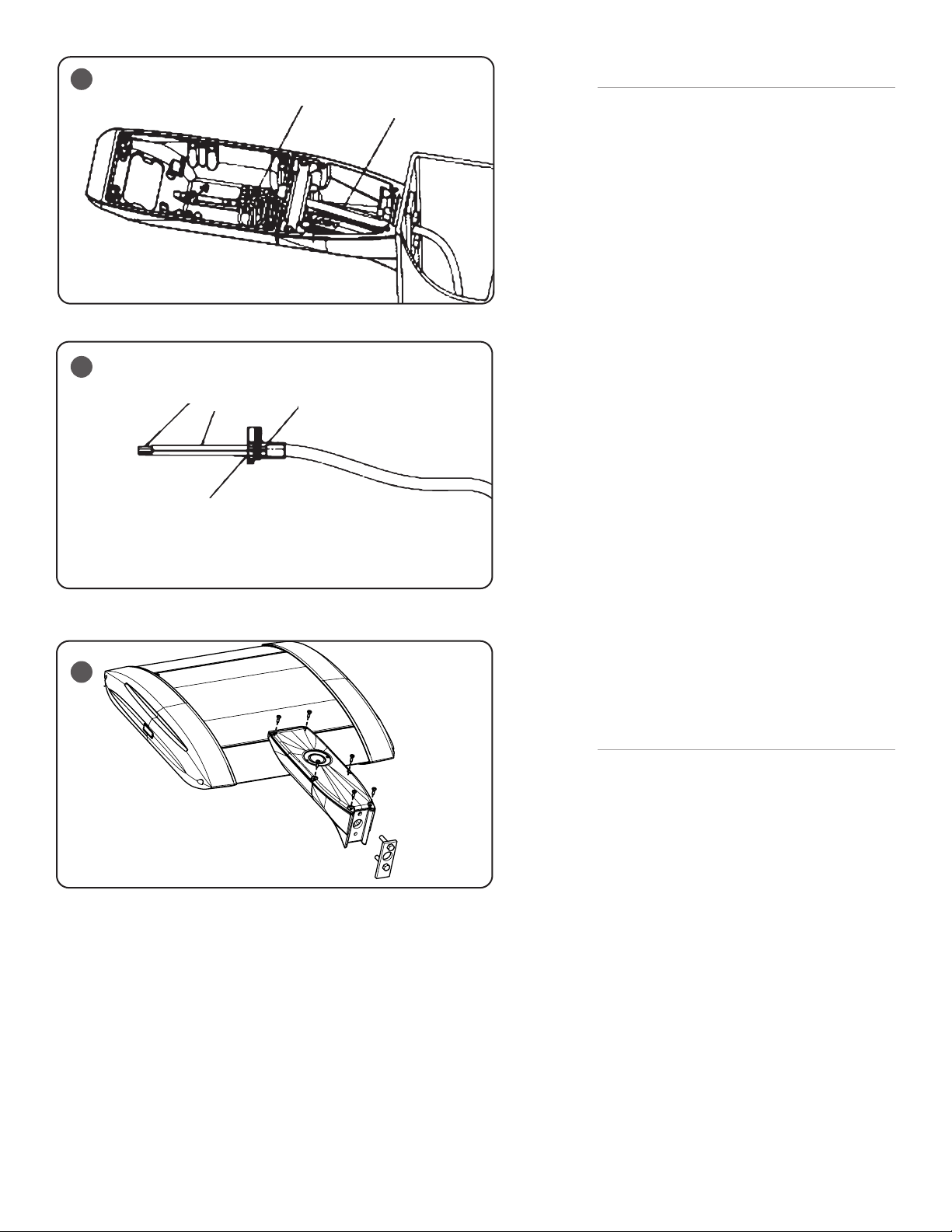
Fixture Arm
Mounting Clip
Universal Mount Arm
5/16-18
SS Nut
Foam Gasket
Mounting Plate
5/16-18 SS Bolt
Threaded Thru Plate
5/16-18 SS Bolt
5/16 Lock Washer
Thru Hole
Threaded Hole
5/16 Lock Washer
LED AREA DIRECT MOUNT
Includes: ARE-EDG-DA, ARE-EDG-DL, ARE-EDR-DA and ARE-EDR-DL
When using electrical equipment, basic safety precautions should always be followed
IMPORTANT SAFEGUARDS
including the following:
INSTALLATION INSTRUCTIONS
READ AND FOLLOW ALL SAFETY
INSTRUCTIONS
1. DANGER- Risk of shock- Disconnect power before installation.
DANGER – Risque de choc – Couper l’alimentation avant l’installation.
2. This luminaire must be installed in accordance with the NEC or your local electrical
code. If you are not familiar with these codes and requirements, consult a qualied
electrician.
Ce produit doit être installé conformément à NEC ou votre code électrique local.
Si vous n’êtes pas familier avec ces codes et ces exigences, veuillez contacter un
électricien qualié.
3. When handling, hold xture on sides to prevent damage to the top screen or LED’s
4. Take care to keep the LED lenses clean during installation.
SAVE THESE INSTRUCTIONS FOR FUTURE
REFERENCE
• Prior to installation, store luminaire in a dry location protected from rain, dust, and outdoor environment. If equipped with a photocell receptacle,
remove the protective cover only if immediately replacing with a suitable photocell, shorting cap, or other compatible device. The protective socket
cover is not intended to remain in place after installation. Do NOT leave receptacle open to environmental elements. Luminaires with a topmounted photocell receptacle should not be installed in an up-light position or at a tilt greater than 45 degrees from the down-light position.
TO INSTALL:
1
Fixture Arm
2
MOUNTING
STEP 1:
Use dimensions on template shown in Figure 2 for drilling if pole is not
pre-drilled. (Template not to scale.)
STEP 2:
Insert Backing Plate with pre-assembled bolt through the top mounting
hole. See Figure 1.
STEP 3:
Place gasket over bolt extending from pole. See Figure 1.
1 of 3
STEP 4:
Place the top hole of the Universal mounting arm over the top bolt from
the pole and secure with lock washer and 5/16” hex nut.
STEP 5:
Install remaining bolt with lock-washer thru the bottom hole and thread
into the Universal mounting arm. See Figure 1.
STEP 6:
Torque 5/16” hex nut and bolt to 132 in. lbs. (15 N•m).
Install fixture by sliding the fixture arm into the slot in the Universal
mounting arm. See Figure 1.
CI316X01R4_B
3
4
5
Strip Length 3/8”
Puncture Grommet Face w/
Stripped Wire
Strip Outer
Sheathing 3”
Terminal Block
Seal Against Stop in
Grommet
3 Conductor Cord
ELECTRICAL CONNECTIONS AND FINAL
ASSEMBLY
STEP 1:
Route supply wire from the pole into the Universal
Mounting arm. See Figure 3. The supply wire
should be long enough to extend at least 3” into
the fixture arm.
STEP 2:
Strip 3/8” of insulation from supply wires and insert
one wire into each of the three holes in the grommet.
Push the supply wires thru the plug so that they
puncture and go thru the grommet. Pull the wires so
that 3” of wire extend from the grommet. See Figure
4.
STEP 3:
Install the grommet with wires into the wire channel
between the Universal Mounting arm and the fixture
arm. See Figure 3.
Note: The grommet should be installed with the
flange side flush to the rear wall of the fixture arm.
STEP 4:
Install the mounting clip with the two screws
provided. See Figure 1.
STEP 5:
Insert supply wires into the appropriate terminal
connection and make electrical connections per
“ELECTRICAL CONNECTION” section.
IMPORTANT: Damage to fixture will result when
improper voltage is applied. Verify fixture is suitable
for supply voltage by checking electrical label on
fixture.
STEP 6:
Connect the ground lead from the arm cover into the
appropriate terminal connection.
STEP 7:
Install arm cover over both the Universal Mounting
Arm and the fixture arm using provided screws. See
Figure 5.
2 of 3
NEMA RECEPTACLE (OPTIONAL)
STEP 1:
Remove protective cap.
STEP 2:
Loosen two flat head screws holding NEMA receptacle
to housing a few turns.
STEP 3:
Locate the N symbol on receptacle, representing
north.
STEP 4:
Rotate N approximately north, some photo controls
operate best somewhere between NW and NE.
STEP 5:
Once orientation of receptacle is complete, tighten
screws from Step 1.
STEP 6:
Install photo control (supplied by customer).
CI316X01R4_B

ELECTRICAL CONNECTIONS-
PHASE to NEUTRAL WIRING – 120/277V
a. Push down on terminal marked for ground and insert supply ground
conductor.
b. Push down on terminal marked for N (Neutral) and insert supply
Neutral conductor.
c. Push down on terminal marked for L1 (Neutral) and insert supply
Hot conductor.
ELECTRICAL CONNECTIONSPHASE to PHASE WIRING – 208/240/480V
a. Push down on terminal marked for ground and insert supply
ground conductor.
b. Push down on terminal marked for N (Neutral) and insert supply
L2 (Hot) conductor.
c. Push down on terminal marked for L1 (Line) and insert supply L1
(Hot) conductor.
LINE L1
LINE-BLACK
LED FIXTURE
208, 240, 480V
SUPPLY WIRING
GREEN
LINE L2
GROUND-GREEN
NEUTRAL-WHITE
© 2019 Cree Lighting, A company of IDEAL INDUSTRIES. All rights reserved. For informational purposes only. Content is
subject to change. See www.creelighting.com/warranty for warranty and specifications. Cree® and the Cree logo are registered
trademarks of Cree, Inc. THE EDGE® is a registered trademark of Cree Lighting, A company of IDEAL INDUSTRIES. NEMA® is a
registered trademark of the National Electrical Manufacturers Association.
3 of 3
www.creelighting.com
CI316X01R4_B

THE EDGE®
Brazo de luminaria
Clip de montaje
Brazo de montaje universal
Tuerca de
5/16-18,
acero
inoxidable
Junta de espuma
Placa de montaje
Placa roscada para
tornillo de 5/16-18,
acero inoxidable
Tornillo de 5/16-18,
acero inoxidable
Arandela de seguridad de 5/16
Oricio pasante
Oricio roscado
Arandela de seguridad de 5/16
MONTAJE DIRECTO DE LA SUPERFICIE LED
Incluye: ARE-EDG-DA, ARE-EDG-DL, ARE-EDR-DA y ARE-EDR-DL
Al usar equipos eléctricos, siempre se deben seguir medidas de seguridad básicas,
MEDIDAS DE SEGURIDAD IMPORTANTES
incluidas las siguientes:
LEA Y SIGA TODAS LAS INSTRUCCIONES DE SEGURIDAD
1. PELIGRO: Riesgo de descarga eléctrica. Desconecte la alimentación eléctrica antes
de la instalación.
DANGER- Risk of shock- Disconnect power before installation.
2. Esta luminaria debe instalarse de acuerdo con el Código Eléctrico Nacional (NEC,
por sus siglas en inglés) o su código eléctrico local. Si no está familiarizado con estos
códigos y normas, consulte a un electricista califi cado.
This luminaire must be installed in accordance with the NEC or your local electrical code.
If you are not familiar with these codes and requirements, consult a qualifi ed electrician.
3. Durante la manipulación, sujete la luminaria por los costados para evitar que se
produzcan daños en la pantalla superior o en los LED.
4. Tenga cuidado de mantener limpios los lentes LED durante la instalación.
CONSERVE ESTAS INSTRUCCIONES PARA CONSULTAS POSTERIORES
• Antes de la instalación, guarde la luminaria en una ubicación seca protegida de la lluvia,
el polvo y el entorno exterior. Si está equipada con un receptáculo de fotocelda, retire
la cubierta protectora solo si se reemplaza de inmediato con una fotocelda, una tapa
supresora u otro dispositivo compatible. El protector del enchufe no está diseñado para
permanecer colocado luego de la instalación. NO deje el receptáculo expuesto a los
elementos ambientales. Las luminarias con un receptáculo de fotocelda montado en
la parte superior no deben instalarse en una posición con la luz hacia arriba o con una
inclinación mayor a 45° cuando la luz se encuentra hacia abajo.
PARA INSTALAR:
INSTRUCCIONES DE INSTALACIÓN
1
MONTAJE
PASO 1:
Utilice las dimensiones del esquema que se muestran en la Figura 2
para realizar la perforación si el poste no está perforado previamente.
(Elesquema no está a escala).
PASO 2:
Inserte la placa de apoyo con un tornillo preensamblado en el orificio
superior de montaje. Vea la Figura 1.
PASO 3:
Coloque la junta sobre el tornillo que se extiende del poste. Vea la Figura 1.
1 de 3
2
Se requieren 2
orifi cios
de 0.344”
(9 mm)
de diámetro
1”
(25 mm)
Orifi cio
de 0.500”
(13 mm)
de diámetro
NO ESTÁ A ESCALA
PASO 4:
Coloque el orificio superior del brazo de montaje universal sobre el tornillo
superior del poste y asegúrelo con una arandela de seguridad yuna tuerca
hexagonal de 5/16”.
PASO 5:
Coloque el tornillo restante en el orificio inferior con una arandela de
seguridad y atorníllelo en el brazo de montaje universal. Vea la Figura 1.
PASO 6:
Apriete el tornillo y la tuerca hexagonal de 5/16” a un valor de 132in.lb. (15 Nm).
Deslice el brazo de la luminaria hacia la ranura del brazo de montaje
universal para instalar la luminaria. Vea la Figura 1.
2.000”
(51 mm)
2.000”
(51 mm)
CI316X01R4_B

3
4
Largo del recorte: 3/8”
5
Pele el
revestimiento
exterior 3”
Perfore el pasacables con
el cable pelado
Bloque de terminales
Séllelo contra la parte
superior del pasacables
Cable conductor 3
CONEXIONES ELÉCTRICAS Y ENSAMBLAJE FINAL
PASO 1:
Pase el cable de alimentación del poste por el brazo
de montaje universal. Vea la
alimentación debería ser lo suficientemente largo
como para extenderse por lo menos 3” dentro del
brazo de la luminaria.
Figura3. El cable de
PASO 2:
Pele 3/8” del aislamiento de los cables de alimentación
e inserte un cable en cada uno de los tres orificios
del pasacables. Empuje los cables de alimentación
contra el tapón para que lo perforen y atraviesen el
pasacables. Jale los alambres hasta que haya 3” de
cable fuera del pasacables. Vea la
Figura4.
PASO 3:
Instale el pasacables con los cables en el canal para
cables entre el brazo de montaje universal y el brazo
de la luminaria. Vea la
Nota: El pasacables se debe instalar de manera que
la brida lateral esté alineada con la pared trasera del
brazo de la luminaria.
Figura 3.
PASO 4:
Instale el clip de montaje con los dos tornillos
provistos. Vea la
Figura 1.
PASO 5:
Inserte los cables de alimentación en la conexión
del terminal apropiado y realice las conexiones
eléctricas de acuerdo con la sección “CONEXIONES
ELÉCTRICAS”.
IMPORTANTE: La aplicación del voltaje erróneo
provocará daños a la luminaria. Verifique que
la luminaria sea adecuada para el voltaje de la
alimentación eléctrica existente según indica la
etiqueta en la luminaria.
PASO 6:
Conecte el conductor a tierra de la cubierta del brazo
a la conexión del terminal apropiado.
PASO 7:
Instale la cubierta del brazo sobre el brazo de
montaje universal y el brazo de la luminaria con los
tornillos provistos. Vea la
Figura 5.
2 de 3
RECEPTÁCULO NEMA (OPCIONAL)
PASO 1:
Retire la tapa protectora.
PASO 2:
Afloje los dos tornillos de cabeza plana que sujetan el
receptáculo NEMA a la carcasa con unas cuantas vueltas.
PASO 3:
Localice el símbolo N en el receptáculo, que representa
el norte.
PASO 4:
Gire la N aproximadamente al norte, algunos
controles fotoeléctricos funcionan mejor cuando
apuntan en dirección NO y NE.
PASO 5:
Una vez terminada la orientación del receptáculo,
apriete los tornillos del
Paso 1.
PASO 6:
Instale el control fotoeléctrico (suministrado por
el cliente).
CI316X01R4_B

CONEXIONES ELÉCTRICAS -
CABLEADO de FASE a NEUTRO – 120/277V
a. Empuje hacia abajo el terminal marcado para conexión a tierra
einserte el conductor de conexión a tierra de la alimentación.
b. Empuje hacia abajo el terminal marcado para N (neutro) e inserte
el conductor Neutro de la alimentación.
c. Empuje hacia abajo el terminal marcado para L1 (línea) e inserte el
conductor energizado de la alimentación.
LÍNEA
TIERRA
LÍNEA (NEGRO)
TIERRA
LUMINARIA LED
CONEXIONES ELÉCTRICAS CABLEADO de FASE a FASE – 208/240/480V
a. Empuje hacia abajo el terminal marcado para conexión a tierra
einserte el conductor de conexión a tierra de la alimentación.
b. Empuje hacia abajo el terminal marcado para N (neutro) e inserte
el conductor L2 (energizado) de la alimentación.
c. Empuje hacia abajo el terminal marcado para L1 (línea) e inserte
el conductor L1 (energizado) de la alimentación.
NEUTRO
ALIMENTACIÓN
LÍNEA L1
208, 240, 480 V
CABLEADO DE ALIMENTACIÓN
VERDE
LÍNEA L2
COMÚN (BLANCO)
LUMINARIA LED
LÍNEA NEGRO
TIERRA – VERDE
NEUTRO – BLANCO
© 2019 Cree Lighting, una compañía de IDEAL INDUSTRIES. Todos los derechos reservados. Sólo para fines informativos. El
contenido está sujeta a cambios. Consulte www.creelighting.com/warranty para la garantía y las especificaciones. Cree® y el
logotipo de Cree son marca registrada de Cree, Inc. XSP1™ y XSP2™ son marcas comerciales de IDEAL INDUSTRIES. NEMA® es
una marca registrada de la Asociación Nacional de Fabricantes Eléctricos.
3 de 3
www.creelighting.com
CI316X01R4_B
 Loading...