

CREE LIGHTING THE EDGE ARE-EDG-DA, THE EDGE ARE-EDG-DL, THE EDGE ARE-EDR-DA, THE EDGE ARE-EDR-DL Installation Instructions Manual

THE EDGE®
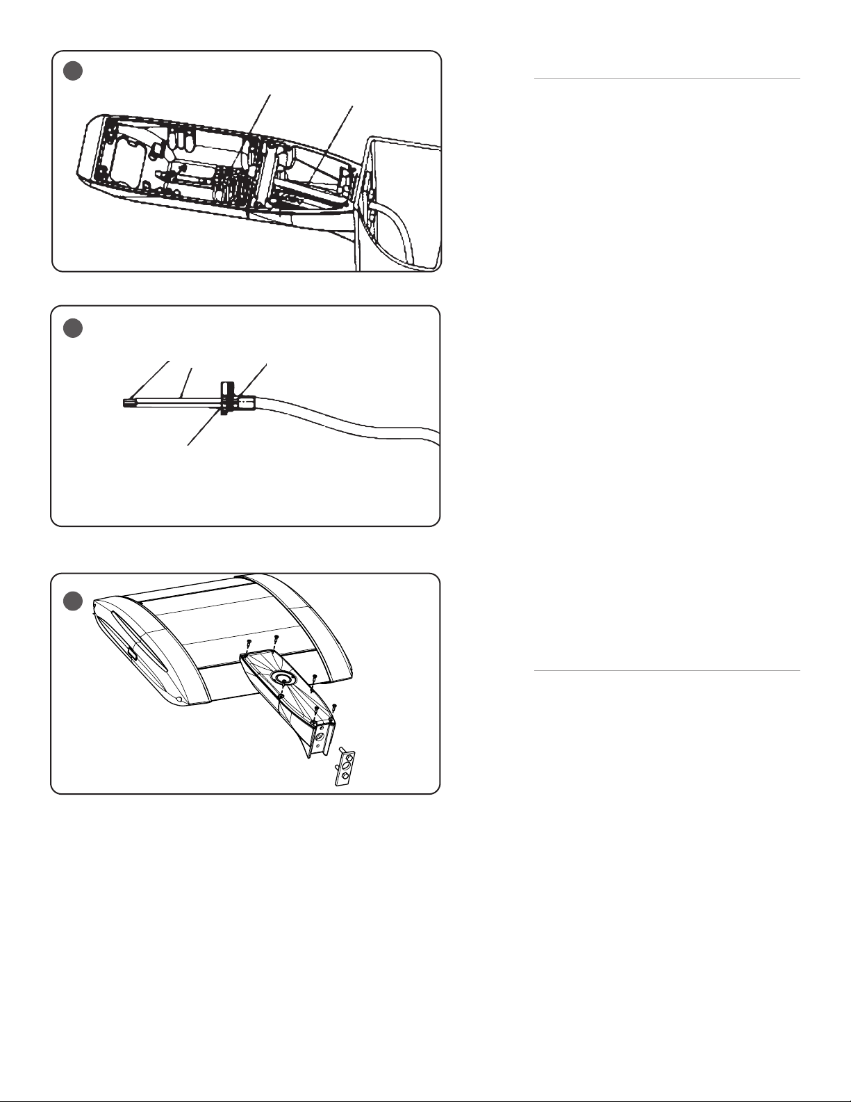
Fixture Arm
Mounting Clip
Universal Mount Arm
5/16-18
SS Nut
Foam Gasket
Mounting Plate
5/16-18 SS Bolt
Threaded Thru Plate
5/16-18 SS Bolt
5/16 Lock Washer
Thru Hole
Threaded Hole
5/16 Lock Washer
LED AREA DIRECT MOUNT
Includes: ARE-EDG-DA, ARE-EDG-DL, ARE-EDR-DA and ARE-EDR-DL
When using electrical equipment, basic safety precautions should always be followed
IMPORTANT SAFEGUARDS
including the following:
INSTALLATION INSTRUCTIONS
READ AND FOLLOW ALL SAFETY
INSTRUCTIONS
1. DANGER- Risk of shock- Disconnect power before installation.
DANGER – Risque de choc – Couper l’alimentation avant l’installation.
2. This luminaire must be installed in accordance with the NEC or your local electrical
code. If you are not familiar with these codes and requirements, consult a qualied
electrician.
Ce produit doit être installé conformément à NEC ou votre code électrique local.
Si vous n’êtes pas familier avec ces codes et ces exigences, veuillez contacter un
électricien qualié.
3. When handling, hold xture on sides to prevent damage to the top screen or LED’s
4. Take care to keep the LED lenses clean during installation.
SAVE THESE INSTRUCTIONS FOR FUTURE
REFERENCE
• Prior to installation, store luminaire in a dry location protected from rain, dust, and outdoor environment. If equipped with a photocell receptacle,
remove the protective cover only if immediately replacing with a suitable photocell, shorting cap, or other compatible device. The protective socket
cover is not intended to remain in place after installation. Do NOT leave receptacle open to environmental elements. Luminaires with a topmounted photocell receptacle should not be installed in an up-light position or at a tilt greater than 45 degrees from the down-light position.
TO INSTALL:
1
Fixture Arm
2
MOUNTING
STEP 1:
Use dimensions on template shown in Figure 2 for drilling if pole is not
pre-drilled. (Template not to scale.)
STEP 2:
Insert Backing Plate with pre-assembled bolt through the top mounting
hole. See Figure 1.
STEP 3:
Place gasket over bolt extending from pole. See Figure 1.
1 of 3
STEP 4:
Place the top hole of the Universal mounting arm over the top bolt from
the pole and secure with lock washer and 5/16” hex nut.
STEP 5:
Install remaining bolt with lock-washer thru the bottom hole and thread
into the Universal mounting arm. See Figure 1.
STEP 6:
Torque 5/16” hex nut and bolt to 132 in. lbs. (15 N•m).
Install fixture by sliding the fixture arm into the slot in the Universal
mounting arm. See Figure 1.
CI316X01R4_B
3
4
5
Strip Length 3/8”
Puncture Grommet Face w/
Stripped Wire
Strip Outer
Sheathing 3”
Terminal Block
Seal Against Stop in
Grommet
3 Conductor Cord
ELECTRICAL CONNECTIONS AND FINAL
ASSEMBLY
STEP 1:
Route supply wire from the pole into the Universal
Mounting arm. See Figure 3. The supply wire
should be long enough to extend at least 3” into
the fixture arm.
STEP 2:
Strip 3/8” of insulation from supply wires and insert
one wire into each of the three holes in the grommet.
Push the supply wires thru the plug so that they
puncture and go thru the grommet. Pull the wires so
that 3” of wire extend from the grommet. See Figure
4.
STEP 3:
Install the grommet with wires into the wire channel
between the Universal Mounting arm and the fixture
arm. See Figure 3.
Note: The grommet should be installed with the
flange side flush to the rear wall of the fixture arm.
STEP 4:
Install the mounting clip with the two screws
provided. See Figure 1.
STEP 5:
Insert supply wires into the appropriate terminal
connection and make electrical connections per
“ELECTRICAL CONNECTION” section.
IMPORTANT: Damage to fixture will result when
improper voltage is applied. Verify fixture is suitable
for supply voltage by checking electrical label on
fixture.
STEP 6:
Connect the ground lead from the arm cover into the
appropriate terminal connection.
STEP 7:
Install arm cover over both the Universal Mounting
Arm and the fixture arm using provided screws. See
Figure 5.
2 of 3
NEMA RECEPTACLE (OPTIONAL)
STEP 1:
Remove protective cap.
STEP 2:
Loosen two flat head screws holding NEMA receptacle
to housing a few turns.
STEP 3:
Locate the N symbol on receptacle, representing
north.
STEP 4:
Rotate N approximately north, some photo controls
operate best somewhere between NW and NE.
STEP 5:
Once orientation of receptacle is complete, tighten
screws from Step 1.
STEP 6:
Install photo control (supplied by customer).
CI316X01R4_B
 Loading...