

CREE LIGHTING Stylus Series Installation Instructions Manual
IMPORTANT SAFEGUARDS
When using electrical equipment, basic safety precautions should always be followed
including the following:
READ AND FOLLOW ALL
SAFETY INSTRUCTIONS
1. DANGER- Risk of shock- Disconnect power before installation.
DANGER – Risque de choc – Couper l’alimentation avant l’installation.
2. This luminaire must be installed in accordance with the NEC or your local
electrical code. If you are not familiar with these codes and requirements,
consult a qualied electrician.
Ce produit doit être installé conformément à NEC ou votre code électrique
local. Si vous n’êtes pas familier avec ces codes et ces exigences, veuillez
contacter un électricien qualié.
3. SUITABLE FOR CONTINUOUS ROW MOUNTING.
PEUT ÊTRE MONTÉ EN RANGÉE CONTINUE.
4. Make sure the equipment is properly grounded.
5. Always de-energize the circuit and/or equipment before connecting to,
disconnecting from or servicing the equipment
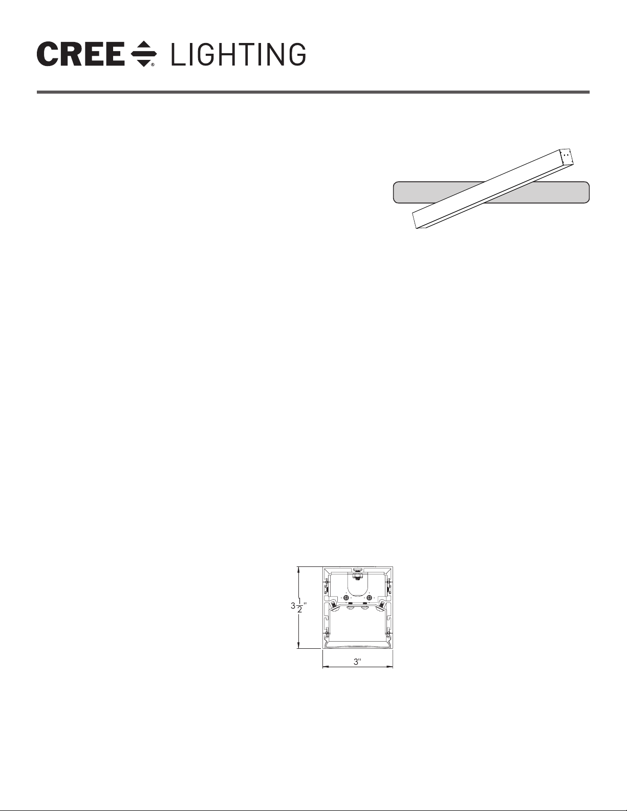
Stylus Series
LED Ambient Luminaire
Ceiling/Surface Mount
INSTALLATION INSTRUCTIONS
INSTRUCTIONS D’INSTALLATION
Installation Instructions are divided into
3 sections:
1. Surface Mounting - Individual Luminaire
2. Surface Mounting - Continuous Row
SAVE THESE INSTRUCTIONS
3. Electrical Connections
FOR FUTURE REFERENCE
NOTES:
• CAUTION - It is the installers responsibility to ensure that ceiling is structurally capable of supporting the weight of luminaire/luminaire row.
• Endcap kits and joining hardware are packaged separately for continuous rows.
• To Prevent Luminaire Row From Over-Current: By adding the input current of each luminaire section marked on the luminaire, the total current per
power feed must not exceed the maximum line wire amperage rating in the luminaire and the power feed cord/wire amperage rating whichever is
least.
1 of 6
ST3-SF
LPN00644X0007A0_A
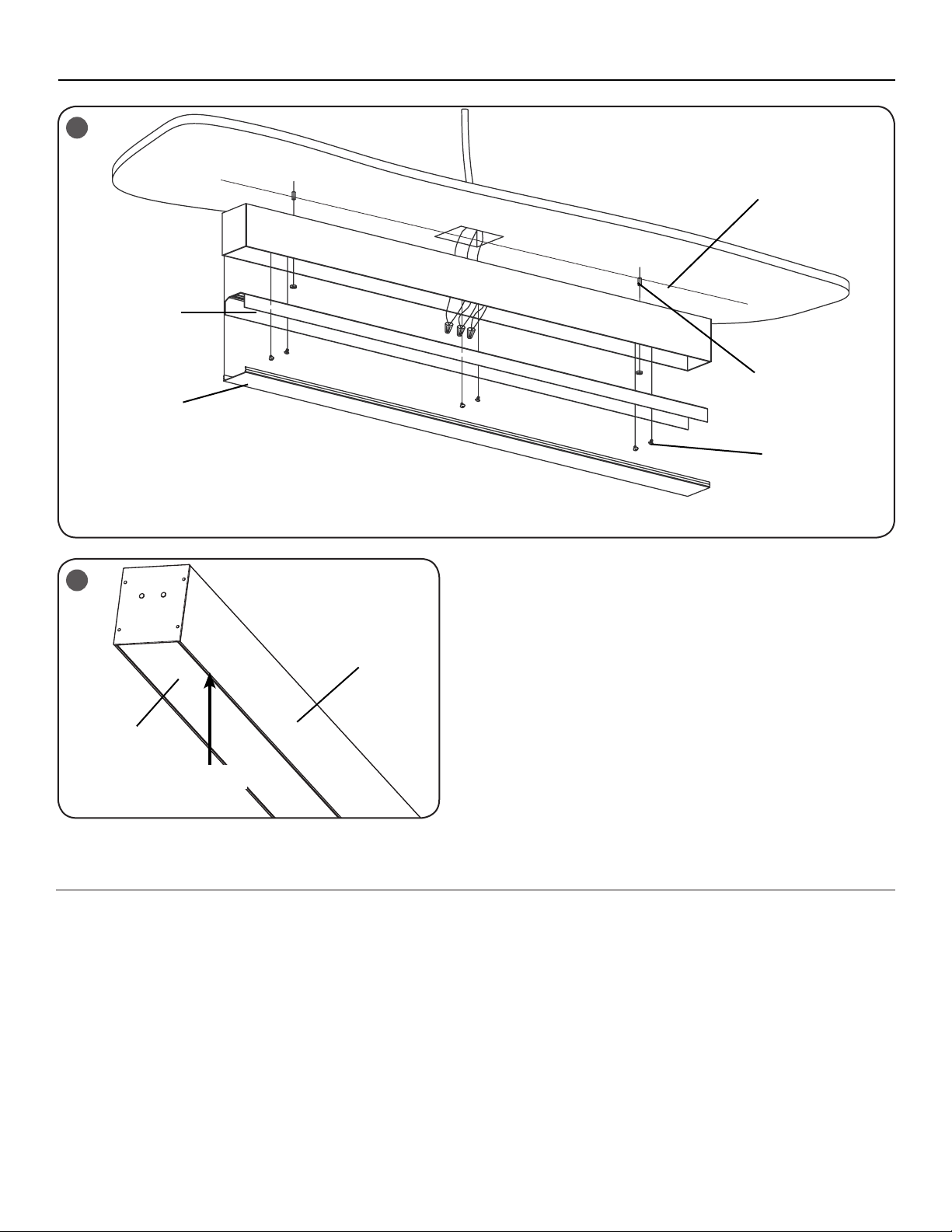
TO INSTALL:
1
LED Reflector
Tray
Lens
Chalk Line
Fasteners
(Supplied By Others)
Fasteners
2
Lens
Slide Plastic Card
or Putty Knife Here
SECTION 1:
SURFACE MOUNTINGINDIVIDUAL LUMINAIRE
CAUTION: Luminaires should be secured
to structure above to support weight of
luminaire.
STEP 1:
Remove lens and LED/reflector tray and set
aside in order of run placement for reinstalling
later. To remove lens, carefully slide a plastic
card or putty knife between the lens and
extrusion towards the end of the luminaire.
Using the plastic card or putty knife, push the
lens inward until the lens comes free. See
Figure 1 and 2.
STEP 2:
After removing the lens, remove the Phillips
head reflector screws, remove the LED
Reflector Tray, and disconnect the LED
Extrusion
harness. Set lens and LED Reflector tray
aside. See Figure 1.
STEP 3:
Use the luminaire as a template to locate the
mounting holes by centering luminaire over
recessed switch box. Keep the switch box square
to and on center lengthwise, mark each mounting
anchors hole location, See Figure 2. Ensure that
all mounting points are on the same center line
as the switch box installed. Drill appropriate holes
for mounting surface and fasteners to be used.
Securely attach housing to ceiling: See Figure 1.
NOTE: Pre-drilled diameter 5/8" mounting
anchor holes are located 2.13" from the end
of each luminaire. See Figure 3 on the next
page.
STEP 4:
Using the 1.5” diameter hole located in the
center of the luminaire, route the electrical
leads out into customer supplied junction box
and make electrical connections per Section 3
“Electrical Connections”.
STEP 5:
Reconnect LED harness. Replace LED trays
and lens that was removed in Step 1 & 2
above, ensure that no wires are pinched.
2 of 6
LPN00644X0007A0_A
 Loading...