

CREE LIGHTING SMK-CR14, SMK Series, SMK-CR22, SMK-CR24 Installation Instructions Manual
SMK
Specification Troffers
Includes: SMK-CR14, SMK-CR22 and SMK-CR24
IMPORTANT SAFEGUARDS
When using electrical equipment, basic safety precautions should always be followed
including the following:
READ AND FOLLOW ALL SAFETY
INSTRUCTIONS
1. DANGER- Risk of shock- Disconnect power before installation.
DANGER – Risque de choc – Couper l’alimentation avant l’installation.
2. This luminaire must be installed in accordance with the NEC or your local electrical code.
If you are not familiar with these codes and requirements, consult a qualied electrician.
Ce produit doit être installé conformément à NEC ou votre code électrique local. Si vous
n’êtes pas familier avec ces codes et ces exigences, veuillez contacter un électricien
qualié.
3. Do not install insulation within 3 inches (76 mm) of any part of the luminaire.
Ne pas mettre l’isolant a moins de 76 mm (3 po) de toute partie du luminaire.
4. Access above ceiling required.
Acces requis au-dessus du plafond.
5. Suitable for Damp Locations.
Convient aux emplacements humides.
6. Suitable for suspended ceilings.
Convient aux plafonds suspendus.
SAVE THESE INSTRUCTIONS FOR FUTURE
REFERENCE
• The Surface Mount Kit is designed for use with CR Series Troffers for surface or
suspended mounting.
• The following are not provided: conduit, cable, ttings, terminal blocks and wire connectors.
TO INSTALL:
INSTALLATION INSTRUCTIONS
INSTRUCTIONS D’INSTALLATION
SMK-CR14
SMK-CR22
SMK-CR24
1
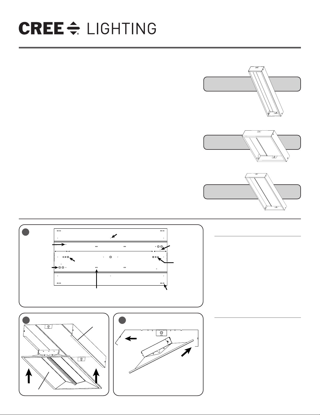
Cable Mount
Knockouts (4)
ø 0.25"
Electrical
Knockouts (7)
ø 0.88"
2 3
Troffer
1 of 2
6" 6"36.25"
Pendant Mount
Knockouts (2)
ø 0.68"
Wire-tie loops
for internal wire
management (4)
0.82" W x 0.25" H
Inside Edge
of Housing
Mounting
Holes (10)
ø 0.13"
Grounding
Studs (2)
Stand-O
Loop (2)
1.32" W x 0.50" H
S-Hook
Knockouts (4)
0.60" W x 0.30" H
INSTALL BASE HOUSING ON TO
SURFACE OR SUSPEND FROM CHAIN:
STEP 1:
For all mounting features and wiring access
points see Figure 1.
NOTE: Distance between the two Pendant Mount
Knockouts for SMK-CR24 and SMK-CR14 is
36.25", and 6" from each edge. The distance
between the two Pendant Mount Knockouts for
SMK-CR22 is 15", and 5" from each edge.
STEP 2:
Attach ground wire lead to grounding stud of
your choice using included ground nut.
INSTALL CR SERIES TROFFER INTO
BASE HOUSING:
STEP 1:
Place one edge of CR Series Troffer on inside
edge of housing. See Figure 2.
STEP 2:
Pull housing side wall outward. Rotate troffer
into housing. See Figure 3.
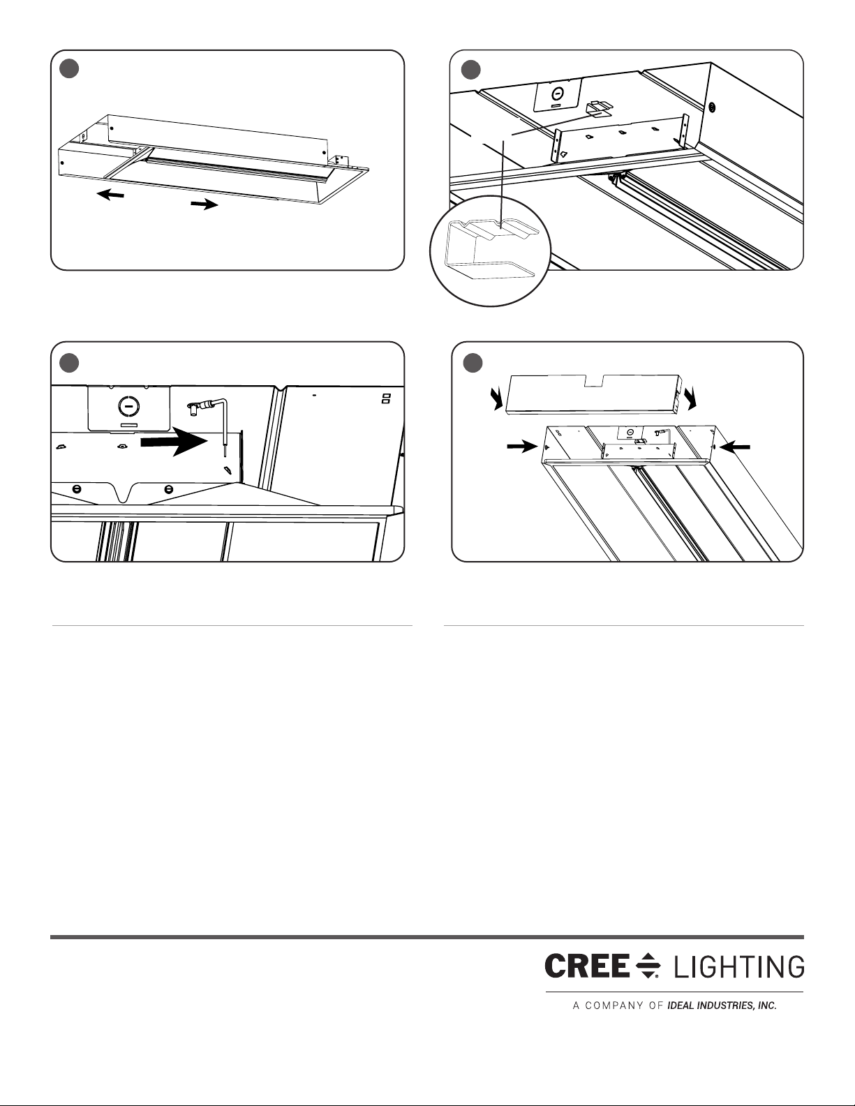
STEP 3:
Route all AC wires through knockouts and
attach to CR Series Troffer leads as indicated
in the installation instructions included with
the CR Series Troffers. Dress wires using
zip-ties (not provided) through loops where
indicated above.
LPN000129_B
4
5
Stand-Off
Bracket
76
INSTALL STANDOFF BRACKETS AND GROUND WIRE:
STEP 1:
Slide the CR Series Troffer to either end of the housing to expose the standoff loop. See Figure 4.
INSTALL END CAPS:
STEP 1:
Install an End Cap on each end to complete the enclosure and secure
with (2) sheet metal screws each. See Figure 7.
STEP 2:
Install stand-off brackets by sliding the tab with the detent bumps into the
receiving loop. See Figure 5.
STEP 3:
Install ground wire with the (8-32) star nut (provided). See Figure 6.
© 2019 Cree Lighting, A company of IDEAL INDUSTRIES. All rights reserved. For informational purposes only. Content
is subject to change. See www.creelighting.com/warranty for warranty and specifications. Cree® and the Cree logo are
registered trademarks of Cree, Inc. CR14™, CR22™ and CR24™ are trademarks of Cree Lighting, A company of IDEAL
INDUSTRIES.
www.creelighting.com
2 of 2
LPN000129_B
 Loading...