

CREE LIGHTING SmartCast CSC-GW-CWC-W User Manual

SmartCast
CSC-GW-CWC-W
®
Wireless Gateway with WiFi
When using electrical equipment, basic safety precautions should always be followed
including the following:
READ AND FOLLOW ALL SAFETY
INSTRUCTIONS
IMPORTANT SAFEGUARDS
1. DANGER- Risk of shock- Disconnect power before installation.
DANGER – Risque de choc – Couper l’alimentation avant l’installation.
2. Must be installed in accordance with the NEC or your local electrical code. If you
are not familiar with these codes and requirements, consult a qualied electrician.
Ce produit doit être installé conformément à NEC ou votre code électrique local.
Si vous n’êtes pas familier avec ces codes et ces exigences, veuillez contacter
un électricien qualié.
3. Indoor use only and Suitable for Damp Locations.
Pour usage interieur seulement et convient aux emplacements humides.
4. This equipment shall be installed and operated with a minimum distance 20cm
between the radiator and your body.
L’équipement doit etre installe d’une facon qu’une distance minimum de 20cm soit
maintenue entre l’emetteur et toute partie du corps.
SAVE THESE INSTRUCTIONS FOR
FUTURE REFERENCE
• Suitable for use in other Environmental Air Space (Plenums)
in accordance with section 300.22,(C) of the National Electrical
Code, and Sections 2-128, 12-010(3) and 12-100 of the Canadian
Electrical Code, Part 1 CSA C22.1
Peut être utilisé dans de gaines transportant de l’air traité,
conformément à la section 300.22,(C) du National Electrical Eode
et aux articles 2-128, 12-010(3) ET 12-100 du Code Candian de
l’électricité Premiére partie, CSA C22.1.
• Plenum rated cables need to be used when the SWG is installed in
a plenum.
• SWG needs to connected to PoE networks without routing to outside
plant connections.
• When this product is supplied by the Listed Direct
Plug-In Power Unit Starwell Technology PSE-480050US it is
intended to be used in a 25C environment up to 2000m.
INSTALLATION INSTRUCTIONS
1
T-BAR MOUNTING
STEP 1:
Plug customer supplied Ethernet RJ45
cable into the RJ45 cable port located on the
backside of the device. See Figure 1.
NOTE: Plenum rated cables need to be used
when the SWG is installed in a plenum.
1 of 3
2
RJ45 Cable Port
Back of the SWG Unit
STEP 2:
Insert the T-Bar clip into the back of the SWG
unit using provided screw as shown in
Figure 2.
STEP 3:
NOTE: Before you attach the SWG device,
please save the details from the label on the
back of the device - SSID and password. You
will need these details to login and connect to
the device over Wi-Fi.
T-Bar Clip
T-Bar Clip
Arms
Screw
To attach the SWG device to the ceiling
T-bar, rotate the device counter clockwise 45
degrees and apply an upward force to engage
the T-bar clip. While maintaining the upward
force, rotate the device clockwise 45 degrees
to snap and lock the device to the T-bar.
STEP 4:
Connect the supplied Ethernet RJ45 cable to
the POE wall supply (POE Port) .
LPN00655X0001A0_C
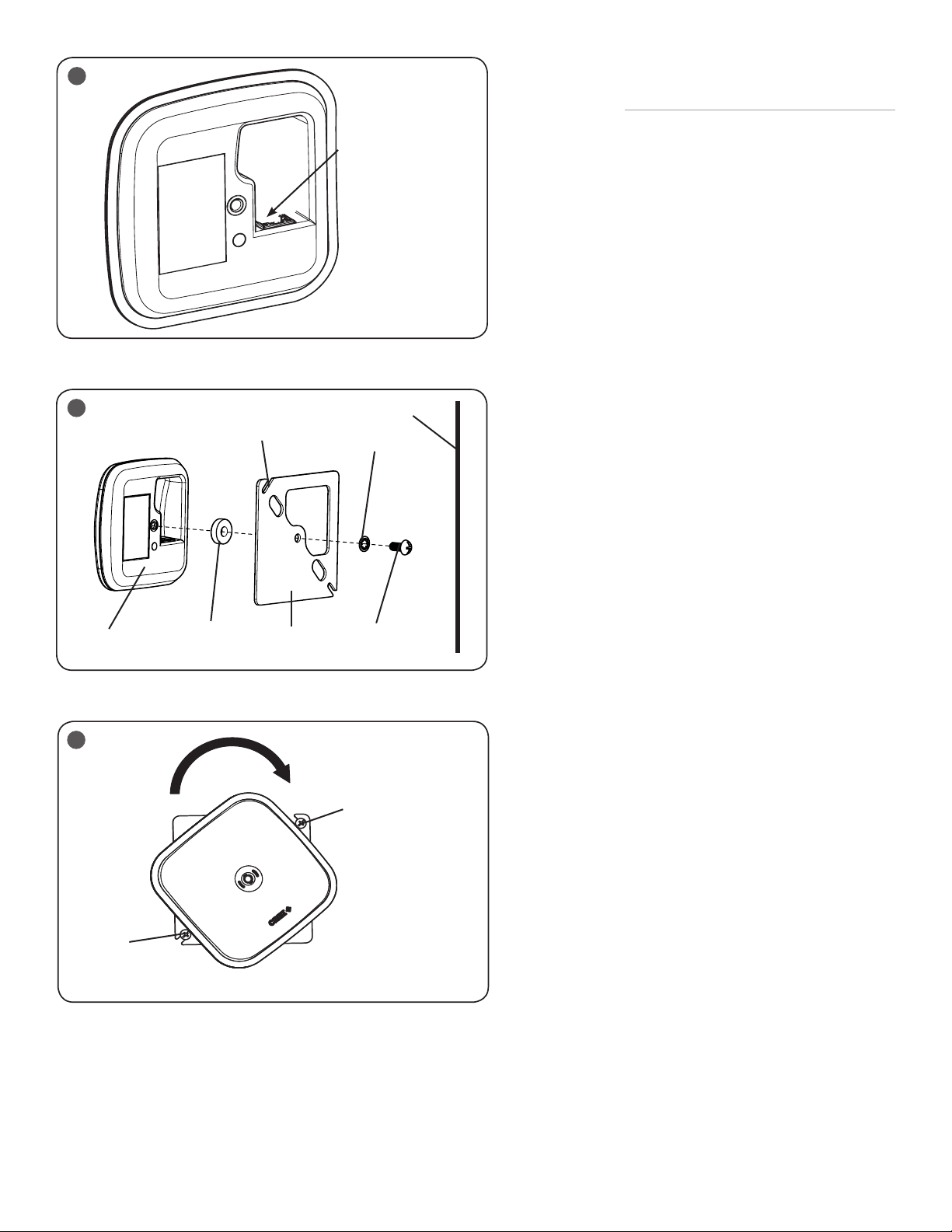
3
4
Back of the SWG
Unit
Spacer
Metal Plate
Slot
Metal Plate
RJ45 Cable Port
Mounting
Surface
Washer
Screw
SURFACE MOUNTING USING JUNCTION
BOX ADAPTER-
REQUIRES CSC-GW-JBOX-ADPTR
STEP 1:
Using provided screw, washer and spacer attach
the metal plate to the back of the SWG unit as
shown in Figure 4.
STEP 2:
Plug supplied Ethernet RJ45 cable into the RJ45
cable port located on the device. See Figure 3.
NOTE: Plenum rated cables need to be used
when the SWG is installed in a plenum.
STEP 3:
Insert provided (2) screws or drywall screws
into the slots on each end of the metal plate and
attach the unit to the desired surface or mount.
See Figure 5.
STEP 4:
Rotate the whole unit 45 degrees clockwise in
order to hide the screw holes. See Figure 5.
STEP 5:
Connect the supplied Ethernet RJ45 cable to the
PoE wall supply (PoE Port).
STEP 6:
Please make sure the device is powered and
operational. Please refer to the STATUS LED
INDICATOR TABLE in the Troubleshooting section
on page 3.
STEP 7:
Please proceed to configure the device using
SmartCast documentation available at
https://www.creelighting.com/touchscreen-help.
5
Screw in Metal
Plate Slot to
Attach to Surface
or Mount
2 of 3
Screw in
Metal Plate
Slot to Attach
to Surface or
Mount
LPN00655X0001A0_C
 Loading...