

CREE LIGHTING KBL Series, KBL WITH ML SENSOR, KBL WITH PML SENSOR, KBL Installation Instructions Manual
KBL Series
LED Luminaire
Universal Hook and Cord or Pendant Mount
IMPORTANT SAFEGUARDS
When using electrical equipment, basic safety precautions should
always be followed including the following:
READ AND FOLLOW ALL
SAFETY INSTRUCTIONS
1. DANGER- Risk of shock- Disconnect power before installation.
DANGER – Risque de choc – Couper l’alimentation avant
l’installation.
2. This luminaire must be installed in accordance with the NEC or
your local electrical code. If you are not familiar with these codes
and requirements, consult a qualied electrician.
Ce produit doit être installé conformément à NEC ou votre code
électrique local. Si vous n’êtes pas familier avec ces codes et ces
exigences, veuillez contacter un électricien qualié.
3. Suitable for damp location.
Convient aux emplacements humides.
4. Maximum ambient operating temperature: 9L, 12L, 18L (M) =
50°C and 24L (H), and 30L= 40°C.
Température ambiante maximale de fonctionnement:
9L, 12L, 18L (M) = 50°C et 24L (H), et 30L= 40°C.
5. MIN 90°C SUPPLY CONDUCTORS
LES FILS D’ALIMENTATION 90°C MIN.
6. Check to make sure that all input power connections have been
properly made and the module is grounded to avoid potential
electrical shock.
7. DO NOT lift luminaire by the power cord or any of the cables
connected to the LED heatsink and LED driver.
INSTALLATION INSTRUCTIONS
INSTRUCTIONS D’INSTALLATION
KBL
KBL WITH ML
SENSOR
SAVE THESE INSTRUCTIONS
FOR FUTURE REFERENCE
NOTES:
• Images used in this installation sheet are for illustration purpose,
there are different congurations of the luminaire.
• For each mounting application below, when mounting to surface
ensure that the mounting surface and customer supplied
hardware is capable of supporting the weight of the luminaire.
• The center of mounting is NOT the same as the center of
luminaire.
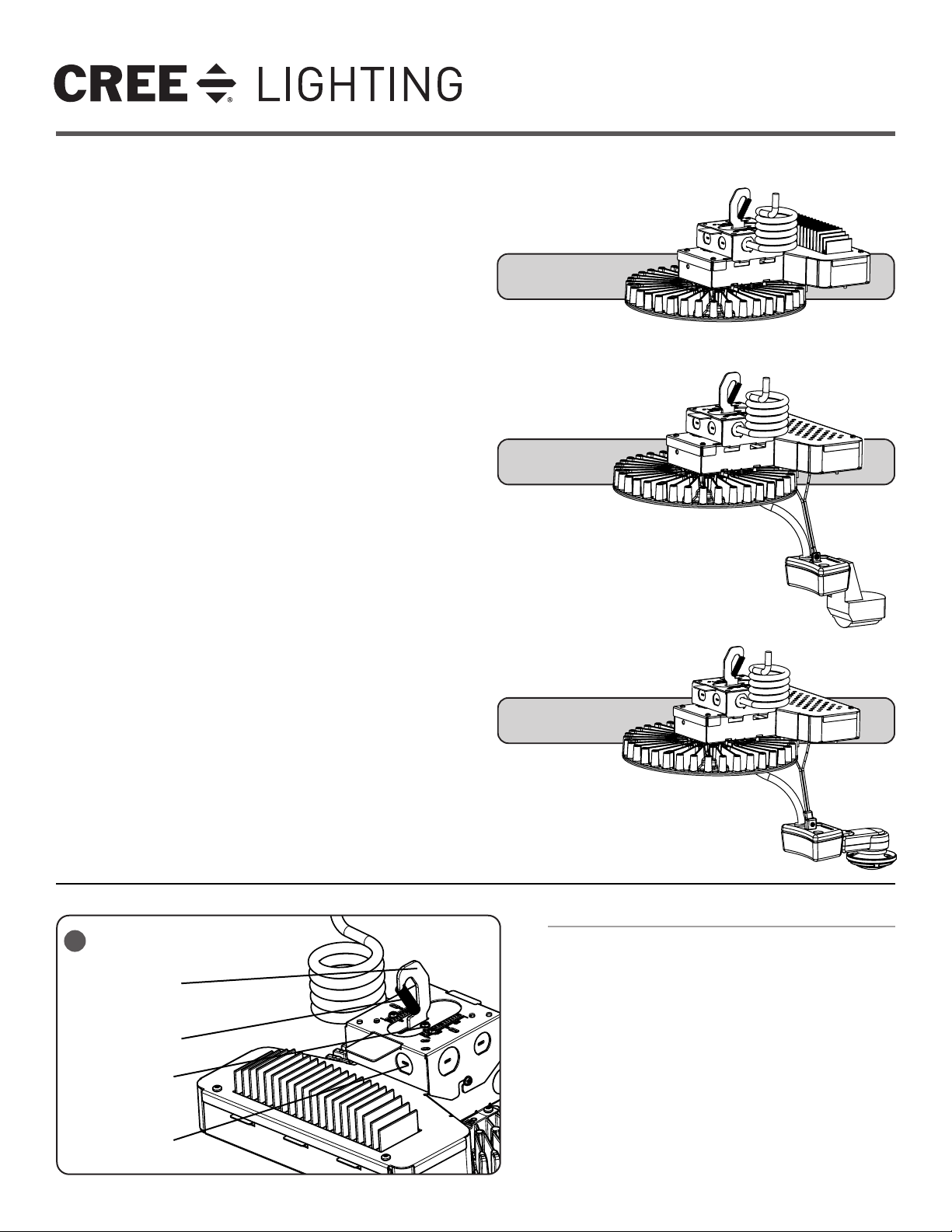
TO INSTALL:
1
Luminaire Hook
Retainer Spring
Hook Adjustment Screws
1/2” (13mm) IP, 0.875”
(22mm) O.D. Knockout
1 of 6
KBL WITH PML
SENSOR
HOOK AND CORD MOUNT
STEP 1:
Push down on retainer spring until top of spring is free of
luminaire hook. See Figure 1.
STEP 2:
Slide hook into securely mounted customer supplied eye
hanger and return retainer spring to original position.
NOTE: The luminaire should already be factory set for correct
balance. If necessary, the fixture may be balanced by loosening
the hook adjustment screws on the top of the housing and
sliding the hook as necessary for correct balance. Tighten hook
adjustment screws when finished. See Figure 1.
STEP 3:
Make wiring connections per the Electrical Connections
section. After electrical connections for luminaires with a
sensor go to pages 4-6 for installation of sensor.
LPN00513X0001A4_D
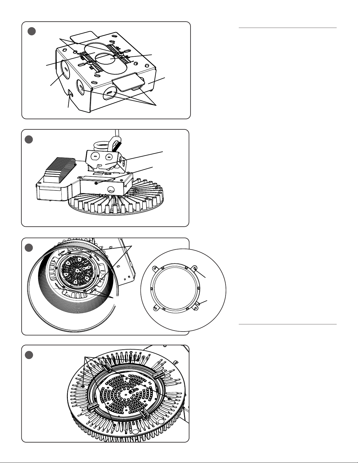
2
Adjustment Screws
Pendant Slider
Plate
3/4” (19mm) IP,
1.125” (29mm)
O.D. Knockouts
3
4
“L” Channel
(4) Keyhole
Slots
Pendant Mount Hole
3/4” (19mm) IP, 1.125”
(29mm) O.D.
Hinged Splice
Box
1/2” (13mm) IP,
0.875” (22mm)
O.D. Knockouts
Hinged J-box
Hinged J-box
Screw
Add 2 Screws For Aluminum
Reflectors
(4)
Luminaire
Mounting
Tabs
Locking
Feature
PENDANT MOUNT
STEP 1:
Remove hinged splice box from top of housing
by loosening screw and sliding box to the right
and up from “L” channel. Unhook from hinge
holes. See Figure 2 and 3.
STEP 2:
Remove hook, slider plate and cord and
discard. Plug junction box knockout hole with
provided junction box plug.
STEP 3:
Attach the supplied pendant mount slider plate
using (2) supplied screws (Adjustment Screws).
Use customer supplied 3/4” threaded pendant,
along with two customer supplied locknuts
(one for inside the hinged splice box and one
for outside the splice box). Pull supply leads
into position from customer supplied conduit.
Note: If necessary, the luminaire may be
balanced by loosening (2) screws for pendant
adjustment on the top of the hinged splice box
and sliding the adjustment plate as necessary
for correct balance. Tighten (2) screws when
finished. See Figure 2.
STEP 4:
Attach one end of the hinged splice box to
luminaire by aligning hinge slots on Mounting
Bracket with hinges (on splice box), and then
inserting the hinges into the slots.
STEP 5:
Make wire connections per Electrical
Connections and then push the leads into
hinged splice box. Close the hinged J-box and
re-tighten the screw. See Figure 3.
STEP 6:
Secure other end of the hinged splice box
to luminaire by sliding screw on Mounting
Bracket up and over in “L” channel on the
hinged splice box. See Figure 2.
STEP 7:
Secure luminaire to hinged splice box by
tightening screw.
STEP 8:
For luminaires with a sensor go to pages 4-6
for installation of sensor.
2 of 6
REFLECTOR INSTALLATION
TOOL LESS REFLECTOR:
STEP 1:
5
Loosen
Screws
Place the reflector over the luminaire
mounting tabs so that the big reflector keyhole
slots align with the tabs. See Figure 4.
NOTE: For aluminum reflectors, insert
two screws, provided with the reflector, for
retention as shown in Figure 4.
STEP 2:
Turn the reflector counter-clockwise until it
locks into place with the locking feature. See
Figure 4.
STEP 3:
To remove the reflector, depress locking tab
and turn reflector clockwise.
LPN00513X0001A4_D
 Loading...