

CREE LIGHTING Cadiant Experience Dynamic Skylight Installation Instructions Manual
Cadiant™ Experience
Dynamic Skylight
Includes: Cadiant™ Luminaires
IMPORTANT SAFEGUARDS
When using electrical equipment, basic safety precautions should always be
followed including the following:
READ AND FOLLOW ALL SAFETY
INSTRUCTIONS
1. DANGER- Risk of shock- Disconnect power before installation.
DANGER – Risque de choc – Couper l’alimentation avant l’installation.
2. This luminaire must be installed in accordance with the NEC or your local
electrical code. If you are not familiar with these codes and requirements,
consult a qualied electrician.
Ce produit doit être installé conformément à NEC ou votre code électrique
local. Si vous n’êtes pas familier avec ces codes et ces exigences,
veuillez contacter un électricien qualié.
3. Access above ceiling required. Do not install insulation within 3 inches (76
mm) of any part of the luminaire. Suitable for suspended ceilings.
Acces requis au-dessus du plafond. Ne pas mettre l’isolant a moins de 76
mm (3 po) de toute partie du luminaire. Convient aux plafonds suspendus.
4. Suitable for damp locations.
Convient aux emplacements humide.
5. Do not use this equipment for other than its intended use
6. Do not use outdoors
7. Do not handle energized module with wet hands or when standing on wet or
damp surfaces, or in water.
SAVE THESE INSTRUCTIONS FOR
FUTURE REFERENCE
INSTRUCTIONS D’INSTALLATION
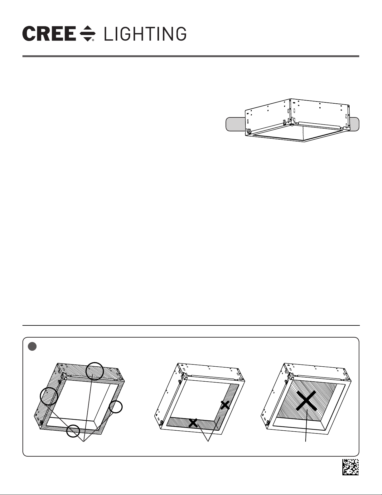
IMPORTANT NOTES:
• Do not screw any
additional screws into
the side or top of the
luminaire.
• Do not put pressure
on or hold by the
interior sidewalls.
This may damage the
optic. See Figure 1.
INSTALLATION INSTRUCTIONS
• Do not push on top of
the center lens. See
Figure 1.
• Do not lay the
luminaire on the
sensor on the front
face. See Figure 2.
• The Cadiant™ Dynamic Skylight
is for non-insulated ceiling
applications using T-bar ceiling
grid or in drywall applications only
when mounted on Cree Dr ywall
Grid Adapter DGA-22.
TO INSTALL:
1
CORRECT HANDLING
Handle the Cadiant™
Dyna mic Skylight Here
• Designed for use in
120-277VAC protected circuits
(fuse box, circuit breaker). Supply
wire sized in accordance with
national and local electrical wiring
codes rated 90C or higher
IMPROPER HANDLING-
Do NOT Handle Interior
Sidewalls
SIDEWALLS
IMPROPER HANDLING-
CENTER LENS
Do NOT Touch
Center Lens
1 of 3
LPN00647X0001A0_D
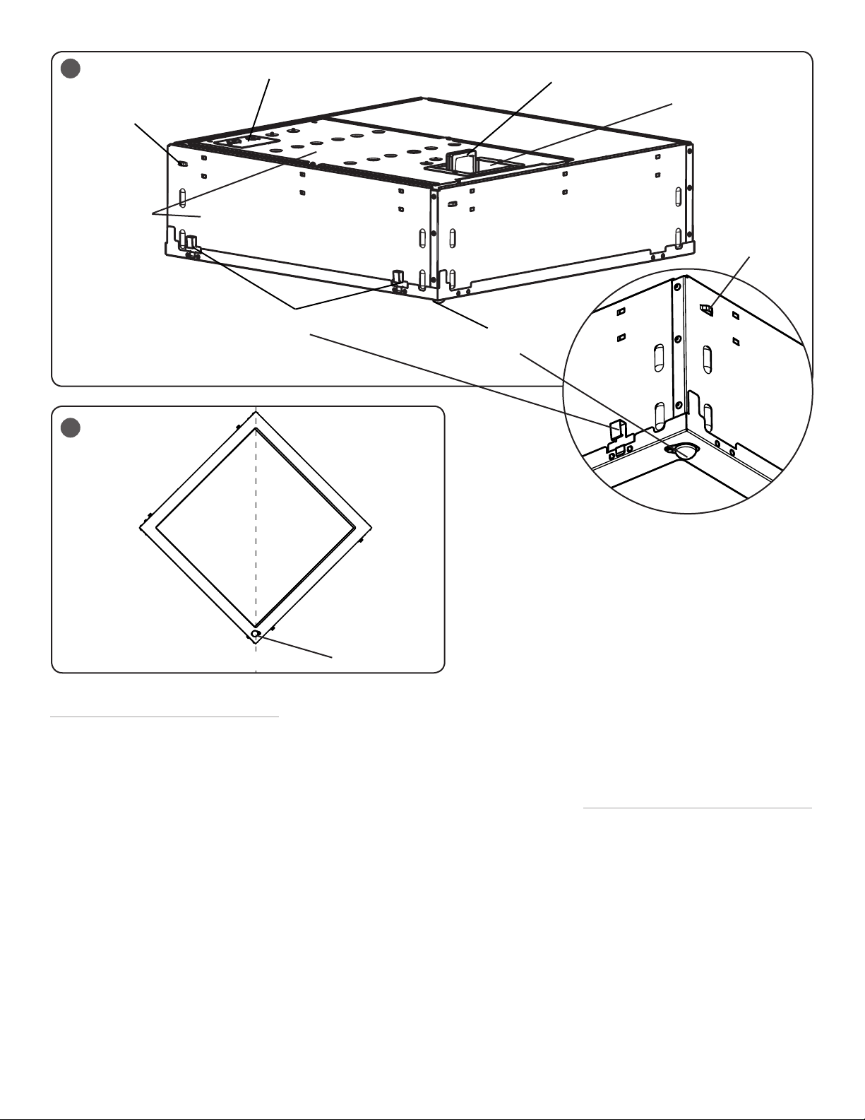
2
(4) Tabs For Safety
Wire Hangers
Do not screw any
additional scre ws into
the sid e or top of t he
luminaire.
3
WEST
Wiring Access Panel
(4) T-Bar Retention
Clips
EAST`
Sensor NEEDS TO BE
ORIENTED NORTH
RFM Module
Module Compartment
(4) Tabs For Safety
Wire Hangers
WEST
NORTH
TBAR CEILING INSTALLATION
NOTE: For secondary bracing
(recommended), locate tabs on the side of
the luminaire for safety wire hangers. See
Figure 2.
NOTE: DO NOT LAY THE CADI ANT™
DYNAMIC SKYLIGHT DOWN ON THE
SENSOR.
STEP 1:
Unpack the Cadiant™ Dynamic Skylight
from its shipping container being careful of
the sensor and not pinching the sidewalls.
STEP 2:
Bring the Cadiant™ Dynamic Skylight into
the T-Bar Ceiling panel and attach the
retention clips on the housing onto the T-Bar.
See Figure 2.
NOTE: To maintain the Cadiant™ Dynamic
Skylight experience,
sensor on luminaire is oriented as close
as possible to north. See Figure 2 and
3. For multiple luminaire installation, all
luminaires need to be facing the same
2 of 3
ensure that the
EAST`
Sensor
direction, with the sensor oriented as close
as possible to north.
NOTE: Ensure luminaries are securely
fastened to ceiling framing member by
mechanical means identified for use with
the luminaire and ceiling member type in
accordance with the NEC revision currently in
place with the Authority Having Jurisdiction
(AHJ) over the locale of the installation.
STEP 3:
Remove the wiring access panel by
removing the one Phillips head screw. See
Figure 2.
STEP 4:
Locate the RFM Module in the module
compartment and plug the module into
the RFM port located in the module
compartment. See Figure 2.
STEP 5:
Connect input conduit to access plate and
make wiring connections per the Electrical
Connection section.
STEP 6:
Push all wires back into the luminaire.
Re-secure cover with the provided Phillips
head screw.
DRYWALL GRID ADAPTER
INSTALLATION NOTES
NOTE: The Cadiant™ Dynamic Skylight
is also suitable for installation in drywall
applications ONLY when mounted in the Cree
Lighting Drywall Grid Adapter Kit model
DGA22.
STEP 1:
Installation of the luminaire should follow the
instructions provided in the DGA kit with the
following exceptions:
• Drywall installation employing the DGA
kit is for single luminaire installations
ON LY.
• Ensure the luminaire is independently
secured to ceiling framing members by
mechanical means using the provided
tabs for Safety Wire Hangers. See
Figure 2.
LPN00647X0001A0_D
 Loading...