

Page 1

EVOLUTION 100A
Integrated Amplifier
Instruction Manual
Rev 1.1
Page 2

Thank you for purchasing a Creek Audio EVOLUTION 100A Integrated Amplier. You are
now in possession of a State of the Art performance product. The functions and operation of
this integrated amplier are simple, however, the following notes are provided to explain all
aspects of its design and use. For simplicity we will now refer to the amplier as the ‘100A’.
Although this User Manual is intended to provide the latest instructions for use, it is possible
that a later version may be available to download from the Creek website.
Please check at www.creekaudio.com Go to the EVOLUTION 100A product page and click on
the tab marked Instructions.
UNPACKING AND LOCATING THE AMPLIFIER
When unpacking the EVOLUTION 100A please keep all the packing material in a safe place
for possible future use. In the carton there is a separate mains cable suitable for connecting
to the mains supply in the country of use. You will also nd a remote control unit and batter-
ies.
Make sure that the EVOLUTION 100A is on a suitable table, shelf or hi- equipment cabinet.
It is important to allow good ventilation to the heat-sinks inside the case. Avoid obstruction of
the ventilation slots on the top and bottom of the EVOLUTION 100A. It may be necessary to
place the EVOLUTION 100A on the top of other equipment, or a separate shelf to allow for
this. Do not place it at the bottom of a stack of equipment, as it may get too hot and switchoff, with an over-temperature warning on the display.
MAINS CONNECTION
IMPORTANT: Please check that the voltage selector switch on the bottom of the amplier
is set to the correct supply voltage for your region. Permanent damage can be caused by
using an incorrect setting.
The IEC socket end of the supplied cable should be rmly inserted into the connector on the
rear panel. Connect the mains plug to your AC outlet. Do not overload the mains outlet with
too many plugs or adaptors. The high quality performance of the 100A may be impaired if
the electrical supply to it is in poor condition. If in doubt, consult your hi- dealer, or a qualied electrician for advice.
The Mains Input connector on the rear panel is also tted with a fuse in a pull-out drawer.
The value of the 5 x 20mm cartridge fuse is clearly stated (T8AL 250V) next to the socket,
on the rear panel. This means it is a 8 Amp Time-lag (Anti-surge) type fuse, rated at 250V.
Always replace the fuse with one of identical rating to prevent the risk of re!
Page: 1
Page 3
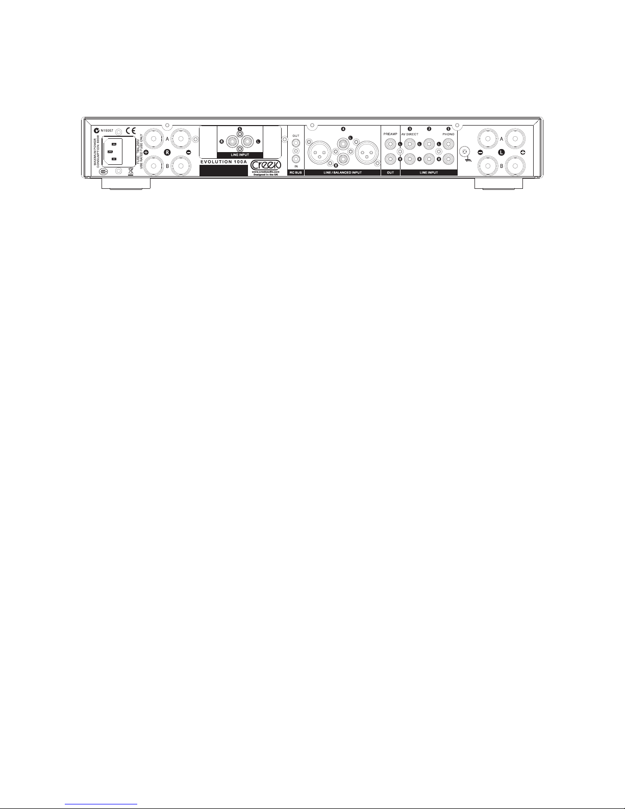
INPUT AND OUTPUT CONNECTIONS
On the rear panel there are 5 Line level* inputs labelled 1-5. Inputs 3 and 4 can be congured for different requirements and these options are described below. Input conguration
is controlled by a special menu which is available only during power-up, please see the
section below.
*Line level refers to a standardised way of transferring audio signals between equipment. It
is typically characterised by a voltage level of between 300mV and 2Vr.m.s. The 100A will
accept levels between 0 to 5.4V RMS and should therefore be compatible with all sources.
Line 1 is suitable for any line level source, such as CD, Tuner, Tape, etc. Line 1 can also
be congured for MM/MC Phono input. To congure for Phono input, an optional Creek
Sequel 40/48/54 mk2 pre-amp should be tted inside. See separate section below.
Line 2 is suitable for any line level source, such as CD, tuner, Tape, etc.
Line 3 is suitable for any line level source, such as CD, tuner, Tape, etc. Alternatively, Line
3 can be congured as AV Direct. This means the input passes the signal directly to the
100A’s power amp, bypassing the internal pre-amp and volume control.
AV Direct allows a multi-channel AV system to be integrated into your high quality 2-channel hi- system with ease. Simply connect the Line 3 input to your AV amplier’s Front L/R
pre-amplier output connections. The AV receiver must control the volume.
AV Direct makes it possible to “Slave” the amplier to another 100A using the pre-out connection, thus producing a bi-amplied system.
AV Direct also is the best choice for operating the 100A with the Creek EVOLUTION
50CD, DAC or Pre-amp, when its output is congured with digital volume control.
Line 4 is similar to Line 3, but offers either XLR or RCA input connectors. Do not use both
connection methods simultaneously.
*Balanced connections use a differential or symmetrical technique that is more resistant to
external noise and interference. It is ideal for preserving signal delity and low noise over
longer cable runs.
Page: 2
Page 4

Line 5 is suitable for any line level source, such as CD, tuner, Tape, etc.
Line 5 is mounted on a removable expansion port that allows for two optional upgrade paths:
In place of Line 5, it is possible to t an AMBIT Tuner, or RUBY DAC, which can be installed
by your dealer.
Pre-out is an output signal that duplicates the signal to the 100A’s internal power amplier
section. It is affected by all the controls of the amplier such as volume, tone, etc. and allows the user to drive another power amp if required. This can be used to “bi-amp” a suitably
equipped pair of loudspeakers or to connect an active sub-woofer for example.
CONFIGURING THE INPUTS
To access the input conguration menu the product must be switched off. Hold down the
MENU key whilst turning on the power and release once you see the “Setup Menu” appear.
Here you will see the options for input conguration and restoring factory defaults. The tree
looks like this:
Line 3 Options –
Line Level Input Default setting. The input is conventional.
Power Amp Input This bypasses the internal pre-amp giving “AV Direct” mode.
Line 4 Options –
Line Level Input Default setting. The input is conventional.
Power Amp Input This bypasses the internal pre-amp giving “Line 4 Direct” mode.
Factory Defaults Restores all settings to original factory states.
Navigate using the left-hand rotary control; pressing the control selects the option. Once
congured press the MENU key again and the product will start up with the new settings.
Headphone Output
Headphones can be used via the front panel Jack socket. It can be used alone or together
with loudspeakers.
Go to MENU and make the selection via the Headphone switch option. When headphones
are plugged in, a headphone symbol will show on the bottom left hand corner of the OLED
screen.
Page: 3
Page 5

ADDING THE INTERNAL PHONO STAGE OPTION
For added exibility, the Line 1 input on the EVOLUTION 100A can be used either for vinyl
disc (Phono) or line level. To listen to vinyl discs through the EVOLUTION 100A, it is necessary to t the optional Creek plug-in – ‘Sequel Phono’ board. Check with your dealer for
which version (MM40, MM 48 or MC54) suits your cartridge. When the Phono PCB is tted,
it will automatically indicate Phono on the display, when selected. Alternatively, Creek Audio
also produces a range of separate high-grade Phono pre-ampliers, which can be connect-
ed to any input.
A GROUND terminal post is provided on the rear panel to connect your turntables ground
wire if provided.
LOUDSPEAKER CONNECTIONS
The loudspeakers should be connected using a suitable pair of cables designed specically
for audio use. Check with your dealer for advice. The 100A’s high grade speaker terminals
allow for bare wire, 4mm plugs or spade lug connectors. Tighten the terminal fully after tting
the loudspeaker wire. Please consult your dealer for advice if you are unsure.
It is very important to connect the loudspeakers with the correct phase. Cables are normally
polarised with a line or writing on the positive side to assist in this. Connect the red (or ‘positive’ or ‘+’) terminal of your loudspeaker to the red terminal of the amplier and likewise for
the black. If both channels are not connected with the same polarity, a severe loss of bass
performance and lack of stereo image will result.
It is very important not to short-circuit the loudspeaker cables together when the 100A is
powered-on, as permanent damage may result. Ensure there are no strands of cable bridg-
ing the terminals when connecting the loudspeakers and make all connections with the 100A
turned off. If it is necessary to change or move the location of the loudspeakers, make sure
that you rst turn-off the 100A and then re-check the wiring once nished.
Speakers A and B
The 100A is capable of connecting two pairs of speakers and controlling them with the front
panel menu or remote handset. To select speakers A, B, A+B, or no speakers, press the
menu button on the front panel and scroll down to Speaker Selection. Press the left hand
input selector to bring-up the options. Rotate the left hand knob to choose the option you
require. The display will revert to normal after a few seconds. This can also be done with the
two blue buttons on the remote marked Speakers A and B.
REMOTE IN/OUT
All EVOLUTION 50/100 products are equipped with remote control input and output jacks to
allow the use of external infra-red (IR) sensors . Check with your dealer for more info.
Page: 4
Page 6
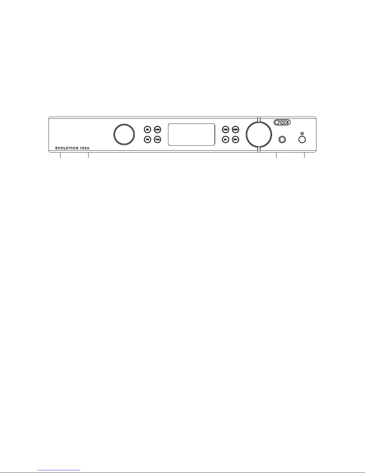
OPERATING THE EVOLUTION 50A
The front panel controls, from left to right, feature a rotary Input selector knob, a group of
4 buttons marked SRC, PRE, TUNE, and BAND for the tuner, if tted. Next is the OLED
display window, then 4 more buttons marked TONE, MENU, BAL and INFO. The volume
control, headphone socket and Power on/off switch complete the line-up.
NOTE: All control settings are memorised, even after the power is turned off.
Turn on the power using the push-button on the right-hand side of the product. The display will show the Creek logo whilst the internal electronics are congured and allowed to
settle. The amplier is ready for use once the display changes to show selected input and
volume settings.
The input is selected by the left-hand rotary control: rotate the control until the desired
input is shown in the display. The inputs can also be chosen using the remote control.
The volume can be adjusted via right-hand rotary control on the front panel or remotely
with the EVO remote handset. Pressing the volume knob will mute the signal; pressing or
turning the knob clock-wise will un-mute the signal.
If the volume is adjusted between -9dB to 0dB and then muted, the level will be reduced
to -10dB when un-muted. The maximum attenuation from the electronic volume control is
-80dB. If the volume knob is turned below this level it will mute the output.
It is important to note that the power output of the amplier is the product of both the volume setting AND the input signal level from the source equipment. Sources with a lower
output signal will require a higher volume setting to reach the same loudness. Do not be
worried if you nd the volume is approaching 0dBs to achieve the required listening level, it
does not necessarily mean the amplier is working harder or delivering its full capability.
The current volume setting is stored during power off but when the 100A is turned back on,
the value will be limited to a maximum level of -20dB, to prevent unexpected loud sounds
from being produced.
The MENU button offers some set-up options to tailor the operation of the 100A to your
preference. Pressing this button will reveal 3 options which can be highlighted using the left-
hand rotary control. Depressing the rotary control will select the highlighted option to reveal
further options. The options tree looks as follows:
Page: 5
Page 7

Display Settings Always On The OLED display will be lit at all times the product is operating
Auto Off The OLED display will go out after a short delay
Display Brightness Full Maximum screen brightness
Medium
Low Lowest screen brightness
Headphone Switch -
Disable Speakers Inserting a headphone jack will mute the loudspeaker outputs
Simultaneous Use Both loudspeakers and headphones will be active simultaneously
Congure the product to your taste by selecting the desired options with a press of the lefthand rotary control. Use the MENU key to exit.
The BAL (Balance) button allows adjustment of the relative levels of left and right channels.
This is used to compensate for non-ideal loudspeaker placement or to isolate one channel
of the audio signal. Once the BAL button has been pressed, the right-hand rotary control
adjusts the balance and the relative level difference is shown on the display. To quickly reset
the balance to Centre simply press BAL and then press the volume control before the display changes back to normal. The characteristic of the control has been tailored to maintain
the same perceived volume level from the system in order to allow easy adjustment.
The TONE button allows relative Bass and Treble levels to be adjusted if required. To maintain optimum sound quality, the tone control circuits are normally bypassed; to activate them
simply press and hold the TONE button until the display indicates “Tone On”. Pressing the
TONE button now cycles through Bass, Treble and Volume options. Adjust tone with the
right-hand knob and to reset the value to zero quickly, press TONE and then Volume before the display reverts to normal. To completely disable the tone circuits, press and hold
the TONE button until the screen indicates “Tone Off”. Tone settings are remembered even
when the controls are bypassed.
HEADPHONES
The 100A uses a dedicated headphone amplier to provide a low impedance output signal
to the jack socket on the front panel. This is supplied by the pre-amp and therefore, if you
select AV Direct for Line input 3 or 4, the signal will bypass the pre-amp and pass directly
through to the power amp, so no signal will be available to the headphones.
PROTECTION
The 100A has short circuit (over-current), over-temperature and DC offset protection. The
internal loudspeaker relays will isolate the output under any of these conditions to avoid potential damage to the speakers and the display will indicate the cause.
Page: 6
Page 8

The loudspeakers will be re-connected after a short delay and only if the fault has been
cleared.
Over temperature
If the 100A has over-heated, it may indicate the top of the case is not properly ventilated. If
so, make sure the amplier is not located inside a cupboard or placed under other equipment. It may also mean the amplier has been driving low impedance loudspeakers at a
high level for a long period, gradually causing the temperature to rise. The temperature of
the internal heatsink is monitored by a sensor and can be checked in a start-up INFO. Press
INFO and then power the amplier on. The display will show the heatsink temperature in
centigrade only.
Over current
If there has been a short circuit of the loudspeaker wiring, the 100A will immediately disconnect the output. To clear the fault, switch off the amplier and check the speaker wiring for
shorts. Alternatively, the loudspeaker you are trying to drive may be unsuitable due to being
too insensitive or having very low impedance. The EVO 100A is capable of driving a 2 ohm
load to clipping, before the over current protection is engaged.
DC offset
If the ‘DC presence’ warning is displayed, it may be due to an internal fault with the amplier
or could be triggered by severe clipping (overload) of the amplier. The output is disconnected to avoid potential damage to loudspeakers. If the condition clears by itself, try reducing
the volume setting. Never drive your amplier to levels which cause audible distortion. This
is an indication that either the amplier or loudspeakers are being pushed beyond their capabilities and may result in permanent damage.
POWER CONSUMPTION
It is appreciated by Hi-Fi enthusiasts that leaving equipment powered up continuously can
improve the performance. However, this small improvement in sound quality comes at the
expense of continuous power consumption from the mains, which will increase your electricity bill and also reduced working life of the product. The 100A draws approximately 20 Watts
of power when switched on and not producing a signal.
We recommend switching the 100A off at the front panel if it’s not going to be used for a
prolonged period of time. Normal performance is achieved in a very short period of time due
to the advanced circuitry in the 100A amplier.
Relay switches are used to route signals inside the 100A and these produce a mechanical
click sound when they operate; this is normal and does not indicate a malfunction with the
product.
Page: 7
Page 9

REMOTE CONTROL
The 100A’s remote control handset allows the user to
operate the amp and CD/DAC/Pre and tuner functions.
It should be noted that the EVO remote handset will
only operate Creek’s EVOLUTION 50 and 100 ranges
of products and is not able to switch the mains power
on or off.
The operation of the remote is designed to be intuitive.
However, to select Amp, CD, tuner and DAC functions
it is necessary to press the appropriate button at the top
of the remote rst.
FIRMWARE
It is possible to check the rmware status of your 100A
on its display. Turn off the amp and hold down the INFO
button, then power-up the 100A. Once the screen has
nished displaying the Creek logo it will switch to “About
this unit”. The rmware version will be displayed along
with the temperature of the internal heatsink.
RADIO INTERFERENCE
The EVOLUTION 100A is designed to work properly
in normal domestic operating conditions. However, its
performance could be affected if sited near to a radio
transmitter such as a mobile phone, etc. Relocating the
100A or the radio transmitter will normalise the situation.
Page: 8
Page 10

FINAL WORDS
The EVOLUTION 100A is designed to provide years of reliable use. If you need more assistance, it is always advisable to go back to the supplying dealer for their expert help. If you
are unfortunate enough to need service work to be carried out on your 100A, it should be
returned to your dealer in the original packing material if possible.
Creek Audio Ltd reserves the right to change or modify the specication of its products with-
out prior warning.
WARRANTY
If within two years of date of purchase, your EVOLUTION 100A proves to be defective for
any reason other than accident, misuse, neglect, unauthorized modication, or fair wear and
tear, Creek Audio Ltd. will, at its discretion, replace the faulty parts without charge for labour
or return carriage within the United Kingdom.
This warranty is valid only in the United Kingdom only and given in addition to statutory
rights.
Service enquiries outside the United Kingdom should be addressed to the supplying dealer
rst or the Creek distributor/importer.
For list of distributors, please visit: www.creekaudio.com/distributors/
Warranties granted in these countries are entirely at the discretion of the distributor.
Page: 9
Page 11

Technical Specications:
Power output @ 1% THD >110 Watts into 8 Ohms, both channels driven
Power output @ 1% THD >170 Watts into 4 Ohms, both channels driven
Continuous output current >8.5A (sine wave)
Peak output current, burst into 0.5 Ohms +/-26 Amps, current burst into 0.5 Ohms
THD and Noise, 2/3 rated power 8 Ohms <0.002% 20 Hz to 20 kHz
Signal to Noise Ratio 102dBA Line input
Frequency Response <10Hz to >100 kHz +/-2dB
Gain at 1 kHz Un-balanced 33.3dB (x 48)
Gain at 1 kHz Balanced 27.0dB (x 22.5)
Input sensitivity, Line level 810mV
Maximum input voltage, RCA and Balanced (XLR) 5.4V and 10.8V r.m.s.
Crosstalk -80dB at 1 kHz
DC offset < +/-10mV
Pre-Amp Inputs 5 x RCA un-balanced, including optional
Plug-in Phono options Input 1 changes to Phono with Sequel Phono tted.
Gain: 40, 48 or 54dB
Power amp inputs Inputs 3 & 4 can be assigned as
Power Amp direct inputs
Tuner option AMBIT Tuner module (optional extra)
DAC option RUBY DAC module (optional extra)
IR BUS For adding an external IR sensor or linking to an
other product.
Loudspeaker Outputs A+B x2 pairs of high-grade 4mm binding posts
Headphone Output x1 x 6.3mm jack socket with dedicated low imped
ance headphone amp (<50 Ohms)
Output impedance <0.05 Ohms 20Hz to 20 KHz
Mains voltage 230/115V 50/60Hz, switchable
Front panel nish options Silver or Black
Power Consumption: Idle, Max, Standby <20 Watts, 600 Watt, No standby
Weight net 9kgs (20 lbs)
Size W/H/D inc. feet and knobs 430 x 60 x 280mm (17 x 2.3 x 11”)
Page: 10
Page 12

Creek Audio Ltd
12 Avebury Court, Mark Road, Hemel Hempstead, Hertfordshire, HP2 7TA England
www.creekaudio.com - [email protected] - +44(0)1442 260146
 Loading...