

Cree FLEX Series, FLEX FLX24, FLEX FLX14, FLEX FLX22 Commercial Specification
FLEX Series with Cree SmartCast® Technology
Commercial Specification Troffers with Emergency Driver
Includes: FLX14™, FLX22™ and FLX24™
INSTALLATION INSTRUCTIONS
IMPORTANT SAFEGUARDS
When using electrical equipment, basic safety precautions should
always be followed including the following:
READ AND FOLLOW ALL SAFETY
INSTRUCTIONS
1. DANGER- Risk of shock- Disconnect power before installation.
DANGER - RISQUE DE CHOC - COUPER L’ALIMENTATION
AVANT L’INSTALLATION
2. CAUTION – Installation and servicing should be performed by
qualied personnel only. De-energize before opening.
ATTENTION – L’installation et l’entretien doivent être effectués
par du personnel qualié seulement. Mettre hors tension avant
l’ouverture
3. To reduce the risk of electric shock, disconnect both standard
and emergency power supplies and converter connector of the
emergency driver before servicing.
Pour réduire le risque de décharge électrique, vous devez
déconnecter à la fois le disjoncteur divisionnaire ou les fusibles et
les alimentations d’urgence avant l’entretien.
4. Do not use outdoors.
Ne pas utiliser à l’extérieur.
5. Do not let power supply cords touch hot surfaces.
Ne laissez pas les cordons d’alimentation toucher les surfaces
chaudes.
6. Do not mount near gas or electric heaters.
Ne montez PAS près des appareils de chauffage de gaz ou
électriques.
7. DO NOT use this equipment for other than its intended use.
NE PAS utiliser cet équipement à d’autres ns que celle qui est
prévue.
8. Equipment should be mounted in locations and heights where it will not readily be subjected to tampering by unauthorized
personnel.
L’équipement doit être monté dans des endroits et à des hauteurs où il ne sera pas soumis à des altérations par des personnes
non autorisées.
9. The use of accessory equipment not recommended by the manufacturer may cause an unsafe condition.
L’utilisation d’accessoires non recommandés par le fabricant peut causer une situation dangereuse.
10. Suitable for suspended ceilings.
11. Max. mounting height: 15 ft.
Hauteur de montage max.: 15 pieds.
12. Access above ceiling required. Do not install insulation within 3” (76mm) of any part of the luminaire.
Accès requis au-dessus du plafond. Ne pas mettre l’isolant à moins de 3 po (76 mm) de toute partie du luminaire
13. Suitable for suspended ceilings.
Convient aux plafonds suspendus.
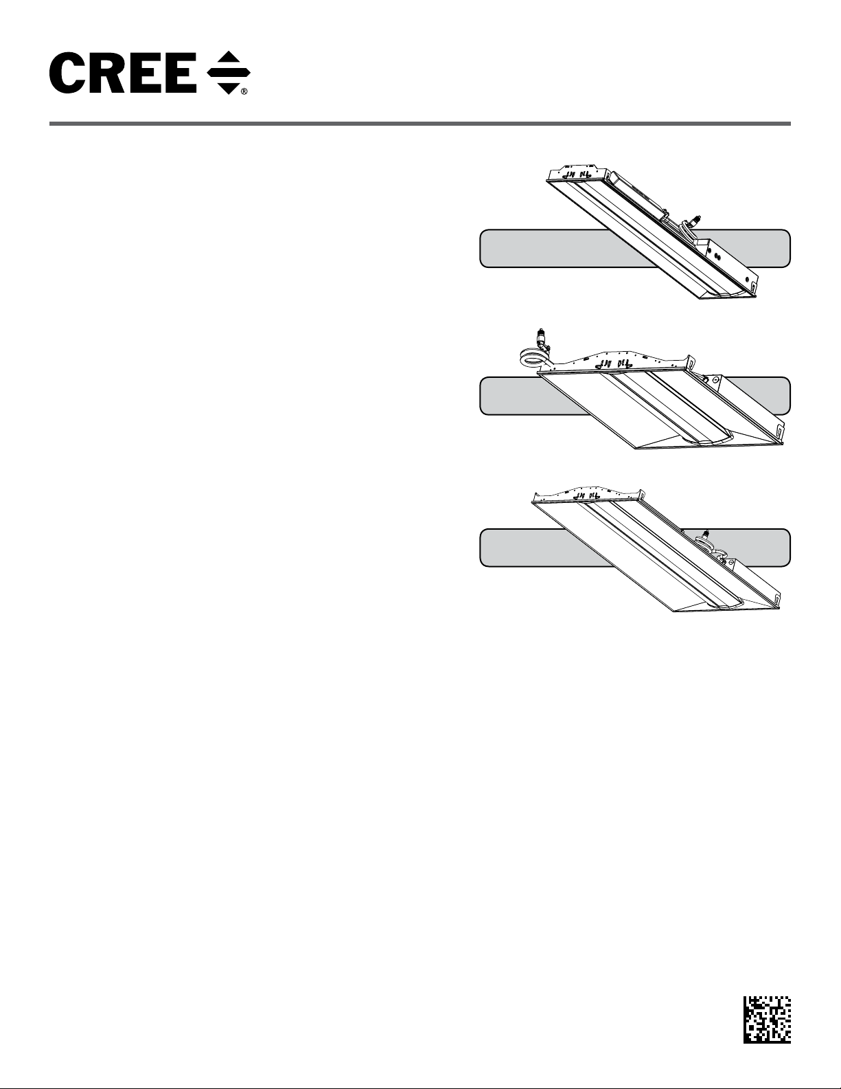
FLX14™
FLX22™
FLX24™
SAVE THESE INSTRUCTIONS FOR FUTURE REFERENCE
• The FLEX Series of specification troffers is for non-insulated
ceiling applications using T-Bar ceiling grid, dry wall grid adaptors,
and suspended mount.
• Designed for use in 120-277V 50-60 Hz or 347V 60Hz protected
circuit (fuse box, circuit breaker). Supply wire sized as per NEC or
governing code(s), 90C rated.
1 of 4
• Make sure to cap off all unused leads.
• Lens and removable end cap may shift during installation. To seat
lens press end caps and squeeze lens to engage with back panel.
LPN00611X0001A1_C
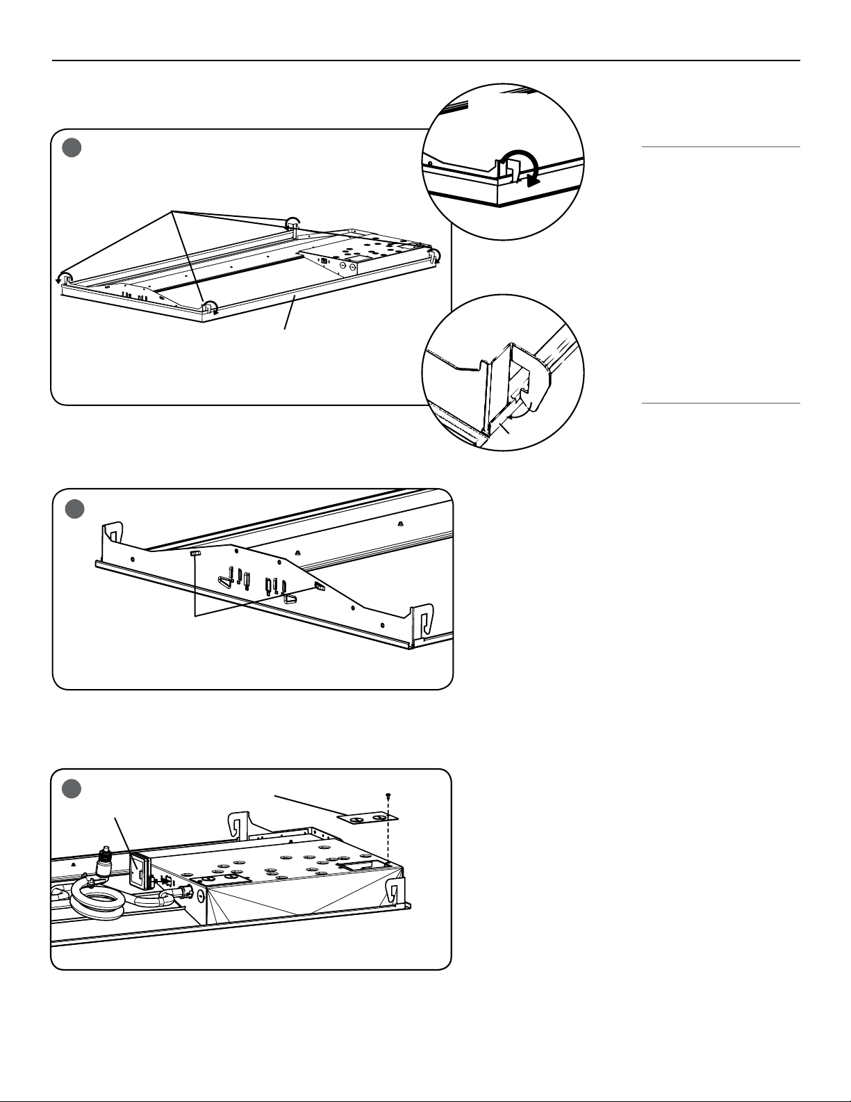
TO INSTALL:
1st:
90° Bend
1
T- BAR CEILING MOUNTING
STEP 1:
Bring the FLEX troffer up into
Luminaire Hooks
2nd: Bend
T-bar
Against T-bar
T-bar
2
Cable Slots
the T-Bar grid.
STEP 2:
Locate the luminaire hooks and
bend them out 90 degrees for
installation. See Figure 1.
NOTE: The luminaire hooks ship
bent in and need to be bent out
for installation.
STEP 3:
Then bend the luminaire hooks
against the T-Bar to secure the
luminaire. See Figure 1.
SUSPENDED MOUNTING
STEP 1:
Attach customer supplied
cables to the (2) cable slots on
each side of the housing. See
Figure 2.
STEP 2:
Attach customer supplied
cables to mounting surface
using customer supplied
hardware. Ensuring that
mounting surface can support
the luminaire.
STEP 3:
Attach the RF Module to the
luminaire by clicking it into
place as Shown in Figure 3.
2 of 4
3
RF Module
Power Supply
Junction Box Cover
LPN00611X0001A1_C
 Loading...