

CREE CRF-22010-TB Datasheet
CRF-22010-TB
© Cree, Inc. 2003 Specifications subject to change without notice
Rev 1.01 - March 28, 2003 http://www.cree.com/
Evaluation Board for CRF-22010
Version A (Narrowband)
Features
• Ready-to-Go RF Amplifier
• Requires Two Power Supplies
• Externally Adjustable Gate Bias Voltage
• Solderless Transistor Changeout
• Includes Heat Sink, Fan, and Wiring Harness
• Designed for Narrowband Operation
Description
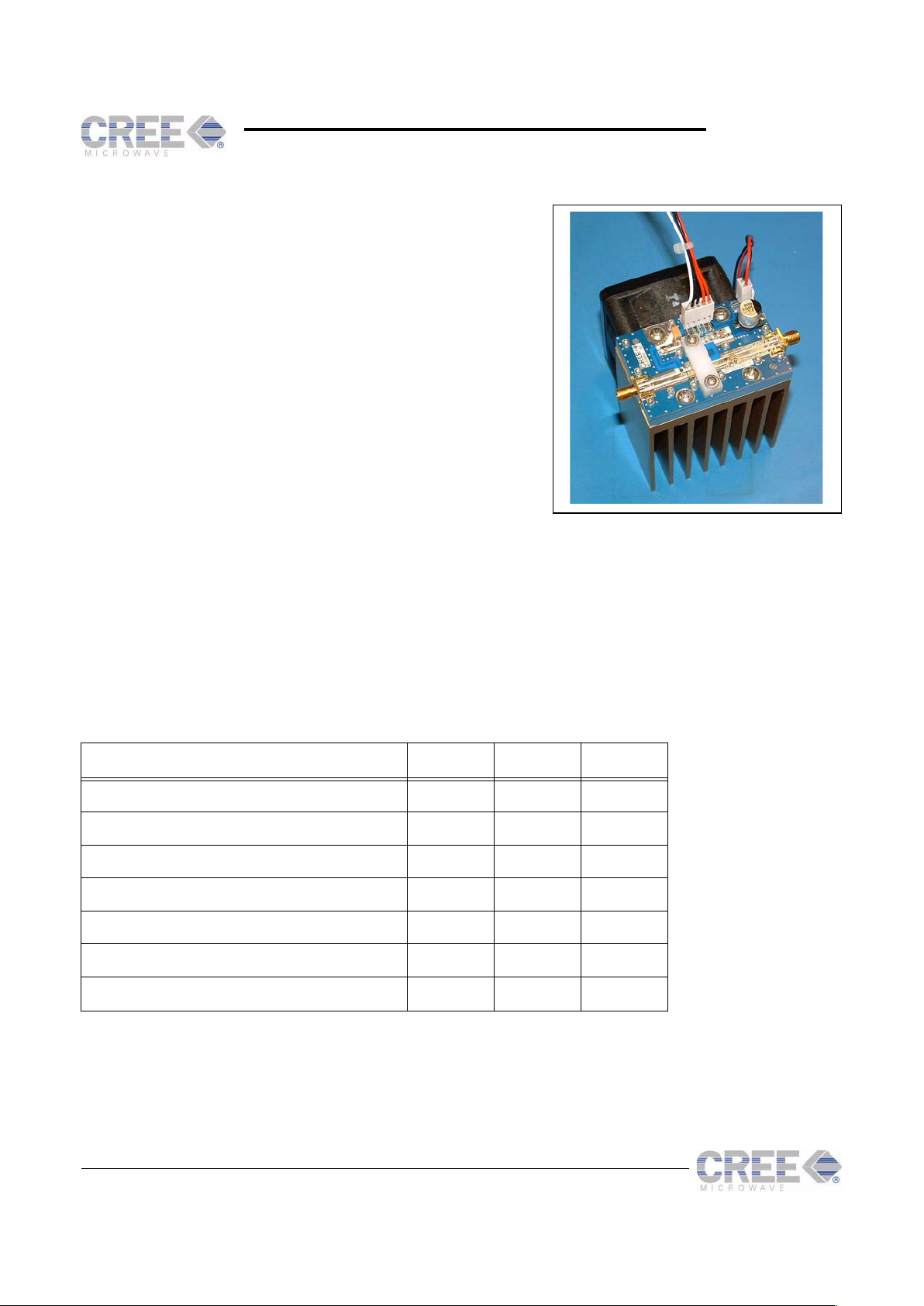
Cree’s CRF-22010-TB-A is a complete 10 watt RF single band power amplifier. The evaluation board is pretuned
for a specified frequency (generally between 1.8 and 2.2 GHz) and is supplied with CRF-22010 silicon carbide
MESFETs in the 101 style flange-mount package. The CRF-22010-TB-A requires a positive 48 VDC drain power
supply and a negative adjustable gate power supply (capable of providing up to -15 VDC) for operation. This board
will assist the designer in testing and evaluating the CRF-22010.
1
Amplifier and carrier without heatsink and fan assembly
Absolute Maximum Ratings (not simultaneous) at 25°C
Parameter Symbol Rating Units
Drain Supply Voltage V
DSMAX
50 VDC
Drain Supply Current I
DSMAX
+2 ADC
Gate Supply Voltage V
GSMAX
-15 VDC
Gate Supply Current I
GSMAX
0.1 ADC
Total Device Dissipation P
D
66 W
Storage Temperature T
STG
125 °C
Thermal Resistance, Junction to Base
1
R
qJB
4.5 °C/W
CRF-22010-TB
© Cree, Inc. 2003 Specifications subject to change without notice
2 http://www.cree.com/
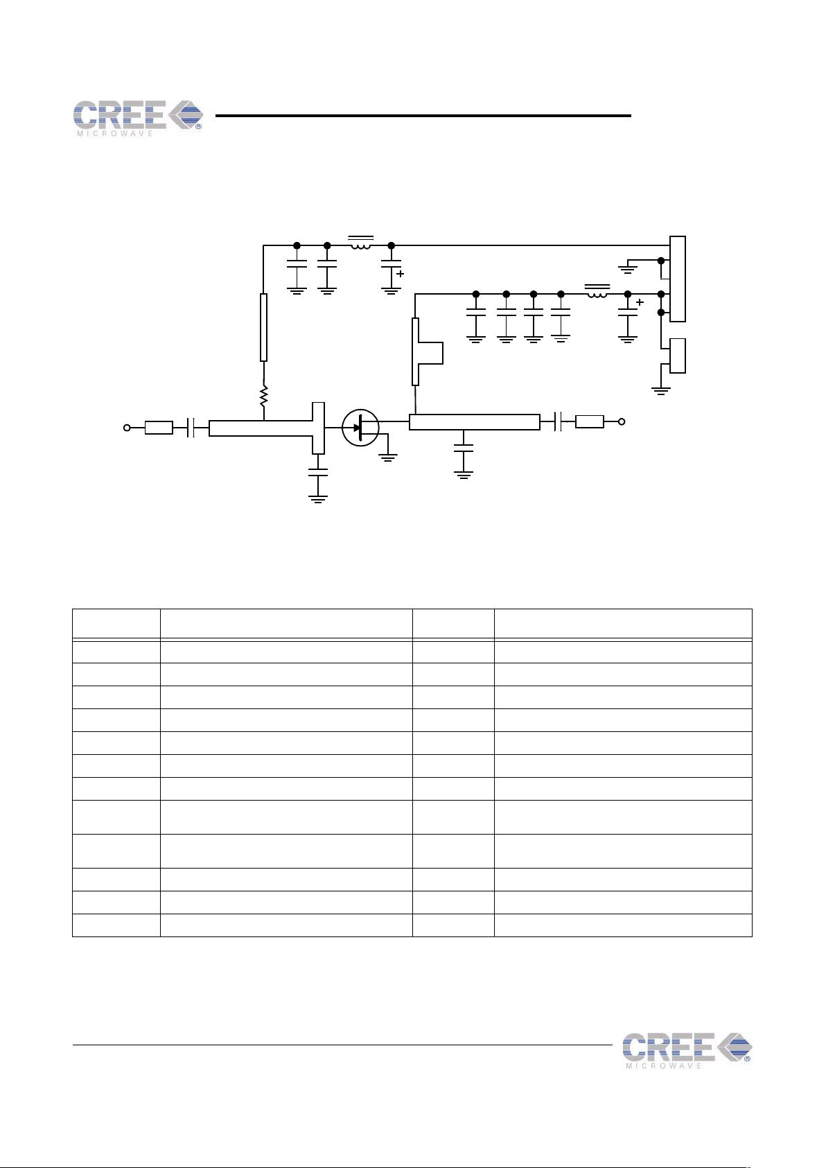
Schematic (Rev. A)
Parts List
Note: Some values may differ due to substitution in the event of temporarily unavailable parts
Designator Value Designator Value
R1 39 W, 0.1 W, 0805 Chip Resistor C1, C2, C3, C6 27 pF, 100V Ceramic Capacitor, ATC 12061C104MAT2A
L1 Ferrite, 80 ohms, Steward HI1206K101R C4 0.1 uF, 25V, 0805 Ceramic Capacitor
L2 Ferrite, Murata BLM21P220SG C5 10 uF, 25V Tantalum Capacitor
J1, J2 Flange Mount SMA Female Connector C7 2.2 nF, 100V Ceramic Capacitor, AVX 08051C222MAT2A
J3 5-pin Molex Male Connector C8 10 nF, 100V, 0805 Ceramic Capacitor
J4 2-pin Molex Male Connector C9 0.1 uF, 100V, 1206 Ceramic Capacitor
Q1 CRF-22010 C10 33 uF, 100V, Aluminum Electrolytic Capacitor
Substrate Rogers RO4003, e
r
=3.38, h=32 mil C11 3.3 pF, 150V Porcelain Capacitor, ATC
100B3R3OBW500X (exact value depends on tuning)
Heatsink Thermalloy 74605 Extrusion, 2 in long C12 2.2 pF, 150V Porcelain Capacitor, ATC
100B2R2OBW500X (exact value depends on tuning)
Fan Comair-Rotron FS48B3, 60 mm, 48V, 0.05 A, 18 cfm
V_DD
C1
C2
C3
C6 C9
C8
L1
C10
J4
J3
C7
C11
C12
C5
L2
J1
RF
IN
J2
RF
OUT
Q1
R1
V_GG
C4
FAN+
FAN-
GND
GND
V_DD
2
1
5
4
3
2
1
 Loading...