

Page 1
INSTALLATION GUIDE
HOW TO POSITION AND PROGRAM THE FLASH PROGRAMMER 2S
PRODUCT FUNCTIONS
• Centralised programming for two heating zones
using two temperature modes:
- Comfort temperature
- Reduced temperature
• Manual override function in comfort and reduced mode for each room.
PRINCIPLE OF OPERATION
• Convectors equipped with a suitable electromechanical thermostat:
Reduced temperature obtained by supplying a resistance, which overrides the sensing element of the
thermostat.
• Convectors equipped with a suitable electronic thermostat:
Reduced temperature achieved by delivering an alternating signal (coding adopted by all designers since
January 1994)
TECHNICAL CHARACTERISTICS
• Time switch: Electronic clock with day and week programs.
• Power backup: By lithium battery, backup guarantee for a total of 3 years minimum against mains failure
(battery life: 10 years)
• Program increments: 1 minute
• Number of zones: 2
• Total maximum current rating: 0.5A
• Dimensions: 167mm x 84mm x 44mm
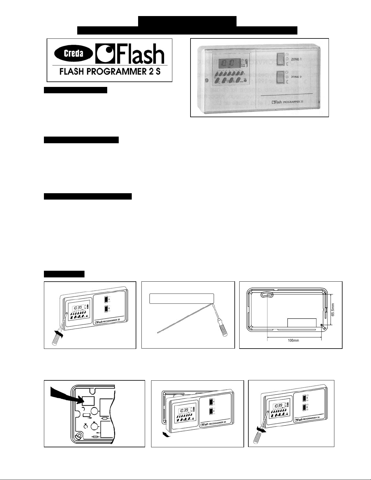
INSTALLATION
1 Unscrew the time switch fixing
screw
4 Electrical connections (see page 2)
IMPORTANT Insert the flying
lead from the display panel into the
socket on the circuit board as shown
2 Separate the base plate from
the casing using a screwdriver
5 Put outer casing back on
3 Surface-Mounted base with 2off
screw fixings Ø3mm maximum
6 Put back in and tighten the
time switch fixing screw
1
Page 2
CONNECTING THE PILOT WIRE
Whether mechanical or electronic, regardless of make, since January 1997, the reduced mode of a thermostat
which can be programmed via pilot wire, is achieved by transmission of an alternation signal via the pilot wire
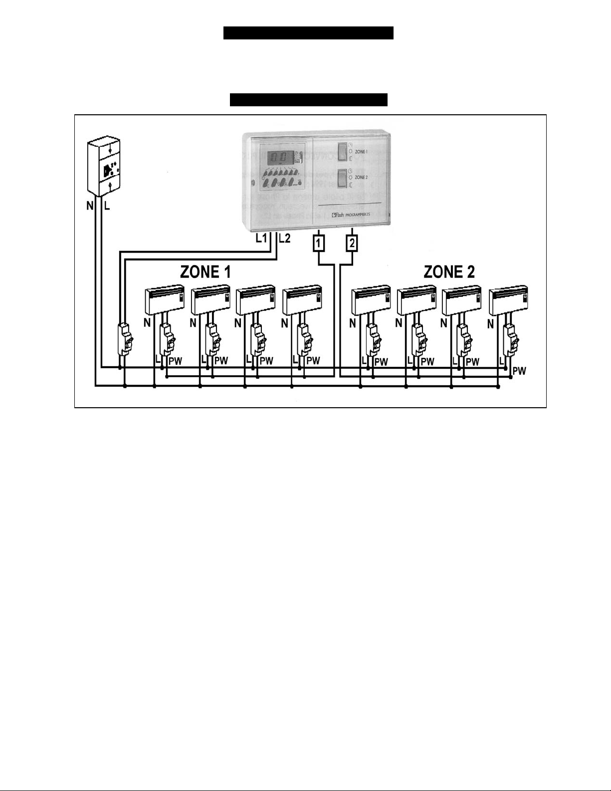
ELECTRICAL CONNECTIONS
FOR PILOT WIRE CONVECTOR HEATERS
1. All types of convectors since 1994:
The pilot wire carries the live current to the convector Inputs: connect neutral to L1 and “Live” to L2
2. Convectors before January 1994:
Check the convector instructions or if you have none, consult the manufacturer. In certain cases, the pilot
wire carries the neutral current to the convector inputs. In this event, connect neutral to L2 and “Live” to L1.
2
Page 3
USER GUIDE
WHY A PROGRAMMER
• FOR GREATER CONTROL OF YOUR COMFORT:
• FOR GREATER CONTROL OVER YOUR ENERGY COSTS:
PRINCIPLE OF OPERATION
FLASH PROGRAMMER 2S ALLOWS YOU TO PROGRAM TWO HEATING ZONES
Example:
THE TIMES YOU PROGRAM FOR EACH ZONE DEFINE THE COMFORT HEATING TIMES AND THE
REDUCED HEATING TIMES
• Comfort Temperature
Individually for each room.
• Reduced Temperature : The temperature you want in the house when you are away or at night
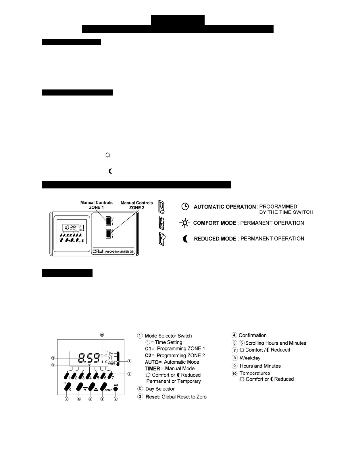
MANUAL OPERATION FOR EACH INDIVIDUAL ZONE 1 AND 2
HOW TO PROGRAM AND USE THE FLASH PROGRAMMER 2S
- The temperature you need at a time that suits you.
- Slightly lowering the temperature during the night or when you are not at home can achieve
substantial savings.
- Day zone for the dining room, living room etc
- Night zone for the bedroom etc
: The temperature you want in the house when you are at home, which can be set
PROGRAMMING
The dual zone time switch allows you to program 20 comfort or reduced switching times spread anywhere over
the two zones.
e.g. 12 switching times for zone 1 and 8 for zone 2.
Each switching time can be applied to one or several days of the week.
e.g. comfort mode from Monday to Friday at 7.00 represents one switching time. You now have 19 left.
3
Page 4

BEFORE PROGRAMMING YOUR FLASH PROGRAMMER 2S
TAKE TIME TO WRITE YOUR PROGRAM IN THE TABLES BELOW
ZONE 1 (The first lines are filled with an example)
ZONE 1 C1 Times Mon 1 Tue 2 Wed 3 Thu 4 Fri 5 Sat 6 Sun 7
Comfort
Example
Reduced
Example
Comfort :
Reduced :
Comfort :
Reduced :
Comfort :
Reduced :
Comfort :
07:00
08:00
Reduced :
Comfort :
Reduced :
ZONE 2 (The first lines are filled with an example)
ZONE 2 C2 Times Mon 1 Tue 2 Wed 3 Thu 4 Fri 5 Sat 6 Sun 7
Comfort
Example
Reduced
Example
Comfort :
Reduced :
Comfort :
Reduced :
Comfort :
20:00
23:00
4
Reduced :
Comfort :
Reduced :
Comfort :
Reduced :
Page 5

1. SETTING THE TIME
2. PROGRAMMING
5
Page 6

6
3. AUTO MODE
4. CHECKING SWITCHING TIMES
Page 7

5. MODIFYING OR CANCELLING SWITCHING TIMES
7
Page 8

6. PERMANENTLY OVERRIDING “TIMER” MODE
7. TEMPORARILY OVERRIDING “TIMER” MODE (HOLIDAYS etc)
8
APPLIED ENERGY PRODUCTS LIMITED
MORLEY WAY, PETERBOROUGH PE2 9JJ
TEL +44 (0) 01733 456789 / FAX: +44 (0) 01733 310606
Website: www.creda-heating.co.uk
(Leaflet No. 22671AA Revision. A)
 Loading...