

Page 1
8
Full details of terms and conditions are available on request from:-
APPLIED ENERGY PRODUCTS LIMITED
MORLEY WAY, PETERBOROUGH PE2 9JJ
TEL: +44 (0) 844 372 7761
FAX: +44 (0) 844 372 7762
Website: www.applied-energy.com
(A4 Leaflet No. 555-2071-59b)
AQUABLUE
CREDA AQUABLUE
ELECTRIC SHOWER
Installation and User Guide
IMPORTANT:
This booklet should be left with the user after
installation and demonstration
Page 2
2
Contents
Information for the installer
Fixing the Shower to the wall . . . . . . . .
Plumbing . . . . . . . . . . . . . . . . . . . . . . . .
Electrical . . . . . . . . . . . . . . . . . . . . . . .
What to do if things go wrong . . . . . . . .
Assembly of Accessories . . . . . . . . . . .
Guarantee and contact details . . . . . . .
Page
2
3
4
6
7
8
Contents
Information for the user
How to use your Creda Shower . . . . . .
How to maintain your Creda Shower
. .
What to do if things go wrong . . . . . . . .
How your Creda Shower works . . . . . .
Creda After Sales Service . . . . . . . . . .
Guarantee and contact details . . . . . . .
Page
5
5
6
7
7
8
Installation Instructions .
ALL WIRING AND INSTALLATION MUST BE SUPERVISED BY A SUITABLY QUALIFIED PERSON.
WARNING: DO NOT INSTALL THIS SHOWER IN A ROOM WHERE IT MAY BE SUBJECT TO FREEZING.
We recommend that the installation is done in the following sequence.
a. Fixing the shower to the wall b. Plumbing c. Electrical connections
a. Fixing the shower to the wall
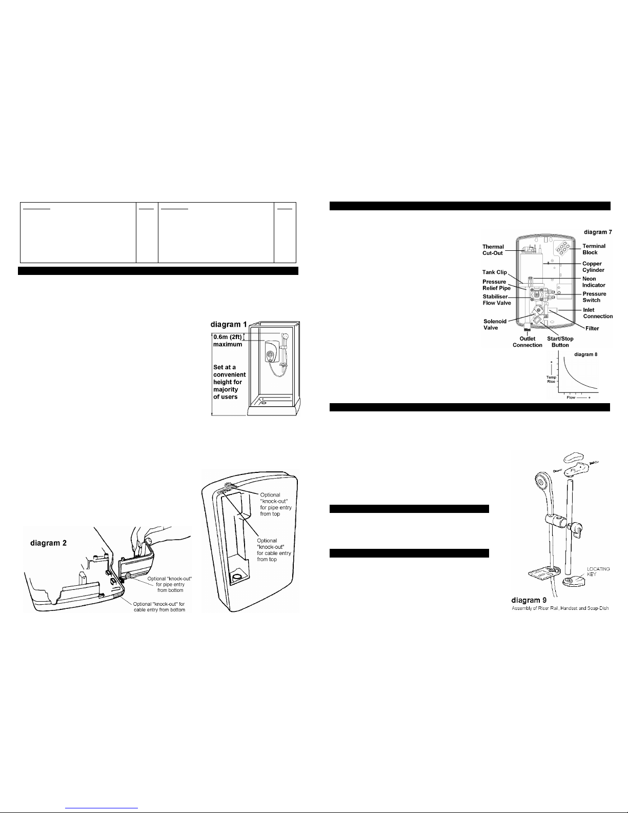
1. Position the riser rail at a height convenient for majority of users
as detailed in diagram 1 and mark its position.
2. Position the heater so that the top of the unit is horizontal and
level with, or up to 0.6 metres (2ft) maximum below the top
of the riser rail.
Choose a flat piece of wall to avoid the possibility of distorting
the backplate, as this may make the front cover a poor fit.
3. Adjust the position to get the most convenient arrangement
taking the following into account.
• The heater must not be mounted in the direct spray from
the handset.
• The handset must not be able to come into contact with used water in the cubicle, bath or basin.
If it can, then a vacuum breaker must be fitted.
4. Fix the riser rail with suitable screws.
The fixing holes at the base of the brackets will be disclosed by removing the
plastic fronts.
(See diagram 9).
5. Decide the position of the electrical cable to the unit.
If top or bottom entry is chosen (according to diagram 3),
cut away the walls in the backplate as shown in diagram 2.
6. Decide the entry position of the cold water pipe into the unit.
If top, cut away the backplate.
If rear, please read the section on plumbing.
If bottom, remove the front cover (complete with knobs),
and cut away the detachable corner section as shown.
7
How your Creda Shower Works s
Your shower is designed for convenience, economy and safety of use.
1. Water is heated instantaneously as it flows over the heating elements in the copper cylinder (diagram 7)
2. The heaters are only switched on when sufficient water is flowing.
This is done automatically with a switch, which works on water pressure.
3. The water is turned on and off by the solenoid valve
built into the shower. This is switched on by button “B”.
4. The flow of water is automatically held at the level set
by the user even though the supply pressure may vary.
5. If the water supply falls below a set limit, the pressure
switch will operate switching off the power to the elements.
6. As a further safeguard, a thermal cut-out switches the
power off if the water temperature climbs above the set limit.
This cut-out, which gives an audible click, may also operate
due to residual heat when the shower is switched off.
It will reset itself if water is run through the shower for
10 to 20 seconds.
7. The pressure relief device is to safeguard against safeguard against
abnormal pressure conditions, and provides a level of appliance
protection should an excessive build of pressure occur within the shower.
8. The required water temperature is achieved by adjusting the rate of water flow.
Diagram 8 shows the principle involved in relating temperature rise to flow rate.
The higher the water rate the lower the temperature and vice versa.
The temperature of the water supplied from the mains can vary considerably
throughout the year from 5 to 20°C.
This means that in the winter, flow rate will be less than in the summer to achieve the
same outlet temperature.
Creda After Sales Service e
We offer a technical advisory service on the telephone to contractors and other customers with problems in the field.
TELEPHONE 0844 372 7766
Spare parts (shown below) can be supplied against Credit or Debit cards.
TELEPHONE 0844 372 7750
Remember to quote the exact type of shower, as written on the front of the shower and on this leaflet.
The model and serial number are located on the bottom face of the shower.
Make a note of those numbers here, and be sure to quote them if you call for advice.
Model Number: 53- _ _ _ _ _ _ _ _ _ _ _ _ _
Serial Number: _ _ _ _ _ _ _ _ _ _ _ _ _ _ _ _
Note: You may be charged for a service call if you do not have the serial number.
Additional Accessories .
White 2 metre Shower Hose Catalogue No. 83-593529
1 metre Riser Rail Catalogue No. 83-593530
WRAS approved isolating valve Catalogue No. 93-792452
Curtain and Rail Pack Catalogue No. 83-792812
Curtain and Rail Pack c/w Mat Catalogue No. 83-792811
Spares .
The fitting of all spares should be supervised by a suitably qualified person.
Front cover assembly Catalogue No. 93-550854
Solenoid Valve (Plain Shank) Catalogue No. 93-593588
Thermal Cut-Out 50/88°C Catalogue No. 93-597871
Heat exchanger (8.5kW) Catalogue No. 93-597803
Heat exchanger (9.5kW) Catalogue No. 93-597804
Flow valve assembly Catalogue No. 93-597806
Chrome Shower Hose Catalogue No. 93-797641
Page 3

6
What to do if things go wrong r
SELF HELP
If the shower is not working satisfactorily, make the following checks before calling out the installer.
Any one of these adjustments could restore the performance.
The shower cycles
from HOT to COLD
The shower temperature is set too hot causing the thermal cut-out (safety
device) to operate.
Turn knob “A” anti-clockwise in the direction of the “cooler arrow” to increase
water flow.
Slowly increase the water temperature by turning knob “A” clockwise in the
direction of the “warmer arrow” until a comfortable showering temperature
has been reached.
You MUST WAIT approx’ 20 seconds for each adjustment to affect the water
temperature.
Water too HOT
Increase water flow by adjusting the temperature control anti-clockwise.
Clean showerhead holes. Select outer or combination spray pattern.
Increase pressure to water supply e.g. fully open service valve or stop cock.
Check hose is not kinked restricting the water flow.
Water too COLD
Decrease water flow by adjusting the temperature control clockwise.
Select inner or outer pattern only.
Spray pattern poor Clean showerhead and flush heater. Select outer/inner only.
Water takes longer
to heat up
Thermal cut-out has operated after previous use.
Will automatically reset when unit cools down.
Water goes cold
while using
shower
Check power light is on.
Check water pressure has not fallen so far as to let pressure switch cut out,
e.g. Another tap drawing water off.
Broken parts Please contact our spares department on 0844 372 7750.
PROFESSIONAL SERVICE
If the above checks fail to restore the performance, you should seek professional help.
The person who installed the shower is probably the best one to investigate and correct it and is
certainly the person to contact if you have had a problem in the guarantee period.
The following additional checklist is provided for the benefit of the qualified service person.
WARNING: SWITCH OFF THE ELECTRICITY AT THE ISOLATING SWITCH
BEFORE REMOVING THE COVER TO MAKE CHECKS
Water too HOT
Water flow restricted by blockage in filter of solenoid valve.
Switch off water, loosen inlet connection to solenoid and clean.
Water too COLD
Check circuit through thermal cut-out.
Check circuit through microswitches on the pressure switch.
Check each element circuit. Check tightness of electrical connections.
No control over
water flow
Undo headworks of stabiliser valve.
Check stabiliser is in place and remove any debris in valve.
Water discharges
from burst pressure
relief valve
Check for cause of high pressure and remove it.
Blockage on outlet e.g. blocked showerhead.
Replace the pressure relief disc (not covered by guarantee).
Water does not flow
when button “B” is
pressed.
Check circuit through solenoid coil. If defective then replace.
Check circuit through microswitches. If defective then replace.
Power supply not reaching shower.
3
7. If you have not yet done so, remove the unit front cover
by undoing the retaining screws at the top and bottom of
the unit and lifting the cover off.
Your shower is provided with 2 fixing positions in the
backplate (see diagram 3).
The top-fixing hole is a “key-hole” slot (another key-hole
is provided for alternate fixing), and should be marked
and drilled first.
Tighten top suitable screw with head protruding about
10mm from the wall and hook the backplate over the
screw head.
This allows for correct and accurate alignment of your
shower before marking and fixing the bottom position.
You may not wish to tighten up both suitable screws at
this stage as the holes are elongated to allow for
adjustment after other connections have taken place.
b. Plumbing
The heater must be connected to the mains cold water supply.
This must have a minimum running pressure of 100kPa (1.0 bar, 15psi)
,
and a maximum pressure of 690kPa (7.0 bar, 100 psi).
WARNING: ENSURE PIPEWORK IS FLUSHED OUT BEFORE CONNECTING TO THE SHOWER.
1. It is recommended that a WRAS (Water Regulations Advisory Scheme) listed isolating valve is
fitted to the incoming mains cold water before the unit.
This will allow the unit to be serviced or exchanged without having to turn off the water at the
water stop valve.
2. The heater can be fed from a header tank provided this has a minimum head of 7 metres (23ft).
3. The water
inlet connection supplied is a plain Ø15mm straight shank/shaft.
This connector will accept either a Ø15mm compression elbow or a Ø15mm “push-on elbow”.
If rear entry is required, an additional “Yorkshire” elbow (soldered type) for fitting into the rear
channel is required.
Ø15mm copper or stainless steel pipe should be used.
In multiple installations, correct pipework sizes should be calculated to maintain adequate flow to
each shower.
4. It is permissible to use a WRAS (Water Regulations Advisory Scheme) approved sealant
sparingly whilst avoiding excess finding its way into the shower operating parts.
5. With isolating valve connected, flush the pipe work through to remove any particles etc,
before making the final connection to the shower.
Blockage in the water ways (particularly the handset and solenoid valve) will prevent the heater
working properly. Note: You may be charged for a service call if it is due to incorrect installation.
6. The shower is designed to have an open outlet and should only be used with “Creda”
recommended fittings.
Do not connect the handset until after the shower front cover and corner section are fitted.
WARNING: DO NOT FIT A TAP ON THE SHOWER OUTLET.
TAKE CARE TO AVOID RESTRICTING THE OUTLET OF THE PRESSURE RELIEF DEVICE
WARNING: THIS SHOWER IS DESIGNED AND APPROVED TO EN-60335 WITH THE HANDSET
PROVIDED. UNDER NO CIRCUMSTANCES MUST ANY HANDSET THAT IS
NOT APPROVED BY THE MANUFACTURER BE USED WITH THIS PRODUCT.
Page 4

4
c) Electrical
The electrical installation must be in accordance with the current BS.7671 (IEE Wiring Regulations)
and “Part P” of the Building Regulations.
1. The shower is designed for a single phase AC electrical supply.
Please check the rating plate on the unit to see what details apply to your unit.
AS A GUIDE ONLY (* Only applies if external earth impedance is less than 0.35 Ohms)
Rating Cable Sizes
Fuse / MCB
Cable Length
6.0mm²
10.0mm²
40A Type B MCB
27m Max.
45
m Max.
8.5 / 7.8kW 240 / 230V
6.0mm²
10.0mm²
45A BS.1361 fuse
12m Max.*
21m Max.*
6.0mm²
10.0mm²
40A Type B MCB
27m Max.
45m Max.
9.5 / 8.7kW 240 / 230V
6.0mm²
10.0mm²
45A BS.1361 fuse
12m Max.*
21m Max.*
Remember to upgrade the cable if it runs in thermal insulation in a loft, or for a longer distance.
2. A means for disconnection in all poles must be incorporated in the fixed wiring in accordance
with the wiring rules. We recommend ceiling switches.
3. Cut back cable as in diagram 4.
Connect cable to terminal block making sure that all the retaining
screws are VERY TIGHT and that no cable insulation is trapped
under the screws.
4. WARNING: THIS APPLIANCE MUST BE EARTHED
5. Fit the corner section back into the backplate
6. Fit the front cover back into position making sure the knob
is aligned correctly with the flow valve (see diagram 5).
Start by locating the “tang” around the recess for the
outlet pipe, and then “roll” the front cover over the knob and
onto the top
of the backplate.
Secure the top and bottom fastening screws.
7. Operate the shower first without the handset to flush
out particles, fit the handset and then operate the
shower as on page 5 and check:
a. That the water gets to a satisfactory temperature.
b. Water flow can be adjusted by knob “A”.
c. Check again for leaks
d. That the holes in the spray plate are not blocked
8. DEMONSTRATE OPERATION TO USERS
IMPORTANT!
Ensure Knob “A” is turned fully anti-
clockwise to allow for maximum water flow,
Before electrical connections are made to the shower.
5
This appliance is not intended for use by persons (including children and the infirm) with
reduced
physical, sensory or mental capabilities, or lack of experience and knowledge,
unless they have been given supervision or instruction concerning use of the appliance
by a person responsible for their safety.
Children should be supervised to ensure that they do not play with the appliance.
How to use your Shower s
1. Turn on the electrical supply at the isolating switch.
2. Press the start / stop button “B” (see diagram 6)
.
This will turn on the shower, the water will flow, and the
neon indicator light will glow.
It is recommended that you do not wholly enter the
water spray during this period, especially if the shower
has just been used.
3. If the water is not at your desired showering
temperature, turn the knob “A” a small amount.
(Anti-clockwise for cooler, clockwise for warmer).
4. To finish showering, press the start / stop button “B”
5. Switch off the electricity supply at the isolating switch.
6. There are a number of defined spray plate settings
adjustable by rotating the handset spray plate.
Notes
• Wait 20 seconds for the temperature to stabilise after each adjustment.
• The neon indicates when the heaters are on and, if the shower has been recently used,
can take up to 20 seconds to come on.
(During this time the water may go from hot to cold before stabilising).
• The knob position will be approximately the same each time the shower is used, varying
only with incoming water temperature or pressure changes (e.g. from summer to winter).
• During normal operation, if an overheated water temperature is sensed then the heater will
switch off and the neon indicator will go out.
The water will continue to flow and cool down before the heater switches back on again.
• Knob “A” is not a tap and does not turn the water off.
WARNING: DO NOT SWITCH THE SHOWER ON IF YOU SUSPECT IT OF BEING FROZEN.
WAIT UNTIL YOU ARE SURE IT HAS THAWED OUT
How to maintain your Shower .
It is recommended that the shower unit and hose etc. be cleaned using a soft cloth and that the use
of abrasive or solvent based cleaning fluid be avoided, especially on any plated finishes.
We recommend that before any cleaning, the isolating switch be turned off, thus avoiding accidentally
switching on the shower.
WARNING: YOU MUST REGULARLY INSPECT THE SHOWER HOSE FOR WEAR AND DAMAGE.
REPLACE IF NECESSARY, OR EVERY TWO YEARS, WITH AN APPROVED PART.
WARNING: IN ORDER TO MAINTAIN THE PERFORMANCE OF YOUR SHOWER,
YOU MUST REGULARLY CLEAN THE SHOWER HANDSET.
All water contains particles of lime-scale, which build up in the shower handset and
unit reducing the performance.
It is therefore important to clean the handset by simply rubbing the rubber nozzles or
Soaking in proprietary lime-scale remover and rinsing thoroughly (handset may vary).
Note: After use it is normal for some water to drip from the shower handset for a
few moments. This inhibits lime-scale build-up over prolonged use.
 Loading...