

Page 1
IMPORTANT:
This booklet should be left with the user after
installation and demonstration
WARNING:
Under no circumstances should this unit be
connected to the mains cold water supply
CREDA 570
Pumped Electric Shower
Installation and User Guide
Page 2
2
If you experience any difficulty with the installation or operation of your new
shower, then please refer to the “What to do if things go wrong” section in this
manual before contacting us.
CONTENTS
IMPORTANT SAFETY INFORMATION
Thank you for purchasing a quality Creda Shower manufactured in England.
To enjoy your new shower at its best, please take time to read this manual thoroughly to
familiarise yourself with all instructions, BEFORE beginning installation.
1. Your shower has been designed for convenience, economy and safety of use, provided that it is
installed, used and maintained in good working order and in accordance with our instructions and
recommendations.
2. All wiring and installation must be supervised by a suitably qualified person.
3. THIS APPLIANCE MUST BE EARTHED.
4. This Creda pumped electric shower is designed to heat and boost the flow of stored
domestic cold water, which is gravity fed from a static cold water cistern.
Under no circumstances should this unit be connected directly to the mains cold
water supply.
5. The cold water cistern should have a minimum capacity of 114 litres
(25 gallons).
There must be a minimum head of water of 8cm (3”) and a maximum head of 10m
(33ft) between the bottom of the cold water cistern and the top of the shower unit.
Under no circumstances should any of the pipework supplying the shower unit rise
above the level of the bottom of the cold water cistern.
6. The installation must be in accordance with the current edition of BS.7671 (the “IEE Wiring
Regulations”) and “Part P” of the “Building Regulations” in force at the time of installation.
Installations outside England and Wales must also conform to any local regulations in effect.
This appliance is intended to be permanently connected to the fixed electrical wiring of the mains
supply with its own dedicated supply.
7. This appliance must NOT be fitted where it may be subjected to freezing conditions
8. DO NOT switch the appliance on if you suspect it of being frozen.
Wait until you are sure it has thawed out.
9. DO NOT fit any sort of tap or control on the appliance outlet. The appliance is designed to have
an open outlet and should only be used with “Creda” recommended fittings.
10. Take care to avoid restricting the outlet of the pressure relief device. If water is discharged from
the pressure relief device, maintenance will be required before the appliance can be safely used.
11. Isolate the mains electrical and water supply before removing the front cover of the appliance.
Section
Important Safety Information . . . . . . . . . . . . . . . . . . . . . . . . . . . . . . . . . . . . . . . .
How to install your Creda Shower . . . . . . . . . . . . . . . . . . . . . . . . . . . . . . . . . .
How to maintain your Creda Shower . . . . . . . . . . . . . . . . . . . . . . . . . . . . . . . . .
How to use your Creda Shower (Detailed) . . . . . . . . . . . . . . . . . . . . . . . . . . . . .
What to do if things go wrong (1) Self Help . . . . . . . . . . . . . . . . . . . . . . . . . . . . . .
Common Spare Parts . . . . . . . . . . . . . . . . . . . . . . . . . . . . . . . . . . . . . . . . . . . . . . .
What to do if things go wrong (2) Professional Service . . . . . . . . . . . . . . . . . . . . . . .
Creda After Sales Service . . . . . . . . . . . . . . . . . . . . . . . . . . . . . . . . . . . . . . . . .
How your Creda Shower Works . . . . . . . . . . . . . . . . . . . . . . . . . . . . . . . . . . . . .
Filters and Assembly of Accessories . . . . . . . . . . . . . . . . . . . . . . . . . . . . . . . . . . . .
Guarantee and Contact Details . . . . . . . . . . . . . . . . . . . . . . . . . . . . . . . . . . . . . . . .
Page
2
3
6
7
8
8
9
9
10
11
12
Page 3
3
WARNING: ALL WIRING AND INSTALLATION MUST BE SUPERVISED BY A SUITABLY
QUALIFIED PERSON.
WARNING: DO NOT INSTALL THIS SHOWER WHERE IT MAY BE SUBJECTED TO
FREEZING CONDITIONS
We recommend that the installation is done in the following sequence.
a. Fixing the shower to the wall b. Plumbing c. Electrical connections d. Commissioning
a. FIXING THE SHOWER TO THE WALL
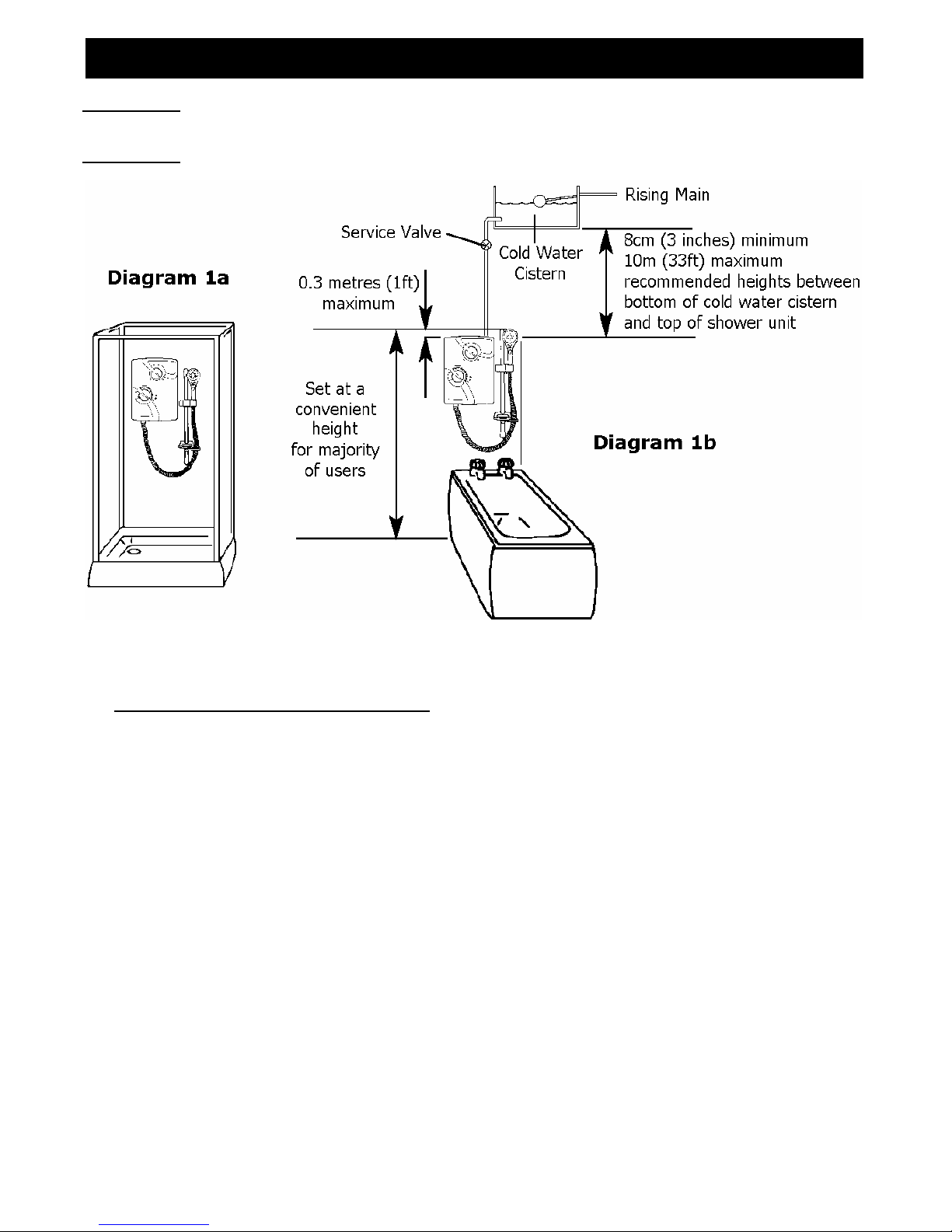
1. Position the riser rail at a convenient height for majority of users as detailed in Diagram 1a/b
and mark its position.
2. Position the heater so that the top of the unit is horizontal and level with, or a maximum of
0.3 metres (1ft) below the top of the riser rail. Choose a flat piece of wall to avoid the
possibility of distorting the backplate thus making the front cover a poor fit.
3. Adjust the position to get the most convenient arrangement taking the following into account.
• The heater must not be mounted in the direct spray from the handset.
• The handset must not be able to come into contact with used water in the cubicle, bath or
basin. If it can, even after the hose has been retained by the soap dish (see Diagram 10), a
vacuum breaker must be fitted (available from us).
4. Fix the riser rail with screws provided. The fixing holes at the base of the brackets will be
revealed by removing the plastic fronts. Assemble as shown in Diagram 10).
5. Decide the position of the electrical cable into the unit.
If top or bottom entry is chosen, cut away the walls in the backplate as shown in Diagram 3.
6. Decide the position of entry of the cold water pipe into the unit.
If top or bottom entry is chosen, carefully cut away the relevant walls of the backplate as shown
in Diagram 2
.
If bottom entry is chosen, refer to note 5 in the plumbing section.
HOW TO INSTALL YOUR CREDA SHOWER
Page 4
4
7. If you have not yet done so, remove the front cover assembly by undoing the retaining screws at
the top and bottom of the unit and lifting the cover off.
Your shower is provided with 3 fixing positions in the backplate (see Diagram 3).
The top-fixing hole is a “key-hole” slot (another key-hole is provided for alternate fixing), and
should be marked and drilled first.
Tighten top screw with head protruding about 10mm from the wall and hook the backplate over
the screw head. This allows for correct and accurate alignment of your shower before marking
and fixing the bottom position.
You may not wish to tighten up both screws at this stage as the holes are elongated to allow for
adjustment after other connections have taken place.
b. PLUMBING
WARNING: UNDER NO CIRCUMSTANCES SHOULD THIS UNIT BE CONNECTED TO THE
MAINS COLD WATER SUPPLY.
The heater must be connected to a cold water supply gravity fed from a static cold water cistern
with a minimum capacity of 114 litres (25 gallons).
There must be a minimum head of water of 8cm (3”) and a maximum head of 10m (33ft).
This shower is supplied with a filtered isolation valve which MUST BE fitted to the
inlet water supply (see note 2 below and Diagram 9b on page 11).
It is strongly advised to install the shower unit using an independent supply from the cold water
storage cistern. The shower would be totally unaffected by the other draw off points elsewhere in
the system and thus the pressure and temperature will remain more stable.
Therefore, the cold water supply should be taken directly from the cold water cistern.
Under no circumstances should any of the pipework supplying the shower unit rise above the level of
the bottom of the cold water cistern.
Before connecting the pipework to the shower ensure that the pipework is flushed out.
1. Unscrew the “Red Cap” and “Washer” from the shower
outlet pipe and discard them in a suitable manner.
These have been used to seal the shower during transit,
and are no longer required.
2. This shower is supplied with a filtered isolation valve
which MUST BE fitted between the cold water storage
cistern and the shower unit.
This will allow the unit to be serviced or exchanged
without having to turn off the cold water and draining
the cold water cistern.
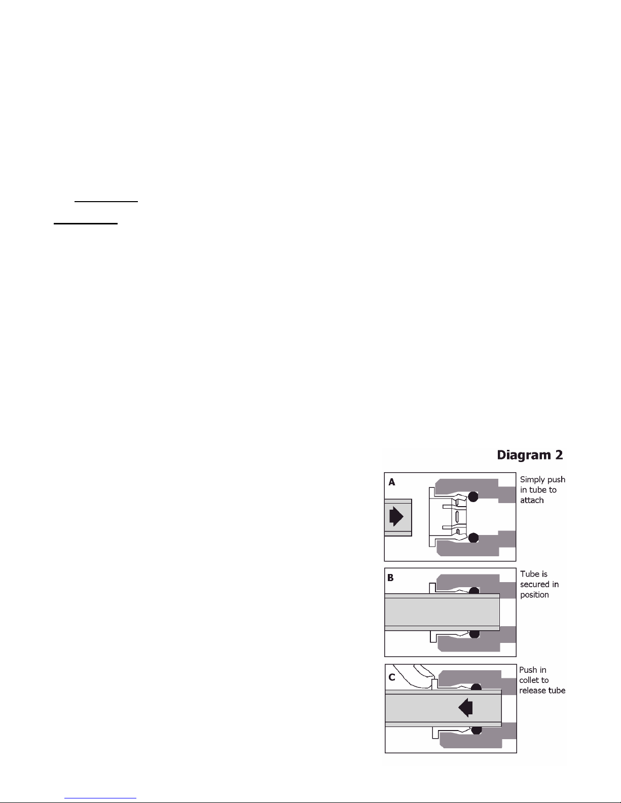
3. Ø15mm copper pipe should be used. Ensure all burrs
have been removed from the pipes before inserting
into the push fit inlet ports.
Diagram 2 illustrates the correct procedure for inserting
and removing the pipes from the inlet ports.
Take care to line up the inlet pipe correctly with the inlet
port to avoid straining the internal “O”-Ring seal.
DO NOT use solder fittings within 300mm of plastic
fittings.
4. To maintain the optimum performance, the pipe runs
should be kept as short as possible, using sweeping bends
rather than right angles or restrictive fittings.
Page 5

5
5. If bottom entry has been chosen, the inlet
port must be rotated through 180° into the
required position.
To do this, unscrew the side section from
the shower unit (see Diagram 3).
Rotate inlet connection ensuring that a snug
fit into the cradle is achieved, replace the
side section and tighten screw.
6. With isolating valve connected, flush the
pipe work through to remove any
particles etc, before making the final
connection to the shower.
Blockage in the water ways (particularly the
handset and filters) will prevent the shower
unit working properly.
Note: You may be charged for a service
call if it is due to incorrect installation.
7. The shower is designed to have an open
outlet and should only be used with
“Creda” recommended fittings.
Do not connect the handset until after the shower front cover and corner section are fitted.
WARNING: DO NOT FIT A TAP ON THE SHOWER OUTLET.
WARNING: TAKE CARE TO AVOID RESTRICTING THE OUTLET OF THE
PRESSURE RELIEF DEVICE (SEE DIAGRAM 6)
c) ELECTRICAL
WARNING: THIS SHOWER MUST BE EARTHED.
The electrical installation must be in accordance with the current
BS.7671 (IEE Wiring Regulations) and “Part P” of the Building
Regulations and/or local regulations
1. The shower unit is designed for a single phase AC electrical supply.
Please check the rating plate on the unit to see what details apply to your shower.
AS A GUIDE ONLY (* Only applies if external earth impedance is less than 0.35 Ohms)
Rating Cable Sizes
Fuse / MCB
Cable Length
6.0mm²
10.0mm²
40A Type B MCB
27m Max.
45m Max.
(Cat No. 24-555521)
8.6kW 230V
6.0mm²
10.0mm²
45A BS.1361 fuse
12m Max.*
21m Max.*
10.0mm² 50A Type B MCB 18
m Max.
(Cat No. 24-556021)
9.6kW 230V
6.0mm²
10.0mm²
45A BS.1361 fuse
12m Max.*
21m Max.*
Remember to upgrade the cable if it runs in thermal insulation in a loft, or for a longer distance.
2. A means for disconnection in all poles must be incorporated in the fixed wiring in accordance
with the wiring rules. We recommend a ceiling switch mounted in a convenient position.
3. Cut back cable as in Diagram 4. Connect cable to terminal block making sure that all the
retaining screws are VERY TIGHT and that no cable insulation is trapped under the screws.
WARNING: FAILURE TO COMPLY WITH THESE INSTRUCTIONS COULD RESULT IN
FAILURE OF THE TERMINAL BLOCK
Page 6

6
HOW TO MAINTAIN YOUR CREDA SHOWER
IMPORTANT WARNINGS!
THIS APPLIANCE IS NOT INTENDED FOR USE BY PERSONS (INCLUDING CHILDREN)
WITH REDUCED PHYSICAL, SENSORY OR MENTAL CAPABILITIES,
OR LACK OF EXPERIENCE AND KNOWLEDGE, UNLESS THEY HAVE BEEN GIVEN
SUPERVISION OR INSTRUCTION CONCERNING USE OF THE APPLIANCE
BY A PERSON RESPONSIBLE FOR THEIR SAFETY.
CHILDREN SHOULD BE SUPERVISED TO ENSURE THAT THEY
DO NOT PLAY WITH THE APPLIANCE.
4. A dual position cable clamp is provided.
For top cable entry use retaining bar in horizontal position supplied.
For bottom cable entry rotate retaining bar to the angled position.
d) FINAL INSTALLATION PROCEDURE AND COMMISSIONING
WARNING: DO NOT SWITCH ON THE ELECTRICITY SUPPLY UNTIL THE FOLLOWING
PROCEDURE HAS BEEN COMPLETED. FAILURE TO DO SO COULD CAUSE
THE PUMP TO RUN DRY AND INVALIDATE THE GUARANTEE
1. Fit the front cover back into position, ensuring that both the control knobs are correctly aligned
with the flow valve and power selector. Secure with top and bottom screws.
2. Fit hose and prime the shower first without the handset to flush out any remaining debris. To
prime the shower, ensure that the electricity supply is turned off. Turn control knob “B” fully
anticlockwise. Water should start to flow with motor switched off allowing all the air to be purged
out of the shower unit.
It may be necessary to lower the hose below the level of the shower whilst priming.
Stop water flow by turning control knob “B” fully clockwise. Attach handset, switch on electrical
supply and then operate the shower as on page 7 and check:a. That the water gets to a satisfactory temperature.
b. Water flow can be adjusted by control knob “B”.
c. Power selection operates in both positions, giving a change in water temperature.
d. Check again for leaks.
e. That the holes in the shower handset are not blocked.
f. That the motor turns off and water stops flowing in the “Stop” position.
3. DEMONSTRATE OPERATION TO USERS
It is recommended that the shower unit and hose etc. be cleaned using a soft cloth and that the use
of abrasive or solvent based cleaning fluid be avoided, especially on any plated finishes.
We recommend that before any cleaning, the isolating switch be turned off, thus avoiding
accidentally switching on the shower.
WARNING: YOU MUST REGULARLY INSPECT THE SHOWER HOSE FOR WEAR AND DAMAGE.
REPLACE IF NECESSARY, OR EVERY TWO YEARS, WITH AN APPROVED PART.
WARNING: IN ORDER TO MAINTAIN THE PERFORMANCE OF YOUR SHOWER,
YOU MUST CLEAN THE SHOWER HANDSET REGULARLY
All water contains particles of lime-scale, which build up in the shower handset and
unit reducing the performance.
It is therefore important to clean the shower handset by simply rubbing the rubber
nozzles, or soaking in proprietary lime-scale remover, rinsing thoroughly before use.
NOTE: After use it is normal for some water to drip from the shower handset for
a few moments. This inhibits scale build-up over prolonged use.
Page 7

7
IF WATER IS TOO COLD
Turn knob “B” clockwise in the direction
of the “red dots” a small amount and
continue turning clockwise until you get the
water temperature of your liking.
Wait 20 seconds after each adjustment
for the water temperature to stabilise.
The final adjustment may be anywhere on
the scale.
If after turning fully clockwise water is still
too cold, set shower pattern on shower
handset to outer or inner pattern only.
IF WATER IS TOO HOT
Turn knob “B” anti-clockwise in the
direction of the “blue dots” a small amount
and continue turning anti-clockwise until you
get the water temperature of your liking.
The final adjustment may be anywhere on the
scale.
If after turning fully anti-clockwise, water is
still too hot, adjust knob “A” to “ ” low
power setting and re-adjust as above.
Water flow will be reduced on this setting.
1. Ensure the electricity and water are turned on to the unit.
2. Your shower has 2 control knobs (see Diagram 5).
Knob “A” controls the 2 power settings.
The most popular is “high” indicated by “ ”.
There is also a “low” power option “ ” (see note 7).
Knob “B” starts and stops the unit and controls
the temperature of the water.
3. To start the shower turn knob “B” anti-clockwise.
The water will start flowing at around 15° knob rotation
(1 o’clock) and the motor will switch on at around 30°
(12 o’clock). The “power” light will illuminate at this stage.
4. Allow about 20 seconds for the temperature of the water to stabilise.
It is recommended that you test the water temperature with your hand before stepping under
the water spray during this period, even if the shower has just been used.
5. When you have finished showering, turn knob “B” fully clockwise to the “Stop”
position.
The motor will switch off and water will stop flowing.
The “POWER” light will go out.
6. Switch off the electricity at the ceiling switch or local isolator.
7. The “ ” low power setting of knob “A” reduces the power used by the shower giving a
cooler shower or the option of reduced water flow.
This option is mainly for summer usage, and if this is used then knob “B” must be
re-adjusted.
WARNING: DO NOT SWITCH THE SHOWER ON IF YOU SUSPECT IT OF BEING FROZEN.
WAIT UNTIL YOU ARE SURE IT HAS THAWED OUT.
WARNING: DO NOT OPERATE THE SHOWER IF WATER IS DISCHARGED FROM THE
PRESSURE RELIEF VALVE.
MAINTENANCE IS REQUIRED BEFORE THE SHOWER CAN BE USED.
WARNING: CONSIDERATION SHOULD BE GIVEN TO SUPERVISING THE YOUNG,
ELDERLY AND THE INFIRM WHILST THEY USE THIS SHOWER.
HOW TO USE YOUR CREDA SHOWER
Page 8

8
SELF HELP
If the shower is not working satisfactorily, make the following checks before calling out the installer.
Any one of these adjustments could restore the performance.
The shower cycles
from HOT to COLD
The shower temperature is set too hot causing the thermal cut-out (safety
device) to operate.
Turn knob “B” anti-clockwise (direction of the “blue dots”) to increase water
flow.
Slowly increase the water temperature by turning knob “B” clockwise in the
direction of the “red dots” until a comfortable showering temperature has been
reached.
You MUST WAIT approximately 20 seconds for each adjustment to affect the
water temperature.
“ ” low power setting may need to be selected.
Water too HOT Increase water flow by adjusting knob “B” anti-clockwise (direction of the “blue
dots”).
“ ” low power setting may need to be selected.
Increase pressure to water supply e.g. fully open service valve or stop cock.
Check hose is not kinked restricting the water flow.
Clean shower handset.
Water too COLD Check power is on (indicated by “power” light).
Decrease water flow by adjusting Knob “B” clockwise (direction of the “red
dots”).
“ ” high power setting may need to be selected.
Select inner or outer only handset spray pattern.
Pump operates
but no water is
delivered
Water starvation. Stop pump immediately by turning knob “B” fully clockwise to
the “Stop position”
.
Check the cold water cistern is full. Ensure water supply pipe is not blocked or
air-locked (see commissioning) with power to shower switched off.
Pump fails during
shower
Thermal trip inside motor has operated.
Wait for motor to cool down (approximately 30 minutes)
Spray pattern poor Clean the shower handset. Select an outer/inner spray pattern.
Water takes longer
to heat up
Thermal cut-out has operated after previous use (“overheat
” light is on)
(automatically resets when unit cools down)
“ ” high power setting may need to be selected.
Water goes cold
while using
shower
Thermal cut-out has operated (“overheat” light is on).
Wait for cut-out to reset.
Check power is on (indicated by “power” light).
Broken parts Please contact our spares department on 0870 9000 430 (UK Only) or
+385 1 842 8222 (ROI Only) or contact your local distributor
Please Note:- The fitting of Spare Parts must be supervised by a suitably qualified person.
Front Cover Cat No. 93590382 PRV Washer Cat No. 93795817
Tank-Base Assy Cat No. 93590307 Thermal Cut-Out 50/88°C Cat No. 93597836
Pump Assy Cat No. 93590313 Handset Cat.No. 93590736
Camshaft Assy Cat No. 93590312 Height Adjuster Cat No. 93593523
Tank Clip Cat No. 93590715
WHAT TO DO IF THINGS GO WRONG (1)
COMMON SPARE PARTS
Spare parts can be supplied against any Credit or Debit cards
RING: 0870 9000 420 (UK Only) / RING: +353 1 842 4833 (ROI Only)
Or contact your local distributor
Page 9

9
WHAT TO DO IF THINGS GO WRONG (2)
CREDA AFTER SALES SERVICE
PROFESSIONAL SERVICE
If the previous “Self Help” checks fail to restore the performance, you should seek professional help.
The person who installed the shower is probably the best one to investigate and correct it and is
certainly the person to contact if you have had a problem in the guarantee period.
The following additional checklist is provided for the benefit of the qualified service person.
WARNING:
SWITCH OFF THE ELECTRICITY AT THE LOCAL ISOLATOR
BEFORE REMOVING THE COVER TO MAKE CHECKS
Water too HOT Water flow restricted by a blockage in either the built-in pump filter or the
isolating valve filter.
Switch off the water supply at the isolation valve and fully isolate the
electricity supply, remove the appropriate filter, clean and replace (see
Diagrams 9a/b).
Water too COLD Check circuit through thermal cut-out.
Check circuit through microswitches on the pressure switch.
Check each element circuit.
Check tightness of electrical connections.
Pump fails to
operate
If the “power” light is illuminated, possible motor failure, replace if necessary.
If the “power” light remains off, check motor switch and replace if necessary.
Pump operates
but no water is
delivered
Faulty motor switch (short circuit). Replace motor switch.
Incorrect alignment of motor switch camdrive.
In off position, the alignment marks on the cam drive (see Diagram 6) should
be centered about motor switch actuator.
Water flow restricted by a blockage in either the built-in pump filter or the
isolating valve filter.
Switch off the water supply at the isolation valve and fully isolate the
electricity supply, remove the appropriate filter, clean and replace (see
Diagrams 9a/b).
Water discharges
from pressure
relief valve
Check for cause of high pressure and remove it.
Blockage on outlet e.g. blocked shower handset.
Replace the pressure relief disc (not covered by guarantee).
We offer a technical advisory service on the telephone to installers and other customers with
problems in the field.
RING 0870 9000 430 (UK Only) / RING +353 1 842 8222 (ROI Only)
or contact your local distributor
Some spare parts (see later section) can be supplied against Credit or Debit cards.
RING 0870 9000 420 (UK Only) / RING +353 1 842 4833 (ROI Only)
or contact your local distributor
Remember to quote the exact type of shower, as written on the front of the shower and on this
leaflet. The model and serial number are located on the bottom face of the shower.
Make a note of those numbers here, and be sure to quote them if you call for advice.
Model Number: _ _ _ _ _ _ _ _ _ _ _ / Serial Number: _ _ _ _ _ _ _ _ _ _ _
Note: You may be charged for a service call if you do not have the serial number.
Page 10

10
1. Water is heated instantaneously as it
flows over the heating elements in
the copper cylinder.
2. Your shower incorporates a pump
which boosts the incoming water
pressure to a level more suitable for
showering.
The motor is controlled by a switch
connected to knob “B”
3. The heaters are only switched on
when
sufficient water is flowing.
This will happen when the motor is
switched on, and is done automatically
with a switch which works on water
pressure.
4. The water is turned on and off by
a tap that is built into the shower.
5. If the water supply falls below a set limit, the pressure
switch will operate and switch off the power to the elements.
6. As a further safeguard, a thermal cut-out switches
the power off if the water temperature climbs above the
set limit and the “overheat” light will illuminate.
This cut-out, which gives an audible click, may also operate
due to residual heat when the shower is switched off.
It will reset itself if water is run through the shower for
10 to 20 seconds, and the “overheat” light will go out.
7. The pressure relief device is to safeguard against
abnormal pressure conditions, and provides a level of
appliance protection should an excessive build of
pressure occur within the shower.
Effect of Seasonal Incoming Water Temperature Changes
The required water temperature is achieved by adjusting the rate of water flow.
Diagram 8 shows the principle involved in relating temperature rise to flow rate.
The higher the water rate the lower the temperature and vice versa.
The temperature of the water supplied from the cold water storage cistern
can vary considerably throughout the year from 5 to 3
0°C.
This means that in the winter, flow rate will be less than in the summer to
ach
ieve the same outlet temperature.
In summer the “ ” low power setting may give adequate hot water.
In some winter conditions, it may be necessary to select the inner or outer spray pattern only of
your shower handset. This will ensure correct operation of the shower with a slightly lower flow rate.
HOW YOUR CREDA SHOWER WORKS
Page 11

11
Inlet Assembly Showing Filter Position
Removing the Filter from the Filtered Isolation Valve (Turn Water Off First)
FILTERS
ASSEMBLY OF ACCESSORIES
Page 12

12
:
APPLIED ENERGY PRODUCTS LIMITED, MORLEY WAY, PETERBOROUGH, PE2 9JJ
TEL: +44 (0) 1733 456789 / FAX: +44 (0) 1733 310606
Website: www.creda-showers.co.uk
We offer a technical advisory service on the telephone:
Ring: 0870 9000 430 (UK Only) / Ring: +385 1 842 8222 (ROI Only)
GUARANTEE AND CONTACT DETAILS
(A4) Leaflet No. 559-2334-21A
 Loading...