

Page 1
I
~
Cre
d
a
(
l
Coo
I
nstructio
Model
INSTALLATION INSTRUCTION
Installation i
provid
OPERATING AND MAINTENANCE INSTRUCTION
Fully explained on Page 4
s
ed on Pages 2 and 3
k
e
r
43961
s simple. Full instructions and a marking guide ar
D [600
.
.
H
n
s fo
o
o
mml
S
d
r
use
& 43963D[900mm]
S
·
e
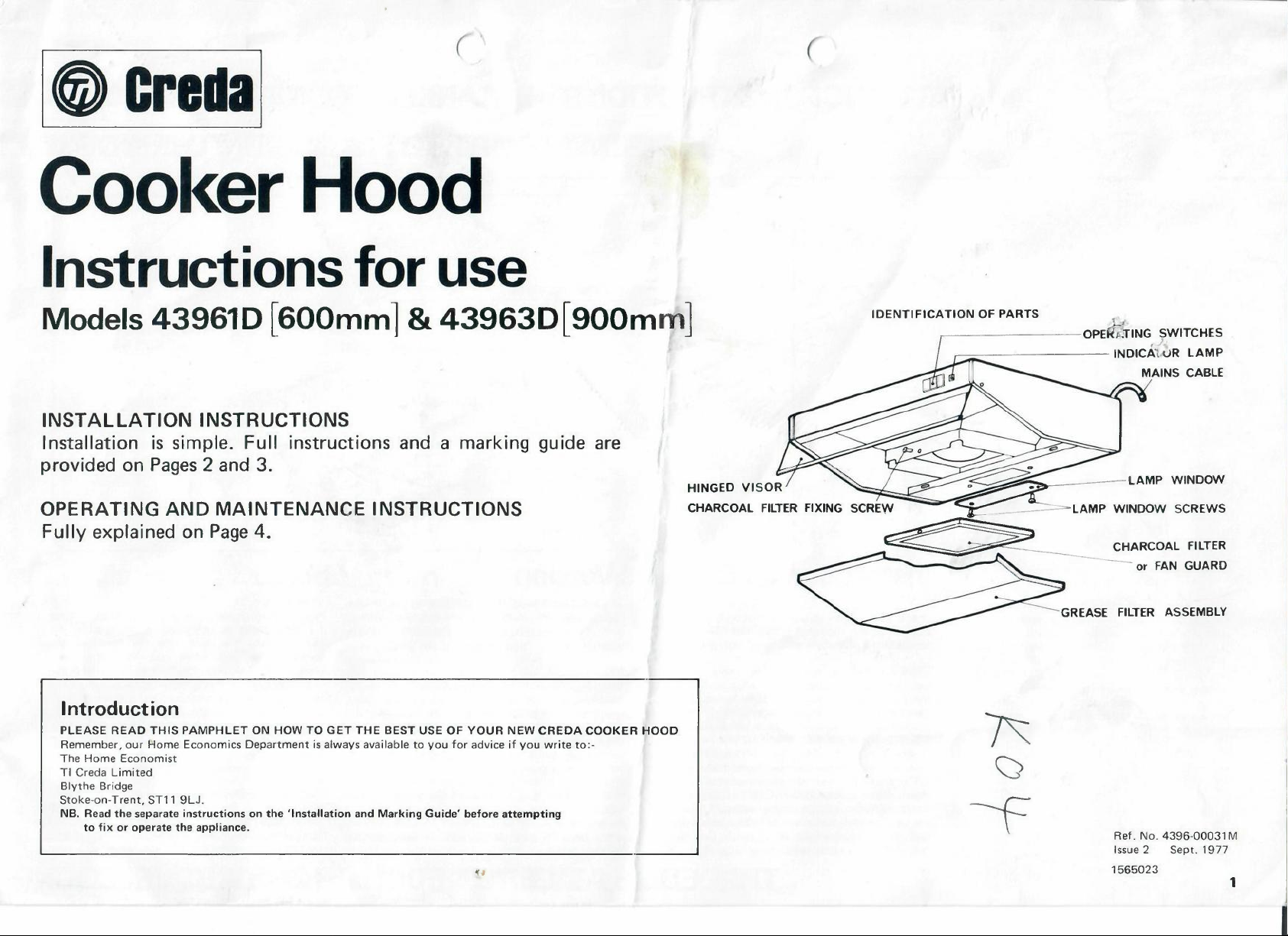
HINGED VISO
R
IDENTIFICATION OF PARTS
,--
------
-
p
-OPEl'<dlNG SWITCHE
- or FAN GUA
GREASE FILTER
'
.
,
INDICA1,uR LAM
SCREW
CHARCOAL FILTE
ASSEMBL
S
P
S
R
RD
Y
Introduction
PLEASE READ THIS PAMPHLET O
Remember, our Home Economics Department is always available to you for advice if you write to:
The Home Economis
TI Creda Limite
Blythe Bridg
Stoke-on-Trent, ST11 9LJ.
NB. Read the separat
to f
ix or operate the appliance.
t
d
e
e instructions on t
N HOW TO GET THE
he 'Installation and Marking Guide' before attemptin
BEST USE OF YOUR NEW CREDA COOKER HOOD
g
-
Ref. No. 4396-00031
Issue 2 Sept. 197
156502
3
M
7
1
Page 2
INSTA
LLATIO
N INST
RUCTIONS
&
MARl<IN
G GUID
E FO
R TH
E
l
~
C
I
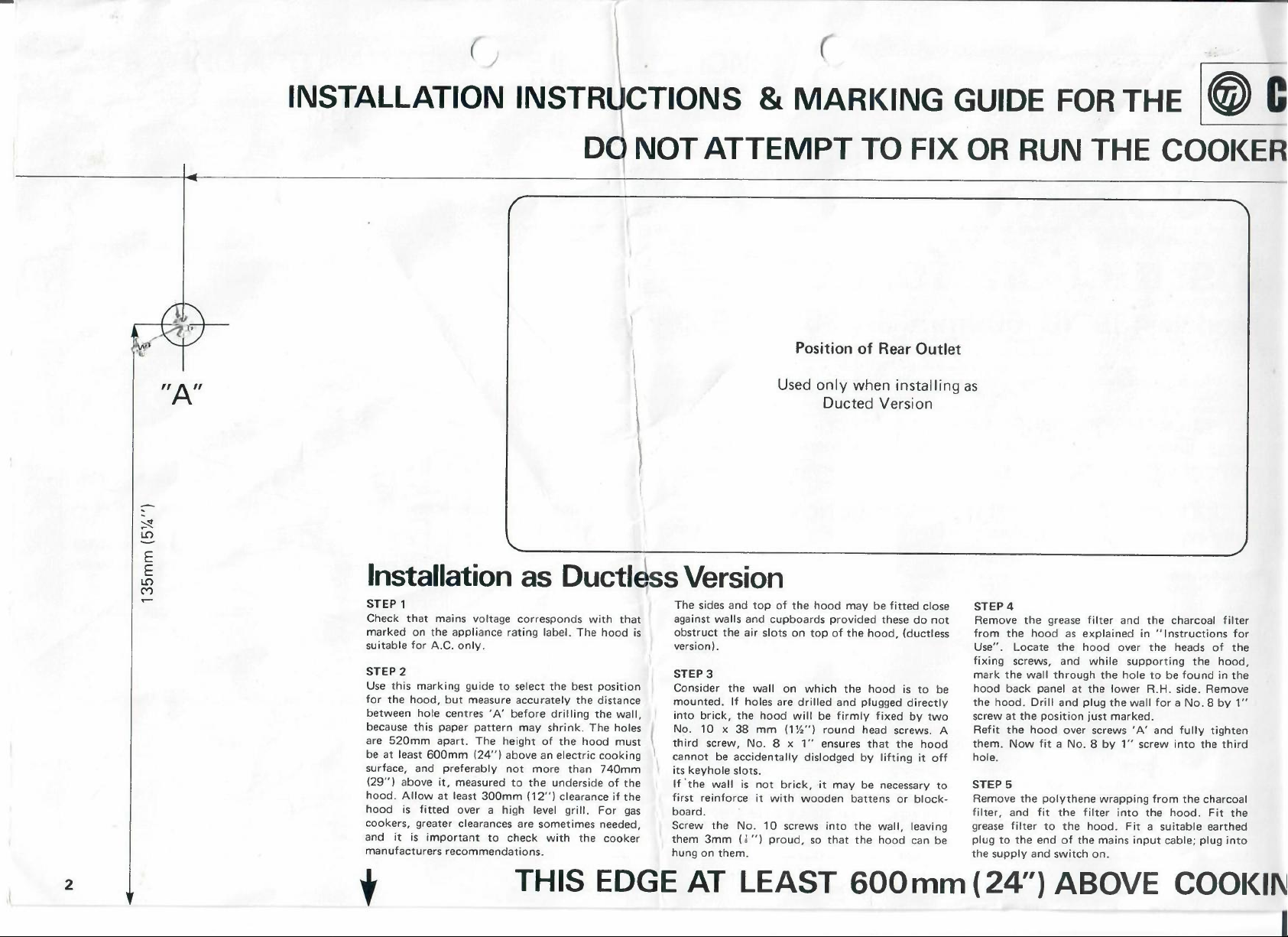
"A"
E
E
L
O
M
Dtj NO
T ATTEMP
Installation as Ductless Versio
STEP 1
Check that mains voltage corresponds with tha
marke
d on the appliance rating label. The hood i
suitable for A.C. only.
STEP2
Use this marking guide to select the best position
for the hood, but measure accurately the distance
between hole centres 'A' before drilling the wall,
because this paper pattern may shrink. The hole
are 520mm apart. The height of the hood mus
b
e at least 600mm (24"
surface, and preferably not more than 740m
(29") above it, measured to th
h
ood. Allow at least 300mm (12") clearance if th
hood is fitted over a high level grill. For gas
cookers, greater clearances are sometimes needed,
and it is important to check with the cooker
manufacturers recommendations.
) above an electric cookin
e underside of the
T
he sides and top of the hood may be fitted clos
t
against walls a
s
obstruct th
version)
STE
Consider the wall on which the hood is t
mounted. If holes are drilled and plugge
into brick, the hood will
s
No. 10 x 38 mm (1½") round head screws. A
t \
third screw, No. 8 x 1" ensures that the hoo
g
cannot be accidentally dislodged by lifting it off
m
its keyhole slots.
If "the wall is not brick, -it may be necessary to
e
first reinforce it with wooden battens or black
board.
Screw the No. 10 screws into the wall, leaving
them 3mm ( l ") proud, so that the hood can be
hung on them
e air slots
.
P 3
.
T TO FI
Position of Rear Outle
Used only when installing as
Ducted Versio
n
nd cupboards provided these do no
on top of the hood, (ductle
be firmly fixed by tw
n
o b
d directl
X OR RU
t
e
STEP4
t
Remove the grease filter and the charcoal filte
ss
from the hood as explained in "Instructions for
Use". Locate th
fixing screws, and while supporting the hood
mark the wall through the hole to be found in th
e
hoo
y
o
d
-
d back panel at th
the hood. Drill and plug the wall for a No. 8 by 1
screw at th
Refit the hood over screws 'A' and ful
them. Now fit a No. 8 by 1" screw into the thir
hole.
STEP 5
Remove the polythene wrapping from the charcoal
filter, a
grease filter to th
plug to the e
the supply and switch on.
N TH
e hood over th
e position just marked.
nd fit the filter into the hood. Fit th
e hood. Fit a suitable earthed
nd of the mains input cable; plug int
E COOl<E
e heads of the
e lower R.H. side. Remov
ly tighte
R
r
,
e
e
"
n
d
e
o
2
t
THI
S EDGE AT LEAS
T 600m
m
(24")
ABOVE COOl(I
N
Page 3

~
I
OO
C
OOKE
R HOOD MODELS 43961D(600
D WITHOU
T
READIN
G THES
mm
E INSTRUCTIONS
)
!
&
43963D(900
AA= 520m
m
m
m
)
RECTANGULAR-TO-ROUN
CONVERTER FOR
-
0
0
0
I
.•...
0
Q
)
C
:
OUTLE
T
D
::i
Q
)
•..
.
+-'
C
:
Q
)
u
OUTLET ADAPTOR
I
nstallation as Ducted Version
STEP 1
Most o
f the preceding instructions for mountin
the hood on the wall ar
read first
STEP2
Use this markin
of the outlet if it is to be ducted straight out
through the wall behind the hood.
Alternatively the outlet adaptor may be turn
through 90 degrees so that the airflow is throu
the top o
ducting along the wall - usually hidden b
cupboards - to an outside wall
STEP3
The top/rear outlet cover plate is removed from
the hood, and replaced by the outlet adaptor. Th
outlet slots in the top of th
.
f the hood, whence it is conveyed by
e applicabl
g guide to select the best positio
e a
nd should be
.
e hood, which normally
return filter
g
be blanke
found in the carton, is fixed carefully i
after peeling off the paper backing from the self
adhesive strips on it.
The charcoal filter is tak
n
empti
all for the ducted version. The empty filter-fram
is replaced in the hood to serve as a safety guard
ed
near the fan blades
gh
If the charcoal is left in, there will be insufficient
air-flow through the ducting
y
The washable grease filter is le
STEP 4 DUCTING
If the hood is ducted rear-wards through the wall
the hole should
e
into the cavity of the wall. Any external grill
should not reduce the total cross-sectional area of
EXHAUST GRILL COVE
ed air into the kitchen, must of cours
d off. An exhaust grill cover, t
en from th
ed of its charcoal, which is not required a
.
.
ft in place
be lined so that steam is not blow
o b
n place
e hood an
.
R
(
I
e
outlet below 19 squar
e
TOP DUCTED HOOD
,
T
he ducting may be of simple box form, built
-
site.
Alternative
d
a "square-to-round" converter, available from:-
t
Spares Department, Creda Electric Ltd., P.O. Bo
e
4, Blyth
The ducting is then even more simple, consisting
of a length of 5" bore flexible, lightweight hose.
We recommend "Glasflex", which is flame-resistan
fibreglass cloth on a spiral wire framework
It is not on
"Concertina" to feed it through holes in the wall-
,
cupboards. Ensure that all direction changes are
smooth bends, and that the cross-sectional area of
n
e
ducting an
sq.in. (123 sq.cu.l, and the total length of duc
ly the outlet adaptor can be fitted with
e Bridge, Stoke-on-Trent, Staffs. ST
ly very easy to bend, but will also
d outlet grill
e inches.
S
e does not fall below 19
11 9LJ.
.
"A"
should not exce
"Glasflex" hose, 5" diameter, Code 0680 is avail-
able from distributors throughout the country.
on
In case of difficulty, contact- Compoflex Co. Ltd
at Oldham (Tel. 04577-5511) or Bicester (Tel
Bicester 42043)
Alternatively, flexible steel tube or plastic tube o
x
the appropriate size can be used. Care should b
taken as a smaller diameter tube c
performance of th
t
t
ed about 3 metres.
.
e hood.
an reduce th
.,
.
f
e
e
· SURFAC
E OR 300m
m (12") ABOV
E EY
E LEVE
L GRIL
L
t
3
Page 4

OPERATING AN
WARNING. THIS APPLIANCE MUST BE EARTHED.
IMPORTANT. The wires in this mains lead are coloured i
accordance with the following code:-
Green-and-Yellow: Eart
Blue
:
Brown
:
As the colours of the wires in the mains lead o
may not correspond with the colour
terminals in your plug, proc
The wire which is coloured green-and-yellow must be c
to the terminal in the plug which is marked with the letter E or
by the earth symbol
The wire which is coloured blue must be connected to the
terminal which,-*:narked with the letter N or coloured black.
T
he wire which is coloured brown must be connected to th
terminal which is marked with the letter L o
If a
1
3
amp (BS
or if any other type of plug is used a 5 amp fuse must be fitt
either in the plug or adaptor or a
REMOVING AND REPLACING THE GREASE FILTER
ASSEMBLY
Grasp the Filter Assemb
shown and s
This will disengage the locating
pins at the back of the assembly.
The back of the Filter will
become free so that it c
moved downwards
When the Filter back is free,
move the Assembly away from
you to disengage the front edge.
Replacement is done in the reverse sequence
REMOVING AND REPLACING THE GREASE FILTE
ELEMENT
1
.
Pull the centre rod of the Filter Retainer at the position
and in the direction indicated by the arrows.
.
lide it towards you
1363
.
h
Neutra
l
Liv
e
eed as follows
!
-
or colour
)
plug is used,
ly as
an b
D MAINTENA.4CE INST1R
ed markings identifying the
ed green or green-and-yellow
a 3 amp fuse must be fitted,
t the distribution board
~
.
f this applianc
:
onnecte
r coloured red.
1
• ,{!J
~
e
~
~
'=--
.
-
2
3
~
I .•
R
n
e
d
.
e
ed
.
I
I
s
UCTION
2
. The Locking Projections will disenga
Frame. Remove the Filter Retainer and thereafter th
Filter Element.
3
.
Replacement is
The Filter Element traps grease from the cooking fumes
Remove the Element AT LEAST ONCE A MONTH or mor
often if you do a lot of frying. Wash it in hot water, just
bearable to the hand and containing a little detergent o
washing up liquid. Gently squeeze out excess water and allow t
dry. Replace when dry
After approximately 2
ment. New Elements can be obtained from your stockist or
direct from Creda Electric Limited
REMEMBER cooking grease is inflammable. A frequency of
cleaning as recommended abov
precaution. Furthermore, a congested Element will reduce the
efficiency of the Hood an~ allow contamination o
Filter.
REMOVING AND REPLAblNG THE CHARCOA
Models 43961 D (600mm) and 439630 (900mm)
CHARCOAL FILTER FIXING SCRE
1. Unplug the Hood from the electric supply.
2
. Remove the Charcoal ~i1ter Fixing Screw.
3
.
Place the thumbs in t~e Thumb Apertures a
direction of arrows. The Filter will become free at th
front of the Hood enabling it to be removed.
4
. Replac
5
.
CARE OF THE CHARCOAL tiiLTER
Models 43961 D (600mm) and 139630 (
AFTER MANY MONTHS - cetween six and eightee
on use - the charcoal filter- wi
removing cooking smells, and it will be time to rechar
fresh material, which can be purchased from the dealer wh
supplied the appliance (or in tase of need, direct
will only be necessary to remove the charcoal filter, empty it o
the used materia
poured in
e in the revers
NOTE that the Charcoal Filter is contained in a polythen
bag for transport only. Remove th
using the filter
.
1
done
in the reverse sequence.
.
0
washe
s
the Element will need replace-
.
e is essential as a normal safety
I
W
e
spquence.
.
900mm
ll become le
l and re-fill it, shaking the powder down as Lt is
S
ge from the Filte
f the Charcoa
L FILTE
e bag before fitting and
l
ss effectiv
R
nd press in
n depending
e i
ge it with
from us). I
r
e
.
e
r
o
l
e
e
n
o
t
f
The grade and quality o
the efficien
only genuine Creda refills from your stockist or direct fro
TI Creda Limited. Before removing the Charcoal Filter unplu
t
he Cooker Hood from the electric supply
REPLACING THE LIGHT BUL
Remove the Lamp Window Screws. Move the Lamp Window
away from yo
remove. The normal domestic 40w. lamp is located in the
exposed aperture
CHECKING THE OPERATION OF THE COOKE
The instruction for use is simply, switch on. The switch marke
"light" controls a convenient light within the hood which ca
be used whether or not the fan is in operation
Press the switch marked "Fan 2" when a hea
of cooking fumes must be filtered. This gives full speed fan
rotation. For normal cooking, press the switch marked "Fan 1 "
This gives a fan rotation of reduced speed.
When the f
turbulanc
The Hood is fitted with a transparent plastic Visor the purpos
of which is to enlarge the steam and cooking fumes catchmen
area. When the Hood is in operation adjust the Visor into the
hinged forwar
Visor fully back so that it is conveniently out o
Whenever the Fan is in operation the indicator lamp wil
illuminate
Use the Creda Ho
too for jobs like peeling onions (preferably under, or very nea
to the Hood). Remember to switch on the Cooker Hood before
you start to cook.
Try to avoid cross-draughts, which will blow fumes away fro
the intake. Also remember not to leave gases flaring or ho
plates switched on, after yo
CARE OF THE COOKER HOOD PAINTED SURFACE
The hard, white surface is made to be wiped over as often a
you wish. Please use a damp cloth, and avoid abrasive cleaners,
frequent gentle attention is not only better than occasional har
rubbing but your new possession will always be spick and span.
DUCTE
If the hood is connected to a duct, the steam and cooking
smells will be carrie
b
een removed by the washable filter. This filter should be
washed every month
Charcoal filtration is unnecessa
obtain the full rate of air-flow through th
filter should be taken out, emptied of its charcoal granules, and
the empty filter-frame replaced in th
guard for the fan-blades.
Remember to replace the central fixing screw and washer
cy of your Cooker Hood. For the best results use
u and downwards when it will become free t
an is running a certain amount of noise caused by air
e is inevitable.
d position. When the Hood is not i
.
D HOODS
f the Activat
.
od whenever cooking smells are likely, use i
u have removed the pans.
d out of the kitchen, after the greas
.
ed Charcoal used will affec
.
B
R HOO
D
.
vy concentration
n use hinge the
f the way.
S
ry for ducted hoods, and to
e h
ood, the Charcoal
e hood to act as a safety
m
m
d
e has
t
g
o
d
n
.
e
t
l
t
r
t
s
.
4
 Loading...