


CREATOR Electronics
DVI Matrix Switcher
DVI Matrix Switcher
User Manual
Please read this manual carefully before using this product
DVI Matrix Switcher
A Version CR-DVI0808-A-01
2006 July

Notes:
This DVI Matrix Switchers User Manual takes example of the Matrix model
DVI0808-A. It can be used as user’s manual of other RGB matrix switcher
models.
This manual is only an instruction for operators, not for any maintenance usage.
Any changes of functions and parameters since then will be informed separately.
Please refer to the dealers for the latest details.
This manual is copyright CREATOR Corporation (China). All rights reserved. No
part of this publication may be copied or reproduced without the prior written
consent of CREATOR Corporation (China).
All product function is valid till 2006-6-30

DVI Matrix switcher user manualCR-DVI0808-A-01 CREATOR
!
Safety O
p
eration Guide
In order to guarantee the reliable operation of the equipments and safety of the staff,please
abide by the following proceeding in installation, using and maintenance:
⑴
The system must be earthed properly. Please do not use two blades plugs and ensure the alternating
power supply ranged from 100v to 240v and from 50Hz to 60Hz.
⑵
Do not put the switcher in a place of too hot or too cold.
⑶
As the power generating heat when running, the working environment should be maintained
fine ventilation, in case of damage caused by overheat.
⑷
Please cut off the general power switch in humid weather or left unused for long time.
⑸
Before following operation, ensure that the alternating current wire is pull out of the power
supply:
A. Take off or reship any components of the equipment.
B. Take off or rejoin any pin or other link of the equipment.
⑹
As to non-professional or without permission, please DO NOT try to open the casing of the
equipment, DO NOT repair it on your own, in case of accident or increasing the damage of the
equipment.
⑺
DO NOT splash any chemistry substance or liquid in the equipment or around.
ii

DVI Matrix switcher user manualCR-DVI0808-A-01 CREATOR
Contents
1. Introduction.........................................................................................................................1
1.1 About DVI Matrix Switcher System.............................................................................................1
1.2 DVI Matrix Switcher Models........................................................................................................1
2. DVI Packing of the Product..............................................................................................2
3. DVI Installation....................................................................................................................2
4. Front View and Rear View of the Product .....................................................................3
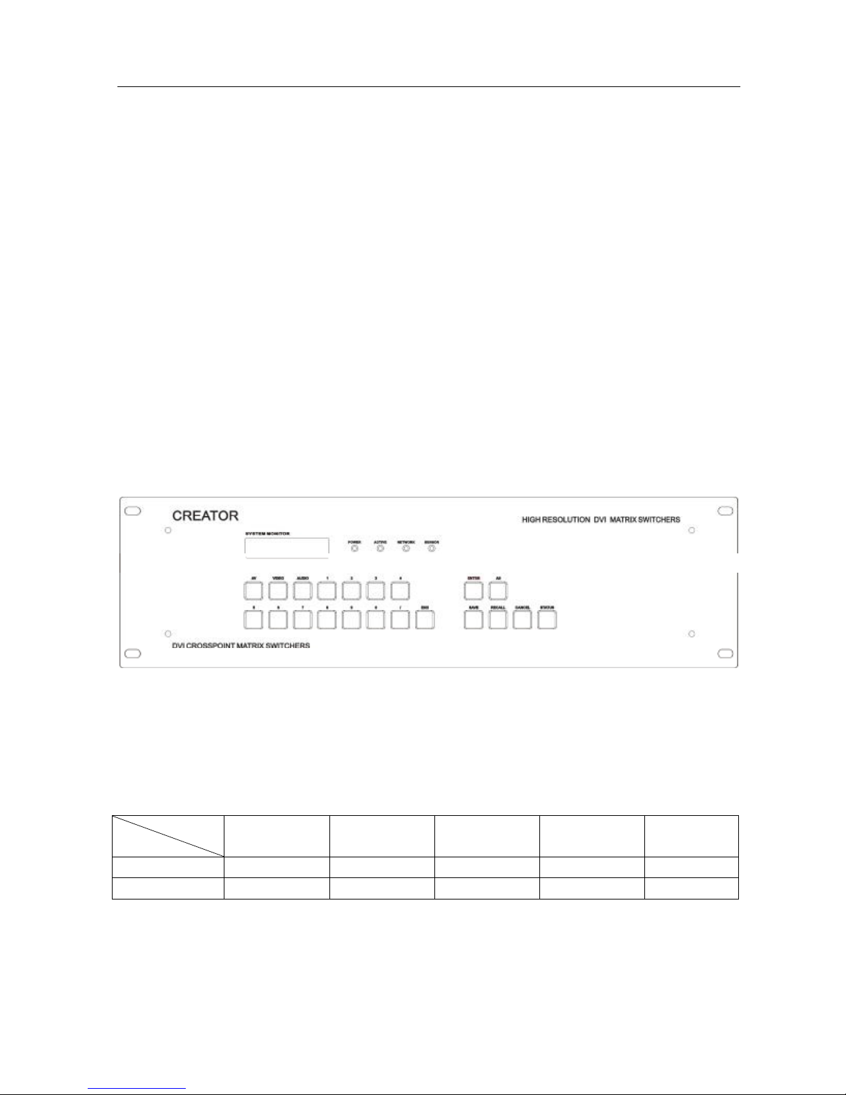
4.1 Front view of DVI0808-A...............................................................................................................3
4.2 Rear view of DVI0808-A................................................................................................................3
5. External Connection..........................................................................................................3
5.1 Introduction of the Input and Output Connectors......................................................................3
5.2 Connection of RS-232 Communication Port................................................................................4
5.2.1 Connection with Control System.........................................................................................................4
5.2.2 Connection with Computer...................................................................................................................4
5.2.3 Using Of Ethernet Adapter ...................................................................................................................4
5.3 How to Connect with the Input and Output Terminals..............................................................7
6. Operation of the Control Panel......................................................................................11
6.1 Front Panel Description................................................................................................................11
6.2 Command Format of the Switching Operation.........................................................................12
6.3 Examples of Operation.................................................................................................................13
7. Usage of the Remote Controller (Optional Accessory) .........................................14
8. Operation of the Switcher Application.........................................................................15
8.1 Introduction of SWITCHER 2.0.................................................................................................15
8.1.1 About the Application ..........................................................................................................................15
8.1.2 Starting the Application .......................................................................................................................15
8.2 Real function illumination...........................................................................................................15
8.2.1 Interface Description:..........................................................................................................................16
8.2.2 Description of SYSTEM Tab...............................................................................................................16
8.2.3 Description of KEYBOARD Tab.........................................................................................................16
8.2.4 Auto switching function.......................................................................................................................17
8.2.5 Custom Code .......................................................................................................................................18
8.2.6 Code Group..........................................................................................................................................18
8.2.7 Description of Send/receive Code List Tab......................................................................................19
9. Communication Protocol and Command Codes.......................................................21
10. DVI Technical Specifications......................................................................................25
iii

DVI Matrix switcher user manualCR-DVI0808-A-01 CREATOR
11. Troubleshooting & Maintenance................................................................................27
iv
DVI Matrix switcher user manualCR-DVI0808-A-01 CREATOR
1. Introduction
1.1 About DVI Matrix Switcher System
DVI series Matrix switcher is a high-performance professional computer and audio signal switcher
that can be used for cross switching of multi computer and audio signal. Independent DVI
component and balance/unbalance I/O terminals make each component signal transmit and
switch separately; this design can reduce attenuation of signal transmission to minimum and
output the image and audio signal in high-fidelity quality.
DVI series switcher mostly apply in broadcasting TV engineering, multi-media meeting room, big
screen display engineering, television education, command control center or other fields. It
provides power-fail locale protection function, LCD displaying, A/V timing or separating switching
function. It also has a adaptable compensation to extend the input distance to 36 meters. With
RS232 interface, it can be worked with PC, remote control system and any other far-end control
system devices. The user manual takes DVI0808-A as the example, other models can take
reference from it too.
1-1 DVI0808-A switcher
1.2 DVI Matrix Switcher Models
According to different situation and users, the DVI series can be classified into the following models:
Specification
Model
DVI0808-A 8 8 8 8
DVI1616-A 16 16 16 16
Video Inputs Video Outputs Audio Inputs Audio Outputs
1
RS232
√
√
DVI Matrix switcher user manualCR-DVI0808-A-01 CREATOR
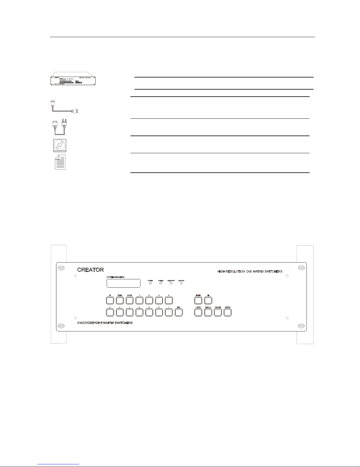
2. DVI Packing of the Product
DVI Matrix Switcher
RS-232 Communication Cord
Power Supply Cord
CD with Application SWITCHER to DVI
User Manual and Quality Guarantee
3. DVI Installation
DVI matrix switchers adopt metal shell and can be stacked with other device. Moreover, they are
rack-mountable enclosure and can be installed in the standard 19 inches case.
2
DVI Matrix switcher user manualCR-DVI0808-A-01 CREATOR
4. Front View and Rear View of the Product
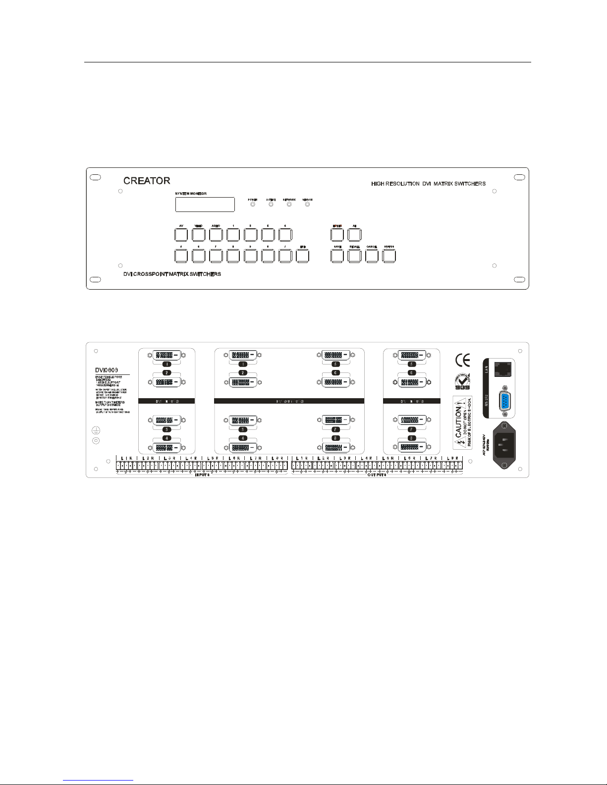
4.1 Front view of DVI0808-A
4.2 Rear view of DVI0808-A
5. External Connection
5.1 Introduction of the Input and Output Connectors
According to different type of matrix, computer signal I/O interface are made up of 8-channel
BNC ports and DVI-D female ports respectively. audio signal I/O terminals are make
up of 8-channel BNC ports and DVI-D female ports respectively. Please refer to shell
3
DVI Matrix switcher user manualCR-DVI0808-A-01 CREATOR
silk-screen figure about other types of interface.
5.2 Connection of RS-232 Communication Port
Except the front control panel, the DVI matrix switcher can be control by far-end control
system(Such as PC,CRESTRON control system, AMX control system, CREATOR control system)
or through the Ethernet control via the RS-232 communication port.
5.2.1 Connection with Control System
With the RS-232 port, the RGB matrix switchers can be control by several kinds of control
systems.
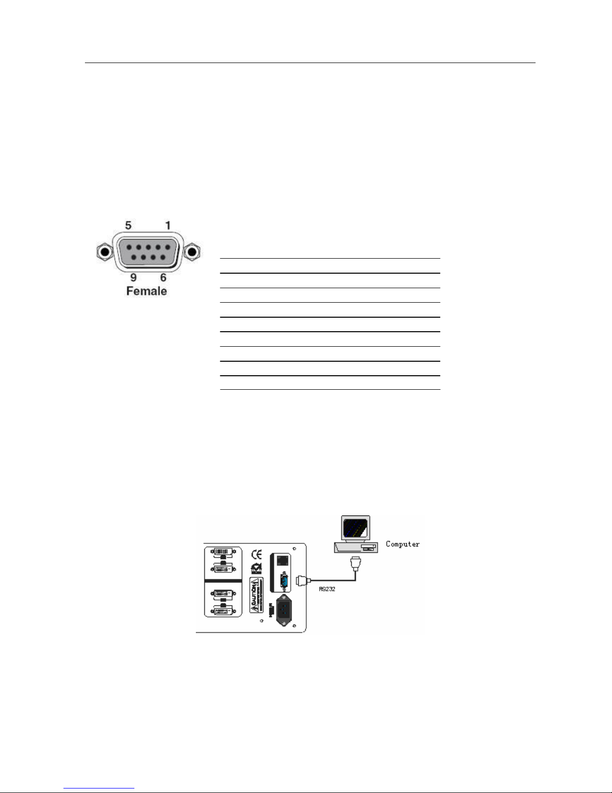
This RS-232 communication port is a female 9-pin D connector. The
definition of its pins is as the table below.
No. Pin Function
1 N/u Unused
2 Tx Transmit
3 Rx Receive
4 N/u Unused
5 Gnd Ground
6 N/u Unused
7 N/u Unused
8 N/u Unused
9 N/u Unused
F 5-1 9HDF
5.2.2 Connection with Computer
When the switcher connects to the COM1 or COM2 of the computer with control software, users
can control it by that computer.
To control the switcher, users may use the application SWITCHER 2.0 in the supplied CD or
develop their own control software. Please refer the details in Communication Protocol and
Command Codes
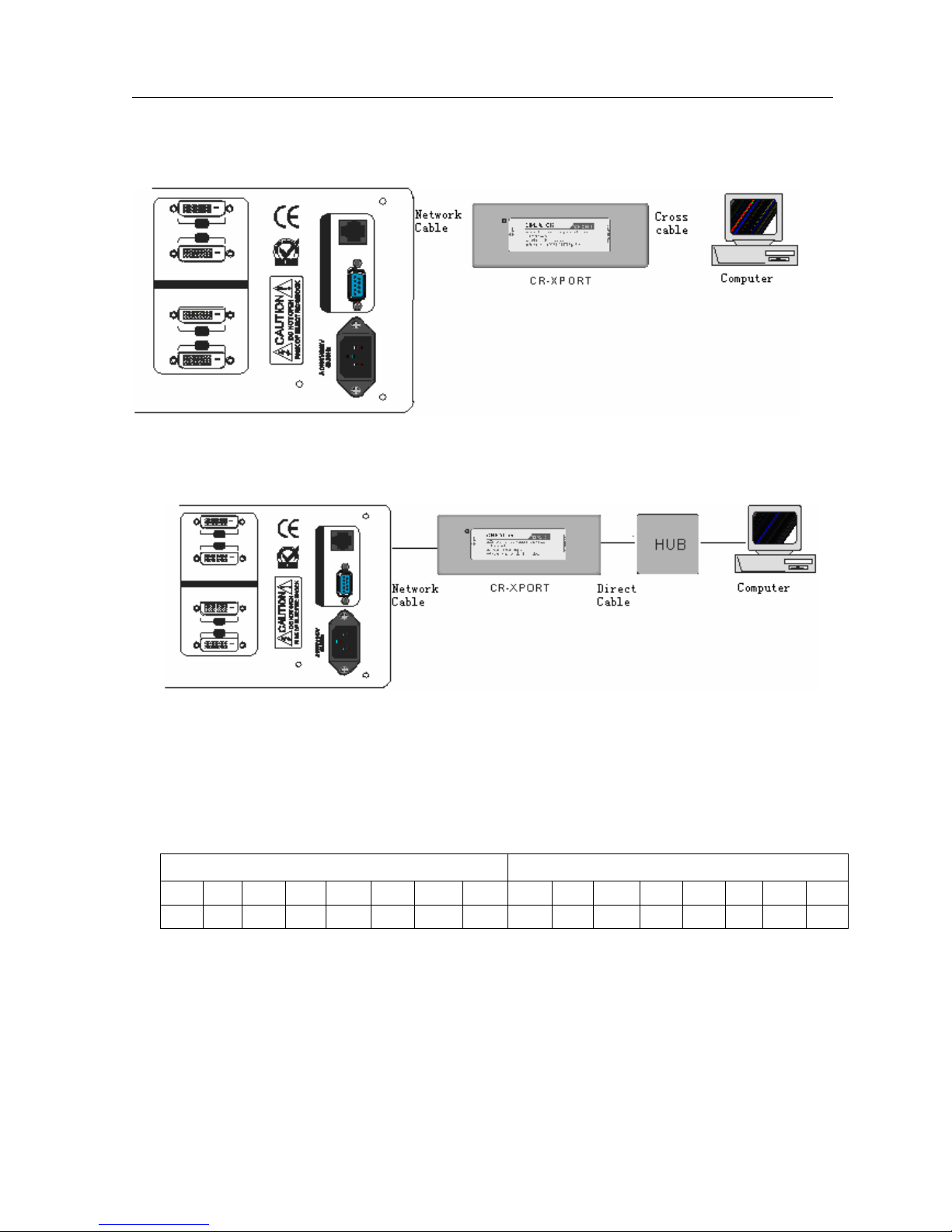
5.2.3 Using Of Ethernet Adapter
5.2.3.1 Connection Of Hardware:
There are two ways to connect the RGB matrix switcher and the hardware of Ethernet Adapter.
F 5-2 DVI connecting to computer
4
DVI Matrix switcher user manualCR-DVI0808-A-01 CREATOR
A. Cross connection
The RGB matrix switchers connect to the LAN port of Ethernet Adapter XPORT via 6-bit network connections
directly. The Ethernet Adapter connects to the Ethernet port of the computer via CAT-5 across cable directly.
B. The RGB matrix switchers connect to the LAN port of Ethernet Adapter XPORT via 6-bit network
connections directly. The Ethernet Adapter connects to the Ethernet port of the computer via Hub with
CAT-5 straight cable.
5.2.3.2 Declaring of across cable and straight cable:
We use CAT-5 as wire in this system, connecting network equipment via installing RJ-45 connection in
both side of CAT-5. The connection standard of twisted-pair is not set casually, it must ensure the
symmetry of the cable connector, so the interference of those cables can be counteract each other.
Super CAT-5 wire usually contains 4-pairs thin wire wring together, distinguishing by different colors.
There are two ways to connect the twisted-pair: Standard EIA/TIA 568B and Standard EIA/TIA 568A.
T568A order T568B order
1 2 3 4 5 6 7 8 1 2 3 4 5 6 7 8
GW G OW B BW O GrW Gr OW O GW B BW G GrW Gr
Straight cable: According to Standard T568B in both side.
Across cable: According to Standard T568A in one side, and Standard T568B in another.
5.2.3.3 Configure Declaring Of Ethernet Control Adapter:
6-bit cable facture:
6-bit cable is used to connect RGB matrix switcher and Ethernet adapter. Connecting crystal-head
of two ports just as 1-1, 2-2, 3-3 … 6-6.
5

DVI Matrix switcher user manualCR-DVI0808-A-01 CREATOR
A. Modify the IP Address of Ethernet control adapter.
Suppose the old IP address of Ethernet control adapter is 192.168.0.223
Step1: AS the graph shows, input “telnet 192.168.0.223 9999, Enter”, then display reminding
information. Input “Enter” again, turn into the main setup interface.
Step 2: Main control interface as follow, reminding you to choose the options you want to modify.
Step 3: We choose 0 Server 1 channel 1 to setup here. Input “0, enter”.
Step 4: Now the system would display the head of the IP Address 192.168.0.223, “192”, if you
want to change it for “193”, input the number”193, Enter”, finish the modification of head. Now the
system would display the second segment of the IP Address (193), (168); you can modify them one
after another. Finish all the modification after input “Enter” for four times. Now the system remind
6

DVI Matrix switcher user manualCR-DVI0808-A-01 CREATOR
you that whether to change the gateway.
A. Modify the gateway of Ethernet control adapter.
Modifying segments one after another, input “Enter” after each segment. As follows,”192.168.0.1 ”
B. Modify the net mask of Ethernet control adapter
Choose default 0 will be OK.
C. Modify the telnet config password of Ethernet control adapter
Needless to change, input “Enter” to return the main configure menu.
D. SAVE(Y/N) configure of Ethernet control adapter.
In the main configure menu, input “9, Enter”, Save the settings and quit.
In the main configure menu, input “8, Enter”, Quit and not save.
E. Please refer to “Ethernet control adapter Using Manual” for the details.
5.3 How to Connect with the Input and Output Terminals
The DVI matrix switchers may take DVD players, computers, graphic workstations and digital
showing platform as their input signal source, and projectors, video recorders, displayers and
7

DVI Matrix switcher user manualCR-DVI0808-A-01 CREATOR
8
17
24
amplifiers as their output signal destinations according to different situation.
DVI-D Dual Link:
1
9
F5—3 DVI-D Dual Link port
DVI-D pin function
PIN function PIN function
1
2
3
4
5
6 DDC Clock 18 T.M.D.S. Data 0+
7 DDC Data 19 T.M.D.S. Data 0/5 Shield
T.M.D.S.Data2-
T.M.D.S.Data2+
T.M.D.S. Data 2/4 Shield
T.M.D.S. Data 4-
T.M.D.S. Data 4+
13 T.M.D.S.Data3+
14 +5V Power
15 Ground (for +5V)
16 Hot Plug Detect
17
T.M.D.S. Data 0-
8 No Connect 20 T.M.D.S.Data5-
9
10 T.M.D.S.Data1+ 22 T.M.D.S. Clock Shield
11 T.M.D.S.Data1/3 Shield 23 T.M.D. S. Clock +
12
Audio signal connection:
“AUDIO INPUT”, “AUDIO OUTPUTS” audio network interface in RGB matrix switchers can be
connected to the audio signal and amplify of the DVD player.
Audio connection is little complicated than video. It has two kinds of connection: balanced and
unbalanced.
The balanced connection transmits a pair of balanced signals with two signal cords. Because
T.M.D.S.Data1-
T.M.D.S.Data3-
21
24
8
T.M.D.S.Data5+
T.M.D.S .Clock-

DVI Matrix switcher user manualCR-DVI0808-A-01 CREATOR
Tip
Balanced Output
Tip
Sleeves
interferences will have the same intensity and the opposite phases on the two signal cords, it will be
counteracted in the end. For the low frequency extent of the audio signal, it would be easily interfered
under long distance transmission. Therefore, as an anti-interference connection, it is mostly used in
audio connection of special device.
The unbalanced connection transmits signals only with a signal cord. Without counteraction, it can be
interfered more easily. Accordingly, it is adopted for household appliance or some cases with low
technical demand.
Take the audio signal line for example: 1.Unbalanced: pin “G” connect to SLEEVE, pin “+” connect to
TIP, pin “–” connect to pin “G”; 2.Balanced: pin “G” connect to SLEEVE, pin “–” connect to RING, pin “+”
connect to TIP. As shown in the F 5-3:
Sleeve
Sleeve
Tip
Tip
Sleeves
Tip
Tip
Ring
Sleeves
Tip
Ring
Ring
Ring
Tip
Unbalanced Input
Unbalanced Output
Balanced Input
F5-3 5 bit 3.8mm Balanced/unbalanced connection on captive screw connector.To select which
connection is up to the interface of the device. When available, the balanced connection is the first
choice. Before connection, please read the command or relevant demand in the user manual carefully.
In some cases, maybe there is balanced in source signal end but unbalanced in the destination end. If
in a nonstandard case, it is done to connect balanced for the balanced end and unbalanced for
unbalanced end. But if in a standard one, the converter must be used to switch the signals as the same,
balanced or unbalanced.
DVI Matrix switcher connection:
9

DVI Matrix switcher user manualCR-DVI0808-A-01 CREATOR
V
I
S
P
C
C
o
m
p
u
t
e
r
0
5
2
-
I
r
e
t
u
p
m
o
C
0
5
2
-
I
V
D
/
A
G
V
C
P
V
D
/
A
G
V
V
T
D
H
P
O
T
P
A
L
P
O
T
P
A
L
r
o
t
c
e
j
o
r
P
0
4
2
A
G
V
/
I
V
D
V
T
D
H
r
o
t
c
e
j
o
r
P
r
o
t
i
n
o
M
P
O
T
r
o
t
c
V
T
D
H
0
4
2
A
G
V
/
I
V
D
e
j
o
r
P
P
O
T
P
A
L
r
o
t
i
n
o
M
0
5
2
-
I
V
D
/
A
G
V
P
A
L
0
5
2
-
I
V
D
/
A
G
V
r
e
t
u
p
m
o
C
C
P
F5-4 DVI Matrix switcher connection
10

DVI Matrix switcher user manualCR-DVI0808-A-01 CREATOR
6. Operation of the Control Panel
6.1 Front Panel Description
CREATOR MATRIX
DVI0808 V2.0
“0、1、…、9” Keypad: Keys to select I/O channels and save/recall preset commands
“AV” AV synchronal button: To transfer video and audio signal synchronously by the
“VIDEO” Video button: To transfer only video signals from input channel to output channel
“AUDIO” Audio button: To transfer only audio signals from input channel to output channel
“/” Break button: To break different channels in a command
“END” Ending command button: To finish inputting a command
“ENTER” Performance button: To perform a command after inputting it
“ALL” All button: To transfer an input channel to all output channels or switch off all the out
“SAVE” Save button, to save the input command as a preset order
“RECALL” Recall button: To recall the preset command
LCD display: Real time monitor of the operations and status
switcher
Example: To transfer both the video and the audio signals from input channel No.3 to
output channel No.6.
Example: To transfer video signals from input channel No.3 to output channel No.10.
Operation: Press buttons in this order “3”, “VIDEO”, “1”, “0”, “END”,”ENTER”
Example: To transfer audio signals from input channel No.12 to output channel No.6.
Operation: Press buttons in this order “1”, “2”, “AUDIO”, “6”, “END”,”ENTER”
Example: To transfer video and audio signals from input channel No.1 to output
channel No.2,13,6 at the same time Operation: Press buttons in this order “1”,
“AV”, “2”, “/”, “1”,”3”, “/”, “6”, “END”, “ENTER”
channels
Example1: To transfer video and audio signals from input channel No.7 to all out
channels
Operation: Press buttons in this order “7”, “ALL”
Note: This command need not follow by “END” & “ENTER”
Example2:
To transfer all input signals to the corresponding output channel respectively. In
another word, to switch to this status: 1->1, 2->2, 3-
4->4……16->16.
Operation: Press buttons in this order “ALL”, “1”
Example3: To switch off all the output channels
Operation: Press buttons in this order “ALL”, “2”
——Example: To save the present operation to the preset command No.2
Operation: Press buttons in this order “SAVE”, “2”
Note: There are altogether 10 preset commands ranged from No.0 to No.10.
Example: To recall the preset command No.2
Operation: Press buttons in this order “RECALL”, “2”
11

DVI Matrix switcher user manualCR-DVI0808-A-01 CREATOR
“CANCEL” Cancel button: To return to the standby status without performing any command
Example: To cancel the input instructions “1”, “AV” , “2”, “END”
Operation: Just press button”CANCEL” after the above inputs
“STATUS” Inquiring status button: To inquire the present status
Example1: To inquire the status of output channel No.7
Operation: Press buttons in this order “7”, “STATUS”
Example2: To inquire the status of all the output channels one by one
Operation: Press only the button “STATUS”
“UNDO” Undo button: To resume to the status before the command just performed
——:First perform command one :“1”、“AV” 、“ 2”、“END”、“3”、“AV” 、“ 4” 、“ END”、
“ENTER”
Then command two:“2”、“AV” 、“ 3”、 “ END”、“5”、“AV”、 “ 6” 、“END”、“ENTER”
Press “UNDO” to recover the status of command one
“PROGRAM” Group programming button: To define, recall and clear a group of output channel
Example1: To group the output channels No.1, 2,3,4,5 under the Group1
Operation: Press buttons in this order “1”, “Program”, “Program”, “1”, “2”, “3”, “4”, “5”
Example2: To transfer signals from input channel No.1 to Group2
Operation: Press buttons in this order “1”, “Program”, “2”
Example3: To clear the output channels under Group1
Operation: Press buttons in this order “1”, “Program”, “0”
Note: Please clear the group to be set before grouping it.
“←” Backspace button: To backspace the latest input button
——Example 1:Press “1”、“AV” 、“2” 、“ END”、“3”、“END”、“END”“← ”
Execute it, “END” will be crossed out
“THROUGH” Through button: To transfer the signals directly to the corresponding output channels
Example: To transfer the signals from input channels No.1, 2,3 to their corresponding
output channels
Operation: Press buttons in this order “1”, “/”, “2”, “/”, “3”, “THROUGH”
“CLOSE” Close button: To switch off the output channels
Example: To switch off the output channels No.1,2
Operation: Press buttons in this order “1”, “END”, “2”, “END”, “CLOSE”
“LOCK” Lock button: To lock buttons on the front control panel by pressing it for 3 seconds
Note: When the control panel is being locked, the switcher still can be control via the
RS232 port . To unlock it, a password is needed.
“DEMO” Demo button: To demonstrate the commands one by one every 3 seconds “CLOSE”
6.2 Command Format of the Switching Operation
With the front control panel, the switcher could be control directly and rapidly by pressing the
buttons under below format. Please refer the details in 7.1 Front Panel Description.
Operating Method:
“Input Channel” + “Switching Mode” + “Output Channel 1”+”/” +”Output Channel 2” +
“END”+”ENTER”
“Switching Mode”: “AV” , “Audio”, “Video”
12

DVI Matrix switcher user manualCR-DVI0808-A-01 CREATOR
/
RECALL
/
Input Command
Input Command
Input Command
Input Command
Input Command
Switch OK
/
Input Command
“Input Channel”: Fill with the number of input channel to be controlled
“Output Channel”: Fill with the number of output channels to be controlled
6.3 Examples of Operation
Example 1,To transfer video and audio signals from input channel No.1 to output
channel No.3,4
1342
AVAudioVideo
342
0END
0END
0END
ENTER
Example 2: To inquire the status on the output channel No.4:
LCD display:Audio signal input from channel 2, output from channel 4. Video signal input from
channel 3, output from channel 4.
To inquire other information in this way .
1
1B
1B3
1B3
,
1B34.
,
1B34.
,
1B3,4.
:
1, Press the button for input channel number”1”
Display feedback on LCD: “1” for the input
channel
2. Press the button for switching mode “AV”
:
Display feedback on LCD: “B” for the switching
mode of video and audio (“A” for the switching
mode of audio only; “V” for the switching mode
of video only)
:
3. Press the button for the first output channel
number “3” Display feedback on LCD: “3” for the
first output channel
:
4. Press the break button”/”
Display feedback on LCD: “,” for a break
between two channels in a command
:
5. Press the button for the second output
channel number “4” Display feedback on LCD:
“4” for the second output channel
:
6, Press the button ”END” to finish the command
Display feedback on LCD: “.” for the end of a
command
7、Press the button “ENTER” to perform
this command Display feedback on LCD:
“Switch OK” for the successful performance of
switching
13

DVI Matrix switcher user manualCR-DVI0808-A-01 CREATOR
342
RECALLSTATUSCANCEL
VIDEO: 3 4
AUDIO: 2 4
7. Usage of the Remote Controller
(Optional Accessory)
Operation form:
AV Matrix switcher can switch AV signals rapidly by using remote controller. The
button functions are the same as those of front panel.
It is the same with DVI、AV、RGB、VGA matrix
“Function” including:
AV: AV signal switching at the same time
Video: Only switch video signal
Audio: Only switch audio signal
“1、2、3……” channel select
“/” command space
“END” order end
“Enter” execute order
steps:
“Input + “switch way” + “output”+“space/” +“output” +“END”+ “ENTER”
14

DVI Matrix switcher user manualCR-DVI0808-A-01 CREATOR
8. Operation of the Switcher Application
8.1 Introduction of SWITCHER 2.0
SWITCHER 2.0 is a matrix switcher control application compatible with switchers with different input
and output channels.
8.1.1 About the Application
SWITCHER 2.0 is developed for Matrix switcher test and control. Its running condition is as below:
Window98/2000/NT/XP
Memory: At least 32M
Space in hard disk: At least 10M
CD-ROM
COM Port
8.1.2 Starting the Application
Firstly, connect the matrix switcher and computer via their RS232 ports with the cord supplied in
the package. (Please refer to 6.2.2 Connection with Computer for details).
Secondly, turn on the power of the matrix switcher and computer.
Thirdly, run the application SWITCHER 2.0 at the computer.
8.2 Real function illumination
According to practical needs, user can select and operate at different function tabs such as
SYSTEM, AUTO, KEYBOARD, CUSTOM CODE, CODE GROUP and SEND/RECEIVE CODE
LIST. The interface of main window is as below:
8-2 The interface of main window
15

DVI Matrix switcher user manualCR-DVI0808-A-01 CREATOR
8.2.1 Interface Description:
In the right hand of the main window, there are 256
buttons standing for the 256 output channels. When
clicking on the button, say output 1, the dialogue
OutPort 1 like the graph at right will come up.
“SIGNAL”: Select the switching mode among “AV” ,
“VIDEO” and “AUDIO” “INPUT A/V PORT”: Select
an input A/V channel “INPUT AUDIO PORT”:
Select an input audio channel
8.2.2 Description of SYSTEM Tab
Function launch
Choose System from main windows, pop up another windows like 8-2
Function instruction
Connection: Choose “COM” or “TCP/IP” Ethernet control
COM port: Choose COM1、COM2、COM3 or COM4
TCP/IP: Choose the selective Ethernet adapter expansion control port. Before
choosing it, please ensure already setup the adapter and fill in the IP address.
Password: Set the password
Unlock Keyboard:Unlock the keyboard
8.2.3 Description of KEYBOARD Tab
Startup
Choose KEYBOARD Tab from the main window. (F 8-3)
8-2
F 8-3 Keyboard tab
16

DVI Matrix switcher user manualCR-DVI0808-A-01 CREATOR
Function instruction
Because the function buttons on this tab are the same with the ones on the front control panel,
it shares the same control operation and command format with the control panel. Please refer
the details in Operation of the Control Panel.
8.2.4 Auto switching function
Stratup
Choose the Auto Tab from the main window. (F 8-4):
Description:
This function tab is used to test the matrix switcher after connecting it to all the input and
output devices. For example, to test the function of an RGB64X32 matrix switcher, the
Auto Tab is set as below after finishing all the connection.
Switch Mode: “AV”
INPUT: From 1 to 64
OUTPUT: From 1 to 32
Delay: 1000ms (1 second)
When click on the button “START” to perform this test, the matrix switcher will:
Transfer the signals from the input channel No.1 to the output channel No.1-32;
Transfer the signals from the input channel No.2 to the output channel No.1-32;
……
Transfer the signals from the input channel No.64 to the output channel No.1-32;
This switching test will perform in this way one by one every one second until the test is over.
F 8-4 Auto Tab
17

DVI Matrix switcher user manualCR-DVI0808-A-01 CREATOR
8.2.5 Custom Code
Startup
Choose the Custom Code Tab from the main window. (F 8-5)
Description
Format: Select the format of command codes between ASCII and HEX (For the format
details, please refer to the Chapter 10. Communication Protocol and Command Codes) Help:
Click this button to read the explanation of commands
Send: Click this button to send out the command
Example:
For example, to transfer the video and audio signals from the input channel No.1 to the
output channel No.7, and the audio signals from the input channel No.2 to the output channel
No.4, just perform the several steps below.
1. Select the “ASCII” as the command codes format;
2. Input the command codes “1B7.2A4.” at the blank of Codes;
3. Click the button “Send” to perform it.
8.2.6 Code Group
F 8-5 Custom Code Tab
Startup
Description of Code Group Tab
18

DVI Matrix switcher user manualCR-DVI0808-A-01 CREATOR
F 8-6 Code Group Tab
Description
New: To new a group of preset commands
Open: To open a group of preset commands
Save: To save the present group of preset commands
Execute: To execute a selected preset command or a selected group of preset commands
Clear: To clear the feedback window
Add Codeltem: To add another new group of preset commands
Edit: To edit the User’s name (User), the Group’s name (Description), the Code of command
(Code)
Delete: To delete the selected group
8.2.7 Description of Send/receive Code List Tab
Startup
Choose the Send/receive Code List Tab from the main window. (F 8-7)
19

DVI Matrix switcher user manualCR-DVI0808-A-01 CREATOR
F 8-7 Send/receive Code List Tab
Description
Send List window: A send list of command code
Received List window: A feedback list from the switcher
Clear: To clear the two lists
20

DVI Matrix switcher user manualCR-DVI0808-A-01 CREATOR
Command
Transfer signals from the input channel [x1] to
Transfer signals from the input channel [x1] to
9. Communication Protocol and Command
Codes
With this command system, the application “Switcher 2.00” is able to control and operate the RGB
Matrix with remotely.
Communication protocol: Baud rate: 9600 Data bit: 8 Stop bit: 1 Parity bit: none
S
y
s
t
e
m
C
o
m
m
a
n
d
Codes Types
/*Type; Inquire the models information.
/+xxxxxxxx; Rewrite the password of the control panel on the Matrix.
The new password, xxxxxxxx, should be an 8 digits
number.
/%Lock; Lock the keyboard of the control panel on the Matrix.
/%Unlock; Unlock the keyboard of the control panel on the Matrix.
/:BellOff;
/:BellOn;
/^Version; Inquire the version of software
/~CREATOR20; Switch to the CREATOR2.0 command system.
/:MessageOff;
/:MessageOn; Open feedback from serial port
/%Backlightxxx; Set LCD delay time:001-240 min
[x1]All.
All#. Transfer all input signals to the corresponding output
operation command
All$. Switch off all the output channels.
[x1]#.
[x1]$. Switch off the output channel [x1].
[x1] V[x2]. Transfer the video signals from the input channel [x1] to the
[x1] V[x2],[x3],[x4]. Transfer the video signals from the input channel [x1] to the
(
CREATOR2.0
[x1] A[x2]. Transfer the audio signals from the input channel [x1] to the
[x1] A[x2],[x3],[x4]. Transfer the audio signals from the input channel [x1] to the
)
[x1] B[x2]. Transfer both the video and the audio signals from the input
Turn off the buzzer.
Turn on the buzzer.
Return “SWITCH OK!”
all output channels
channels respectively.
the output channel [x1].
output channel [x2].
output channels [x2], [x3] and [x4].
output channel [x2].
output channels [x2], [x3] and [x4].
channel [x1] to the output channel [x2].
Functions
21

DVI Matrix switcher user manualCR-DVI0808-A-01 CREATOR
Transfer signals from the input channel [x1] to all the output
[x1] B[x2],[x3],[x4]. Transfer both the video and the audio signals from the input
channel [x1] to the output channels [x2], [x3] and [x4].
[x1]P[x2].
channels in group [x2].
[x1]PP[x2],[x3],[x4]. Group the output channels [x2], [x3] and [x4] under the
group [x1].
S[x]. Inquire the output channels in Group[x].
Status[x1]. Inquire the input channel to the output channel [x1].
Status. Inquire the input channel to the output channels one by one
Save[Y]. Save the present operation to the preset command [Y]. [Y]
ranges from 0 to 9.
Recall[Y]. Recall the preset command [Y].
Clear[Y]. Clear the preset command [Y].
[X1]*[X2]! Transfer both the video and the audio signals from the input
channel [x1] to the output channel [x2].
[X1]*[X2]$ Transfer the audio signals from the input channel [x1] to the
Compatible command
output channel [x2].
[X1]*[X2]% Transfer the video signals from the input channel [x1] to the
output channel [x2].
[X1]*[X2]& Transfer the video signals from the input channel [x1] to the
output channel [x2].
Note:
1. [x1], [x2], [x3] and [x4] are the symbols of input or output channels ranged according to the model of
the matrix switcher. If the symbols exceed the effective range, it would be taken as a wrong command.
2. In above commands, “[“and “]” are symbols for easy reading and do not need to be typed in actual
operation.
3. Please remember to end the commands with the ending symbols “.” and “;”.
4. The commands are case-sensitive.
Detail Examples:
1. Transfer signals from an input channel to all output channels: [x1]All.
Example: To transfer signals from the input channel No.3 to all output channels
Run Command: “3All.”
2. Transfer all input signals to the corresponding output channels respectively: All#.
Example: If this command is carried out on an RGB 16X16 matrix switcher, the status of it will be:
1->1, 2->2, 3->3, 4->4……16->16.
3. Switch off all the output channels: All$.
Example: After running this command, there will be no signals on all the output channels.
22

DVI Matrix switcher user manualCR-DVI0808-A-01 CREATOR
4. Transfer signals from an input channel to the corresponding output channel: [x]#.
Example: To transfer signals from the input channel No.5 to the output channel No.5.
Run Command: “5#.”
Example: To transfer signals from the input channel No.1,2,3,4 to the corresponding
output channel No.1,2,3,4.
Run Command: “1,2,3,4#.”
6. Switch off an output channel: [x]$.
Example: To switch off the output channel No.5.
Run Command: “5$.”
Example: To switch off the output channel No.1,2,3,4.
Run Command: “1, 2,3,4$.”
7. Switch video signals command: [x1] V[x2].
Example: To transfer the video signals from the input channel No.3 to the output channel No.5.
Run Command: “3V5.”
Example: To transfer the video signals from the input channel No.3 to the output
channel No.8,9,12.
Run Command: “3V8, 9,12.”
8. Switch audio signals command: [x1] A[x2].
Example: To Transfer the audio signals from the input channel No.10 to the output channel
Run Command: “10A2.”
Example:To transfer the audio signals from the input channel No.10 to the output channel
No2,20,30,40.
Run Command: “10A2, 20, 30,40.”
9. Switch both video and audio signals synchronously: [x1] B[x2].
Example: To transfer both the video and the audio signals from the input channel No.120 to the output
channel No.12, 13,15.
Run Command: “120B12, 13, 15.”
10. Transfer signals to group channels: [x1]P[x2].
Example: After the command “2PP1,3,5,7.” was carried out, the command “1P2.” would transfer signals
from the input channel No.1 to all output channels in Group2 (1,3,5,7). If [x2] was filled with “0”, this
command will clear the Group[x1]. Please clear the group to be set before grouping it.
11. Group channel command: [x1]PP[x2],[x3],[x4].
Example: To group the output channels No.1, 3, 5,7 under the Group2.
Run Command: “2PP1, 3,5,7.”
In this command, the maximum value of [x1] equals to the maximum output channels the matrix
switcher has. To new a Group[x1], the command is “[x1]P0.[x1]PP[x2],[x3],[x4].”. To expand the
Group[x1], the command is “[x1]PP[x7],[x8],[x9].”. Each output channel belongs the only group claims it
the latest.
23

DVI Matrix switcher user manualCR-DVI0808-A-01 CREATOR
12. Inquire the output channels in Group[x]: S[x].
Example: To inquire the output channels in Group1.
Run Command: “S[1]”
13. Inquire the input channel to the output channel [x]: Status[x].
Example: To inquire the input channel to the output channel No.23.
Run Command: “Status23.”
14. Inquire the input channel to the output channels one by one: Status.
Example: To inquire the input channel to the output channels one by one
Run Command: “Status.”
15. Save the present operation to the preset command [Y]: Save[Y].
Example: To save the present operation to the preset command No.7.
Run Command: “Save7.”
16. Recall the preset command [Y]: Recall[Y].
Example: To recall the preset command No.5.
Run Command: “Recall5.”
17. Clear the preset command [Y]: Clear[Y].
Example: To clear the preset command No.5.
Run Command: “Clear5.”
24

DVI Matrix switcher user manualCR-DVI0808-A-01 CREATOR
10. DVI Technical Specifications
Mode
Specification
Video
Gain 0 dB
Bandwidth 165MHz, All digital
Max resolution 1600x1200@60
Clock Jitter <0.15 Tbit
Rise time <0.3Tbit (20%--80%)
Fall time <0.3Tbit (20%--80%)
Max transfer delay 5nS(±1nS)
Switching speed 200 ns(Longest time)
Signal type DVI-D digital T.M.D.S signal
Video input
Port DVI-D female port
Signal strength T.M.D.S +/- 0.4Vpp
Maximum/Minimum
level
Resistance 50 Ω
Input EDID Default EDID
Max error in DC
offset
Max distance Less than 36 meters,1600x1200@60
Video output
Port DVI-D female port
Maximum/Minimum
level
Impedance 50 Ω
Max distance
Audio signal
I/O port 5 3.8mm screw connector
Gain 0dB
Frequency 20 Hz ~ 20 kHz,
Noise
S/N >90dB
Stereo separate >80dB @ 1 kHz
CMRR >75dB @: 20 Hz ~ 20 kHz
Signal type Stereo, balance or unbalance
Resistance
T.M.D.S 2.9V/3.3V
15mV
T.M.D.S 2.9V/3.3V
Less than 7 meters,1600x1200@60
0.03% @ 1 kHz (rating voltage)
Input:>10 kΩ(balance or unbalance)
Output:50 Ω (unbalance), 100 Ω( balance)
DVI0808-A
25

DVI Matrix switcher user manualCR-DVI0808-A-01 CREATOR
Serial control
Mode
Specification
Max input level
Gain offset ±0.1dB
Max output level
Control
Serial control port RS-232, 9-pin female D
Baud rate and
protocol
poling protocol
Connector
Protocol
Speed Full/half-duplex 10/100M
Control application
Features
Power supply 100VAC ~ 240VAC, 50/60 Hz, universal international power supply
Temperature Storing and operating temperature: -20° ~ +70°C
Humidity Storing and operating humidity: 10% ~ 90%
Size (mm) 430(L)X260(W)X133.5 (H)
weight 4.2kg
MTBF 30,000 hours
Quality guarantee 1 year free guarantee
+19.5dBu, (balance or unbalance)
+19.5dBu, (balance or unbalance)
Baud rate: 9600 Data bit: 8 Stop bit: 1 Parity bit: none
2 = TX, 3 = RX, 5 = GND
RJ-45 Female(Optional accessory)
《Switch 2.0》
DVI0808-A
26

DVI Matrix switcher user manualCR-DVI0808-A-01 CREATOR
11. Troubleshooting & Maintenance
1) When the output image in the destination device connected to the DVI Matrix has ghost, such as
the projector output with ghost, please check the projector’s setting or try another high quality
connection cord.
2) When there is a color losing or no video signal output,,Maybe the DVI cables haven’t been
connected as DVI1.0 criterion
3) When the remote controller doesn’t works:
A. Maybe the battery is run out of, please change a new one.
B. Maybe the controller is broken, please ask the dealer to fix it.
4) When user can not control the DVI Matrix by computer through its COM port, please check the
COM port number in the software and make sure the COM port is in good condition.
5) If there is not “beep” sound when switching the I/O signal, please make sure the beeper is
switched-on. If so, the beeper inside the matrix may be broken. Please send it to the dealer for
fixing.
6) When switching , the beeper beeps but without any output image:
A. Check with oscilloscope or multimeter if there is any signal at the input end. If there is no signal
input, it may be the input connection cord broken or the connectors loosen.
B. Check with oscilloscope or multimeter if there is any signal at the output end. If there is no
signal output, it may be the output connection cord broken or the connectors loosen.
C. Please make sure the destination device is exactly on the controlled output channel
D. If it is still the same after the above checking, it may be something wrong in the switcher.
Please send it to the dealer for fixing.
7) If the POWER indicator doesn’t work and there is no display on LCD or no respond to any
operation, please make sure the power cord connected well.
8) If the output image is interfered, please make sure the system is earthed well.
9) If the static becomes stronger when connecting the BNC connectors, it may be due to the incorrect
earthling of the power supply, Please earth it again correctly, and otherwise it would bring damage
to the switcher or shorten its natural life.
10) If the beeper beeps, the LCD displaying normally and there is also returning code, but without any
output image or audio output.
A. Maybe A/V connection cord broken, please change a new one.
B. Maybe the connection cord cutting-out, please change a new one.
27

DVI Matrix switcher user manualCR-DVI0808-A-01 CREATOR
C. May be the connection cord broken, please change a new one.
11) If the Matrix can not be controlled by the keys on the front panel, RS232 port or remote controller,
the host may has already been broken. Please send it to the dealer for fixing.
28
 Loading...