

Creator Electronics CR-M4103E3, CR-ME4000, CR-TP4102, CR-IR2000-12, CR-M4102 User Manual
...Page 1

CREATOR Electronics
Digital Conference System
Digital Conference System
User Manual
Please read this manual carefully before using this product
i
Page 2

ii
CR-PDC08-0A-04
V1.4
2008, OTC
NOTICE
The Professional Digital Conference System User Manual provides reference
for the models of CR-M4101 / CR-ME4000/CR-M4102 / CR-M4104 / CR-M4103E3
/CR-TP4102/ CR-IR2000-12 / CR-IR1001-15/ CR-IR2001-12 / CR-IR2002-12 /
CR-V101 ﹡ / CR-T1000.It is only an instruction for operators, not for any
maintenance usage.
This manual is copyright CREATOR Corporation. All rights reserved. No part of this
publication may be copied or reproduced without the prior written consent of
CREATOR Corporation.
CR-PDC08-0A-04 V1.4
Please check CREATOR website or contact local supplier for updates.
http://www.creator.com.cn
Page 3
!
Safety Operation Guide
In order to ensure the credibility use of the product and the user’s safety, please comply
with the following items during installation and maintenance:
The system must be earthed properly. Please do not use two blades plugs and ensure
the alternating power supply ranged from 100v to 240v and from 50Hz to 60Hz.
Do not put the machine in a place of too hot or too cold.
To avoid any damage by over heat, please keep the working environment good in
ventilation to radiate the heat when running the machine.
The machine should be turned off when in rainy and humid days or nonuse for a long
time.
The AC power supply line should be disconnected with the power socket during the
following operation.
A. Take out or reinstall any component of the machine.
B. Disconnect or re-connect any connector of the machine.
Please do not attempt to maintain and uncover the machine for there is a high-voltage
component inside and the risk of the electric shock.
Do not splash any chemical product or liquid on or near the equipment.
iii
Page 4

Index
1. Digital Conference System Introduction ................................................................. 1
About this system ................................................................................................................... 1
Features of DCS....................................................................................................................... 1
2. DCS controller............................................................................................................ 2
Product Instruction ................................................................................................................. 2
Front Panel ............................................................................................................................................... 2
Volume ——Adjust the master volume from 1, the minimum, to 6, the maximum. .................................. 2
Rear Panel ................................................................................................................................................ 3
Features .................................................................................................................................................... 3
CR-ME4000 ............................................................................................................................... 5
Front Panel: .............................................................................................................................................. 5
Rear panel: ............................................................................................................................................... 5
Features ................................................................................................................................... 5
Technical Parameter ................................................................................................................ 6
Diagram .................................................................................................................................... 6
3. DCS Speaking Unit .................................................................................................... 7
Product Instruction ................................................................................................................. 7
CR-M4104A1 ............................................................................................................................ 8
Features .................................................................................................................................................... 8
Features: ................................................................................................................................................ 8
Diagram .................................................................................................................................................... 9
CR-M4102/4A2 ......................................................................................................................... 9
Features: ................................................................................................................................................... 9
Features .................................................................................................................................................. 10
Diagram .................................................................................................................................................. 10
CR-M4102/4B .......................................................................................................................... 11
Features .................................................................................................................................. 11
Features .................................................................................................................................................. 11
Diagram .................................................................................................................................................. 12
CR-M4102/4E ...........................................................................................................................12
Features .................................................................................................................................................. 12
Features .................................................................................................................................................. 13
Diagram .................................................................................................................................................. 13
Embedded Unit .......................................................................................................................14
Features .................................................................................................................................................. 14
Diagram .................................................................................................................................................. 15
iv
Page 5

v
Features .................................................................................................................................................. 15
CR-M4102/4F ...........................................................................................................................16
Features .................................................................................................................................................. 16
Diagram .................................................................................................................................................. 17
Features .................................................................................................................................................. 17
CR-M4102/4D2 ........................................................................................................................18
Features .................................................................................................................................................. 18
Diagram .................................................................................................................................................. 19
Features .................................................................................................................................................. 19
CR-TP4102D ............................................................................................................................20
Features .................................................................................................................................................. 20
Features .................................................................................................................................................. 23
Diagram ...................................................................................................................................24
Technical Parameter ...............................................................................................................25
4. DCS Simultaneous Interpretation ........................................................................... 27
CR-M4103E3 ................................................................................................................... 27
Features .................................................................................................................................................. 27
Setting menu ........................................................................................................................................... 28
Monitor unit ............................................................................................................................................. 30
Features .................................................................................................................................................. 30
Techinical Parameter ..............................................................................................................31
Diagram ...................................................................................................................................31
5. DCS IR Language Distribution System .................................................................. 32
Product Description ...............................................................................................................32
CR-IR2000-12 IR Language Distribution System Transmitter Controller ............................32
Destription: .............................................................................................................................................. 32
Features: ................................................................................................................................................. 32
CR-IR2001-12 IR Radiator board ............................................................................................33
Function: ................................................................................................................................................. 33
Features: ................................................................................................................................................. 33
CR-IR2002-8/12 IR Receiver unit ............................................................................................34
Function: ................................................................................................................................................. 34
Features: ................................................................................................................................................. 34
Parameters: .............................................................................................................................35
System Diagram .....................................................................................................................36
6. DCS Camera auto-tracking Controller ................................................................... 37
Instruction ...............................................................................................................................37
Page 6

MVC-4200 Camera auto-tracking Controller .........................................................................37
Features: ................................................................................................................................................. 37
Technical parameter................................................................................................................................ 38
CR-V1011/V1012 High-speed autodome................................................................................39
Features: ................................................................................................................................................. 39
Technical parameters: ............................................................................................................................. 39
System diagram ......................................................................................................................40
7. DCS Telephone conference module....................................................................... 41
Instruction ...............................................................................................................................41
Features: .................................................................................................................................41
Panel diagram .........................................................................................................................41
Technical parameters: ............................................................................................................42
System diagram ......................................................................................................................42
8. Accessaries .............................................................................................................. 43
CR-P2 Headphone No Microphone ........................................................................................43
Features: ................................................................................................................................................. 43
Technical parameters: ............................................................................................................................. 43
CR-P4 Headphone with Microphone .....................................................................................43
Features: ................................................................................................................................................. 43
Technical parameter:............................................................................................................................... 43
Cable ............................................................................................................................... 44
CR-M4KL315 ................................................................................................................... 44
CR-CT10 “T”connector .................................................................................................. 44
CR-CT20 socket ............................................................................................................. 45
CR-CT30 socket ............................................................................................................. 45
CR-CT50 8–pin aviation connector ............................................................................... 45
CR-HMP24 Expand power ............................................................................................. 45
CR-link20 ........................................................................................................................ 45
9. Annex ........................................................................................................................ 45
Code specification: ........................................................................................................ 45
vi
Page 7

1
1. Digital Conference System Introduction
About this system
DCS (Digital Conference System), central control system and matrix switcher system are 3 most
important product lines of CREATOR Electronics. It consists of the function modules as contribution,
simultaneous interpretation, IR language distribution, telephone conference, voting and video tracking.
CREATOR is always dedicated to integrated system solutions. Therefore, the DCS is not only a Hi-tech
electronical system, but also a powerful conference control solution while cooperating with the central
control system seamlessly.
New Functionality developed: “Public voting”, this new function allows people to see the name of voter in
real-time mode or save as the document, at the same time, chairman unit’s mic is controllable by PC
software.
Features of DCS
Safety: The safety of every delegate is the most important thing to each conference.
The power of delegate unit and chairman unit are supplied by the central control unit with
24V safety current.
To improve the antistatic performance, the parts are selected carefully to avoid point
discharge current and the earth line is ensured to be enough thick. As a result, the
antistatic performance is up to 8000V.
Security and anti-jamming: Everything discussed in a conference must be important and sensitive.
To keep the signals and information securely and distortion-free is highly required.
The discussion system is shielded-cable linked, which can prevent the radio disturbance
and wiretapping effectively.
Perfect audio quality: The more clearly we “say”, the more clearly we get.
The contribution equipment adopts condenser microphone with unidirectional response.
The contribution equipment adopts built-in hi-fi loudspeaker.
The lightweight earphone with a hanging design can reproduce the audio vividly and it is
comfortable to wear. It is very suitable for a long time use without any feeling of oppressive
or unhappy.
Maneuverability: Simple operation and control represent efficiency.
Easy installation: the communication method of daisy-chaining the units simplify the work
of installation and save the cost.
Easy operation: every one can easily control the unit by press a button to address and turn
the knob to adjust the volume of speaker or earphone.
Maintainability: An excellent system design leads to low maintenance cost, lesser upgrade
expense, long life-span and high efficiency.
The communication method of daisy-chain is easy to maintain and locate the problem unit.
Even the end user technician can maintain the system well with a short-term training.
All the equipments are produced and tested under ISO9001 strictly. They are international
qualified.
Page 8
2
Expansibility: The capability of expansible protects users’ benefit and makes the system more
flexible and powerful.
To cope with the increasing number of delegates, the only thing to do is just adding in the
delegate units.
The modular system can be easily expanded by putting in the proper functional module.
When adding in a voting unit, it becomes a voting conference system; when adding in the
camera tracking module, it becomes a simultaneous A/V conference system.
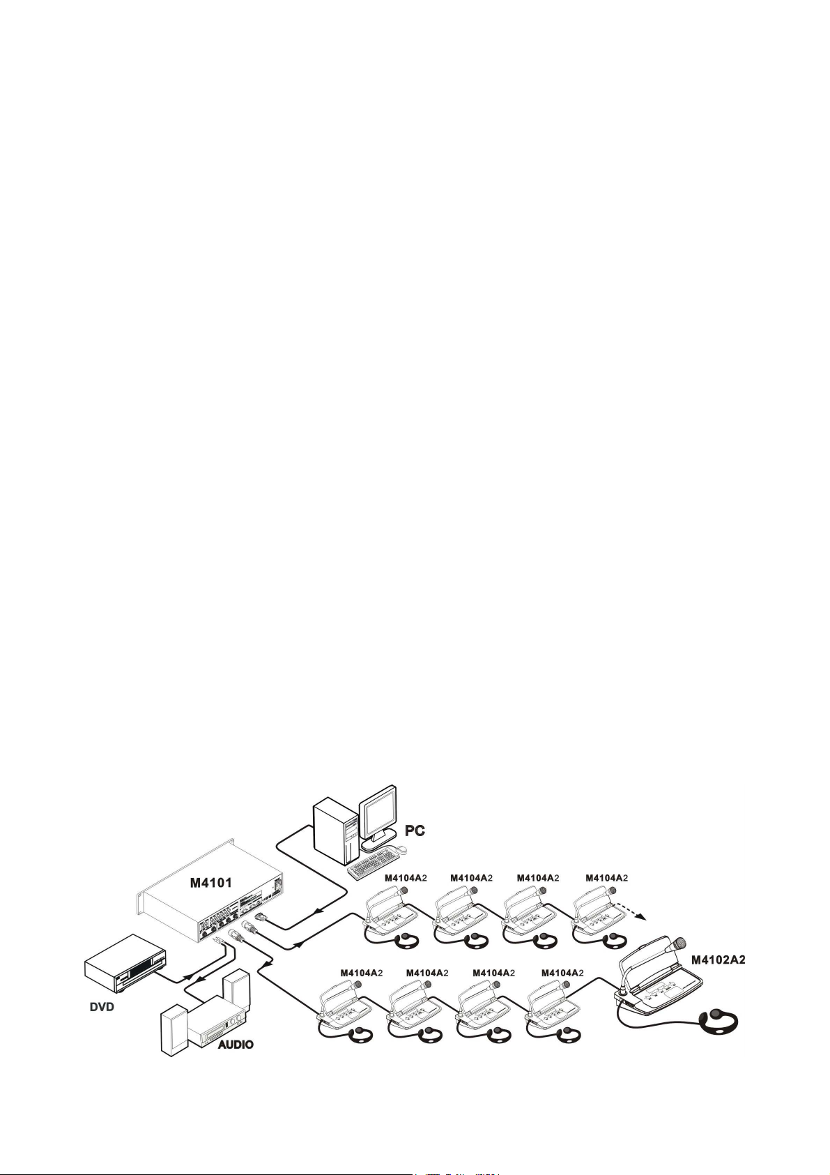
2. DCS controller
Product Instruction
CR-M4101 controller
CR-ME4000 extender
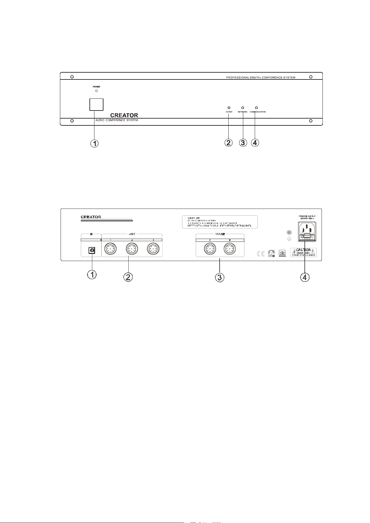
CR-M4101 controlle
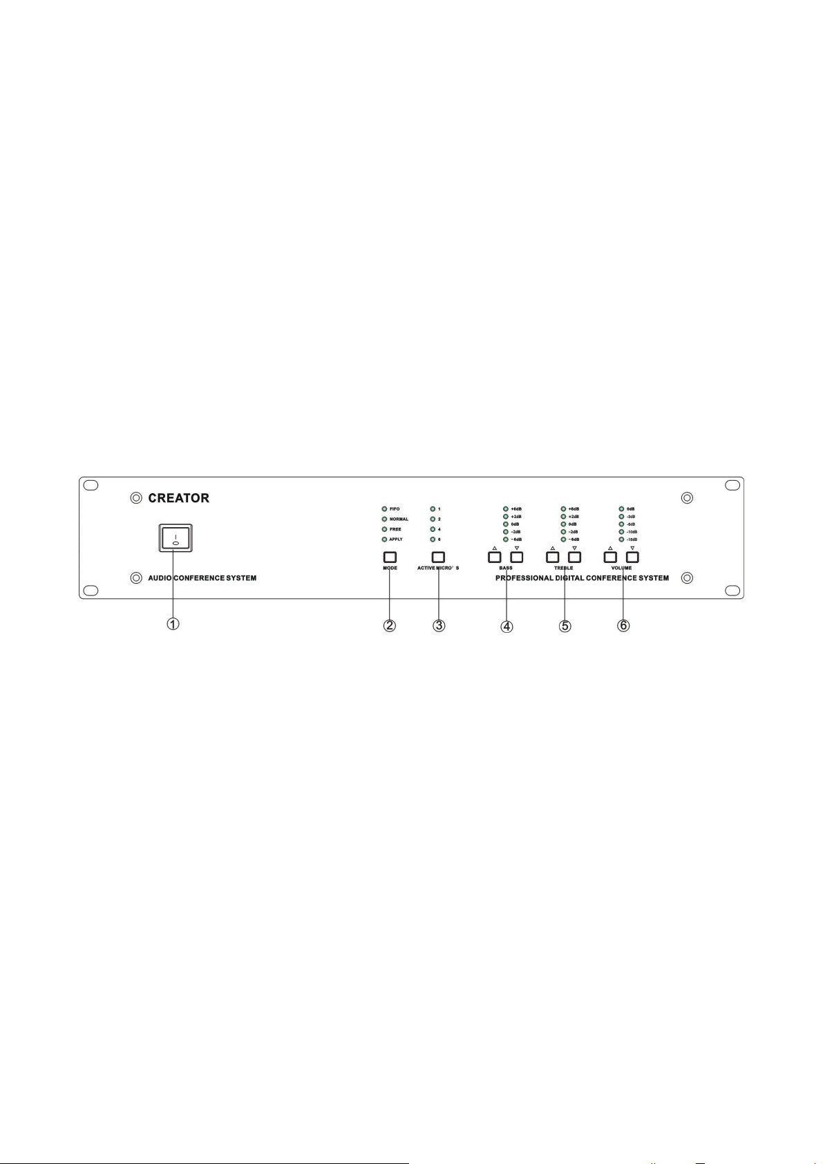
Front Panel
① POWER
② MODE
■ FIFO MODE: It is the first in first out mode with the configurable number of 1/2/4/6 speaking
units, except the chairman unit.
■ NORMAL MODE: The mode with a maximum number of active delegate units. The number of
contribution units may be set to 1/2/4/6, except the chairman unit. When the active
microphones reach the limitation, one delegate unit must be closed to leave the place for the
other who wants to speak.
■ FREE MODE: 20 active units at one time.Without any limitation from Chairman Unit.
■ APPLYMODE,delegate needs permission from Chairman unit before speaking
③ ACTIVE MICRO’S ——configure the maximum number of active microphone to be used at a
same time. Users can choose from 1, 2, 4 and 6
④ BASS ——Adjust bass up to eliminate the howling or squeal and adjust it down to get a more
clear audio reproduction
⑤ TREBLE ——Adjust treble down to eliminate the howling or squeal and adjust it up to get a more
clear audio reproduction
VOLUME ——Adjust the master volume from 1, the minimum, to 6, the maximum.
⑥
Page 9
3
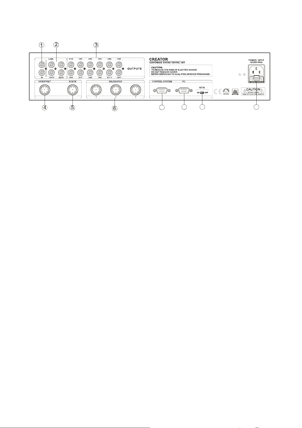
Rear Panel
7
8
9
10
① IN ——It is the audio-in connector to input the audio signal like background music
② OUT 1——It is the audio-out connector to output the audio signal to amplifier or audio recorder.
OUT 2——It is the audio connector to output the audio signal to telephone conference.
③ OUTPUTS ——There are 6 channels of audio-out connectors to output the audio signal to amplifier
or audio recorder etc.
④ INTERPRET ——It is the interface to the interpreter unit. Up to 5 interpreter units can be connected in
the hand in hand daisy-chain
⑤ ROUTE ——It is the expanded interface to the expanded control host. Up to 4096 contribution units
can access the system by daisy-chaining the expanded hosts hand in hand
⑥ DELEGATES ——It is the interface to the contribution units. There are 3 channels to access the
system, and each can link to not more than 64 contribution units in hand in hand daisy-chain. There
is no limitation for the chairman unit. It can be located anywhere in the chain
⑦ CONTROL SYSTEM ——It is the interface to the CR-PGMⅡcentral control system. Via this interface,
the CR-PGM II can cooperate with the ACS seamlessly and control the conference remotely
⑧ PC ——It is the serial control port to the console PC. With the application on the console pc, users
can control the conference system remotely
⑨ SET ID ——Set “ON” to code the contribution units for the controller and set “OFF” to run normally.
Please refer to the chapter 2.10 Coding Description for the details of coding method.
Setting: After power on, switch the SET ID to “ON”, press the speaking button of delegate
units one by one, the light will be on after setting successful.
⑩ POWER INPUT ——Power supply of 100V-240V AC
Features
1 The host itself can provide system accessing for up to 128 contribution units and can be
expanded to 4096 at the most.
2 It supports 5 interpreter units and achieves 6 languages simultaneously interpretation at a
same time including the original one
3 Communicating in the hand in hand daisy-chain, it is easy to install and maintain
4 Equipped with audio-in connector, it is able to have background music
5 Equipped with enough audio-out connectors, it is able to output the audio signal to different
audio devices
6 Limit function: Restrict present speaking units, when reach the max number, close opened
units then others can start speaking. The number can be 1, 2, 4, and 6.
7 Voice active function can automatically inspect the speaking status, and then control the video
to switch between speaker and main picture.
Page 10
4
8 FIFO mode can automatically control the active microphones.
8 P in M ALE
24V+/4
9 Working with the telephone coupler, it can open a telephone conference with remote user
10 Cooperating with the central control system, it becomes a powerful conference controller and
achieves the super function of camera auto-tracking.
11 Support voting and data managing。
12 Cover with metal material and earth well to ensure the 8000V antistatic performance
13 Rack-mountable enclosure. It can be installed in the standard 19” rack conveniently.
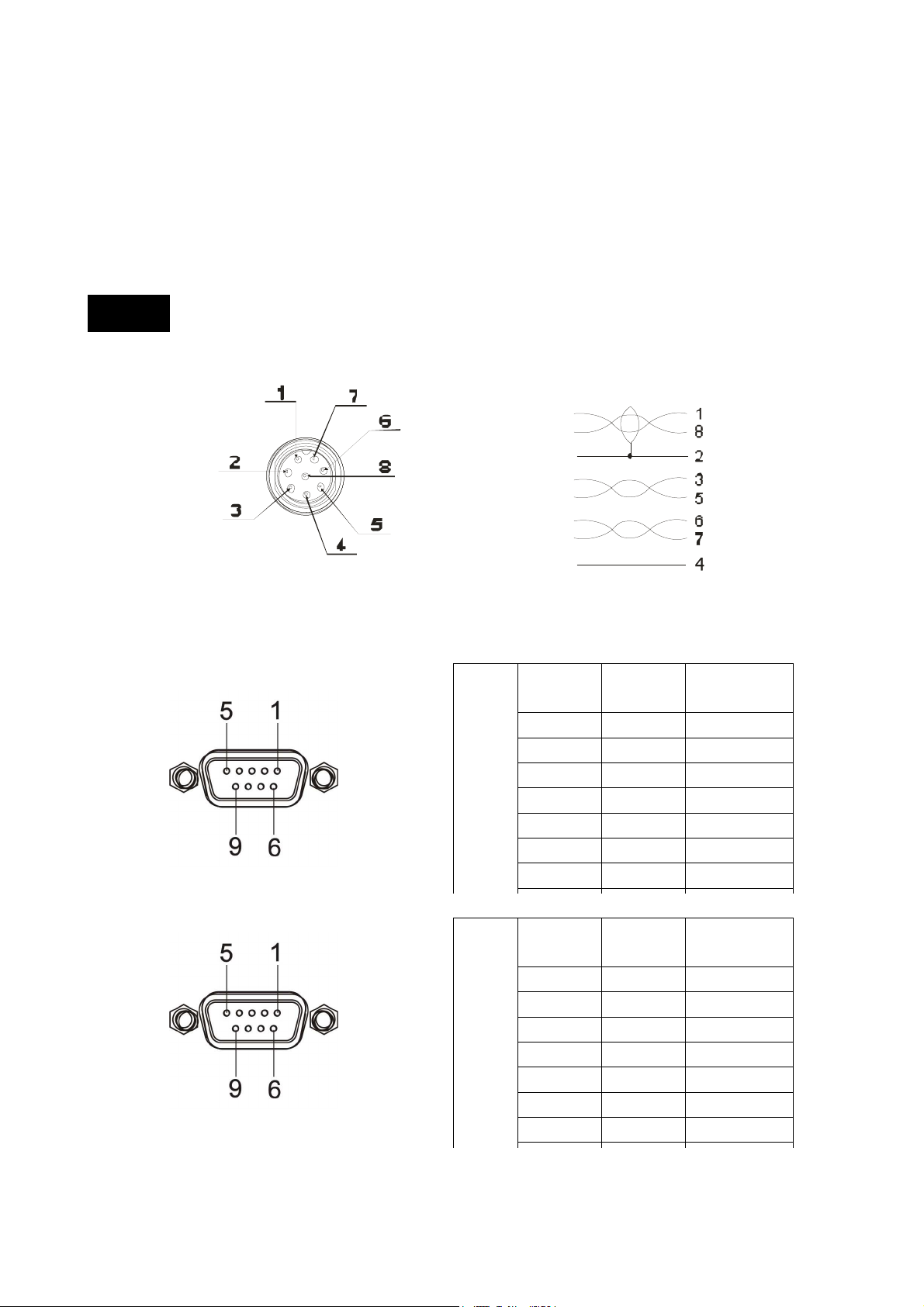
NOTICE
1.8-pin aviation connector
485A/1
485B/8
GND/2
A+ /3
A+ /5
B+/6
B- /7
2. CONTROL SYSTEM COM
3. PC COM
Control
System
PC
COM SIGNAL INSTRUCTIO
N
1 — —
2 — —
3 TXD TXD
4 — —
5 GND GND
6 — —
7 — —
SIGNAL INSTRUCTIO
N
1 — —
2 TXD TXD
3 RXD RXD
4 — —
5 GND GND
6 — —
7 — —
Page 11
5
CR-ME4000
Front Panel:
① POWER and power indicator
② ACTIVE indicator
③ NETWORK indicator
④ COMMUNICATION indicator
Rear panel:
① ID ——ID Setting
② DELEGATES——It is the interface to the contribution units. There are 3 channels to access the
system, and each can link to not more than 64 contribution units in hand in hand daisy-chain.
There is no limitation for the chairman unit. It can be located anywhere in the chain.
③ ROUTE——A is the interface to the controller. B is the expanded interface to another
expanded controller. When in a multilevel expansion, A is the interface to the front level, and B
is the interface to the next level
④ POWER INPUT——Power supply of 100V-240V AC
Features
1.8-pin aviation connector
2. Working with CR-M3201 control host to expand the contribution units in system
3.Input voltage between 100-240V, it can endure 3500V high voltage
4. Cover with metal material and earth well to ensure the 8000V antistatic performance
5. Rack-mountable enclosure. It can be installed in the standard 19” rack conveniently
Page 12
6
Technical Parameter
Technical Parameter CR-M4101 CR-ME4000
Power supply 100-240V 100-240V
Static consumption 10W 10W
Nominal power
consumption 350W 350W
Output power ≤110W/24V ≤110W/24V
Impedance:100Ω
Audio output
MIC input
Frequency response 60-8kHz 60-8kHz
(S/N) > 80dB > 80dB
Harmonic distortion < 0.5% < 0.5%
Harmonic distortion at overload <1% <1%
Crosstalk attenuation at 1kHz >50dB >50dB
Weight 6.5KG 6KG
Dimension 483L *275W *88H (mm) 483L * 275W *88H (mm)
Colour Grey Grey
mode:unbalanced
Impedance:100kΩ
Electriclevel:-60dB
mode:unbalanced
Impedance:100Ω
mode:unbalanced
Impedance:100kΩ
Electriclevel:-60dB
mode:unbalanced
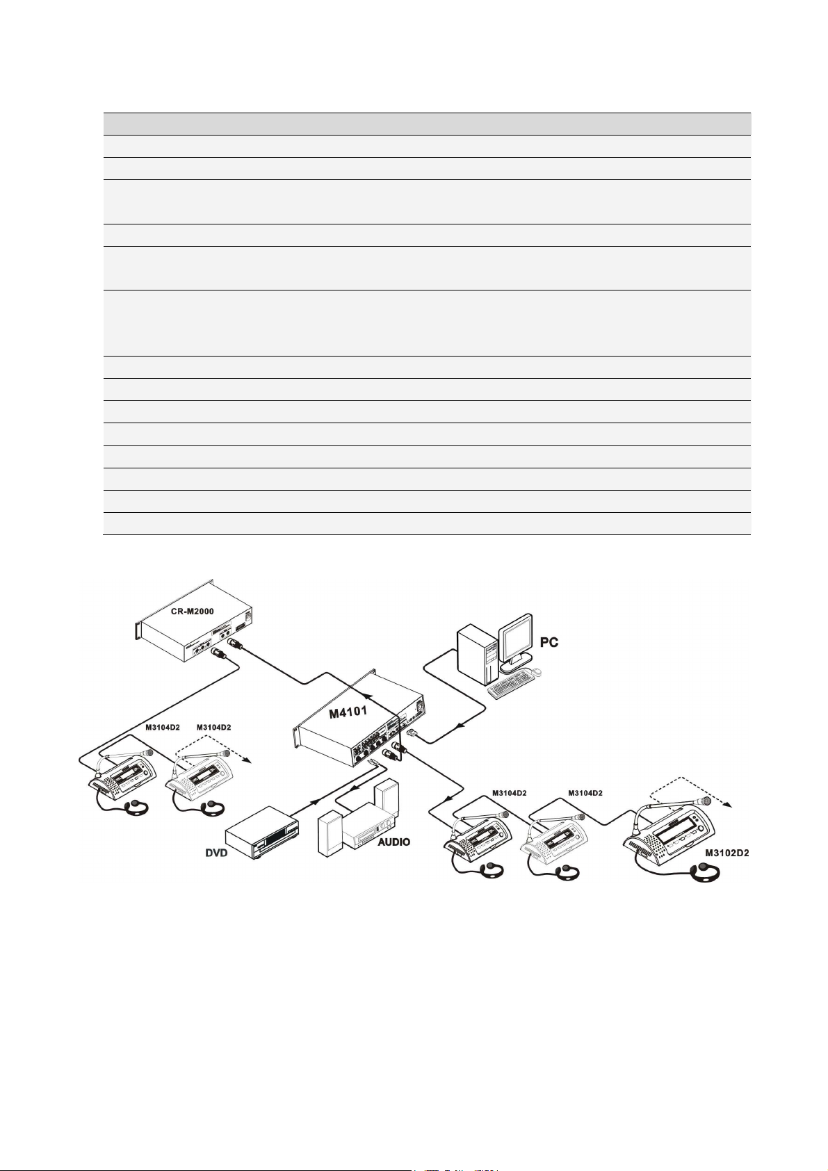
Diagram
Setting ID for conference units:
1. The ID setting for conference units means that, every conference unit in the system (including
interpretation & speech unit) was given the only address for being discerned by the host.
2. setting the conference units as following: after connection finished, turn on the host power, and set
the ‘SET ID’ to ‘ON’, and press speech of the speech & interpretation unit one by one, the light of MIC will
be on, until all the lights are on, we could set the ‘SET ID’ to ‘OFF’, when all the lights of MIC are off, the
system will work under the normal mode
Page 13

7
3. DCS Speaking Unit
Product Instruction
Model Name Externality MIC Key Voting Channels
Switch
CR-M4104A1 Delegate Unit Fold-away √ × × ×
CR-M4102A2 Chairman Unit Fold-away √ √ × √
CR-M4104A2 Delegate Unit Fold-away √ √ × ×
CR-M4102B Chairman Unit Table-Top √ × × ×
CR-M4104B Delegate Unit Table-Top √ × × ×
CR-M4102C1 ChairmanUnit Embedded √ × × ×
CR-M4104C1 Delegate Unit Embedded √ × × ×
CR-M4102C4
CR-M4104C4
CR-MC4032B
CR-MC4034B
CR-M4102D2 Chairman Unit Slide √ √ × √
CR-M4104D2 Delegate Unit Slide √ √ × √
CR-TP4102D Chairman Unit Slide √ √ × √
CR-M4102E Chairman Unit Table-Top √ × × ×
CR-M4104E Delegate Unit Table-Top √ × × ×
CR-M4102F Chairman Unit Embedded √ √ × √
CR-M4104F Delegate Unit Embedded √ √ × √
Chairman
Voting Unit
Delegate
Voting Unit
Chairman
twinaudio box
Delegate
twinaudio box
Embedded × √ × ×
Embedded × √ × ×
× × × ×
× × × ×
LCD
Page 14
8
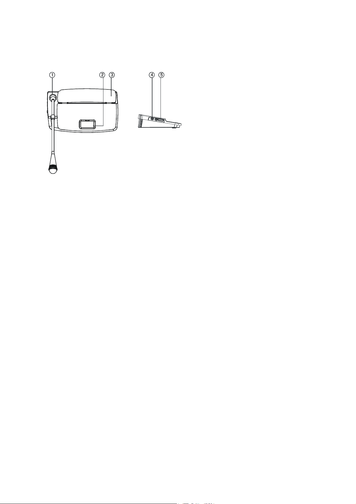
CR-M4104A1
Features
① Microphone: Pluggable, easy to transport and maintain
② MIC button: Press it to open the microphone and repress it to close the microphone.
③ Build-in flat panel loudspeaker: It will automatically mute while the microphone opens.
④ Earphone jack: Install and connect the earphone for DCS here.
⑤ Volume adjustment: Adjust the volume of the contribution unit
Features::::
1. Voting function integrated
2. 8-pin aviation connector
3. Pluggable unidirectional microphone with red ring indicator
4. Knob pin MIC pole
5. 2M cable for each unit
6. Build-in flat panel loudspeaker and earphone jack with excellent audio quality and adjustable
volume control.
7. The power of delegate unit and chairman unit are supplied by the central control unit with 24V
safety current.
8. Radio disturbance prevention
9. Communicating in the hand in hand daisy-chain or “T”, it is easy to install and maintain.
Page 15
9
Diagram
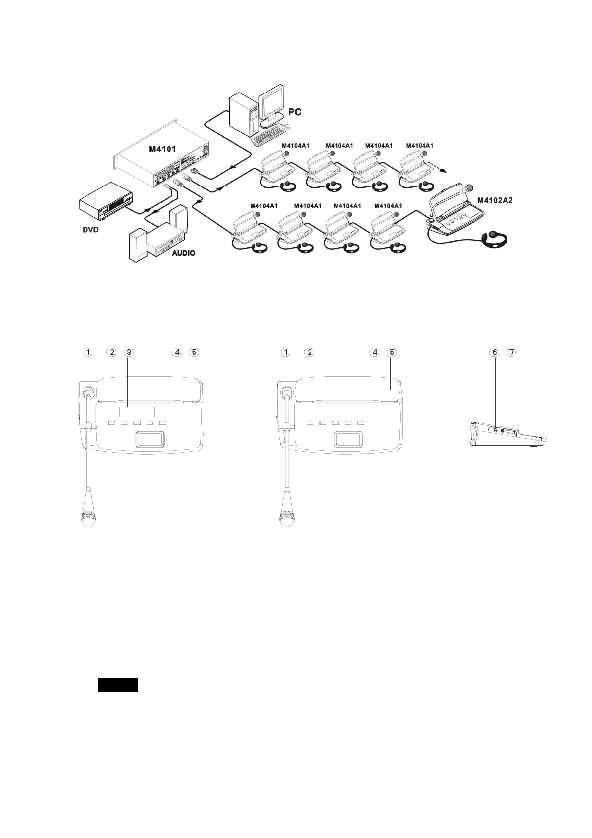
CR-M4102/4A2
Features:
CR-M4102A2 Front View CR-M4104A2 Front View Side View
① Microphone: Pluggable, easy to transport and maintain
Multi② voting buttons
——For/against: buttons 2/3/4 stand for For/Abstain/Against, respectively.
——Multiple election: buttons 1/2/3/4/5 can stand for different candidates, respectively.
——Evaluation Poll: buttons 1/2/3/4/5 stand for 5 level /-/0/+/++, from low to high.
NOTICE
Button 4 on the chairman unit has a special function of intermission.
The chairman can press to temporarily close all the microphones on delegate units and
release it to resume the conference.
The conference holder can press the START button on the chairman unit to start voting. At this
time, all the contribution units will sound “Di” and the button 1 will flash to ask for confirmation.
Page 16
Then, the delegates should press the button 1 to confirm and start voting.
Their last choice on the buttons will be considered as their final decision and will be indicated by
the button indicator. When the conference holder press the STOP button on the chairman unit,
the voting is finished and all the contribution units will sound “Du” in a same time. Pressing
button 4 for 2 seconds, to return the normal discussion status.
③ LCD displayer
④ MIC on/off
⑤ Build-in flat panel loudspeaker
⑥ Earphone jack
⑦ Volume adjustment
Features
1, voting function integrated.
2, 8-pin aviation connector
3. Pluggable unidirectional microphone with red ring indicator.
4, 2M cable for each unit
5, Knob pin MIC pole
6, Build-in flat panel loudspeaker and earphone jack with excellent audio quality and adjustable
volume control.
7, Chairman Unit has the function to approve or deny the talking request from delegate units.
8, Chairman Unit is not limited by the active microphone limitation.
9, Chairman Unit can cut the microphone of delegate units at any time to manage and control the
whole conference conveniently
10, There is no limitation for the chairman unit. It can be located anywhere in the daisy chain. Power
supplied by the central control unit with 24V safety current.
11, the flat panel loudspeaker will automatically mute to avoid howling when the microphone turns
on.
12, communicating in the hand in hand daisy-chain or “T”, it is easy to install and maintain.
Diagram
10
Page 17

CR-M4102/4B
Features
CR-M4102B Front View CR-M4104B Front View Rear View
① MIC jack
② PRIOVITYKey
③ POWER
④ MIC ON/OFF
⑤ MIC indicator light
⑥ Build-in loudspeaker
⑦ Volume adjustment
⑧ Earphone jack
⑨ Link jack
⑩ Cable
Features
1, voting function integrated.
2, 8-pin aviation connector
3. Pluggable unidirectional microphone with red ring indicator.
4, 2M cable for each unit
5, Knob pin MIC pole
6, Build-in flat panel loudspeaker and earphone jack with excellent audio quality and adjustable
volume control.
7, Chairman Unit has the function to approve or deny the talking request from delegate units.
8, Chairman Unit is not limited by the active microphone limitation.
9, Chairman Unit can cut the microphone of delegate units at any time to manage and control the
whole conference conveniently
10, There is no limitation for the chairman unit. It can be located anywhere in the daisy chain. Power
supplied by the central control unit with 24V safety current.
11
Page 18

Diagram
CR-M4102/4E
Features
Side View Front View Side View
2
3
1
4
M
I
C
P
F
F
H
O
N
O
N
/
O
E
5
D IG ITA L C ON FE REN CE S YSTE M
D IG ITA L C ON FE REN CE S YSTE M
D IG ITA L C ON FE REN CE S YSTE MD IG ITA L C ON FE REN CE S YSTE M
8
7
1
6
① Earphone jack
② MIC jack
③ Build-in loudspeaker
④ MIC indicator light
⑤ MIC on/off
Rear View
12
Page 19

⑥ Volume adjustment
⑦ Cable
⑧ Link connector
Features
1, voting function integrated.
2, 8-pin aviation connector
3. Pluggable unidirectional microphone with red ring indicator.
4, 2M cable for each unit
5, Knob pin MIC pole
6, Build-in flat panel loudspeaker and earphone jack with excellent audio quality and adjustable
volume control.
7, Chairman Unit has the function to approve or deny the talking request from delegate units.
8, Chairman Unit is not limited by the active microphone limitation.
9, Chairman Unit can cut the microphone of delegate units at any time to manage and control the
whole conference conveniently
10, There is no limitation for the chairman unit. It can be located anywhere in the daisy chain. Power
supplied by the central control unit with 24V safety current.
11, the flat panel loudspeaker will automatically mute to avoid howling when the microphone turns
on.
Diagram
13
Page 20

Embedded Unit
CRE ATOR
4
0
m
m
4
0
m
m
4
Features
CR-M4102C1Front View CR-M4104C1Front View
12 9 mm
C REATOR
MIC /BREA K
1
2 3
4 0. 00 mm
1
12 9m m
2 3
CR-M4102C4Front View CR-M4104C4Front View
12 9mm
CRE ATOR
4
12 9 mm
CR-MC4032B/CR-MC4034B
8
7
121.0 mm
CRE ATOR
40 mm
MIC
8
86.0mm
5
① MIC jack
② Earphone jack
③ MIC——ON/OFF,long press for 3 seconds of Chairmane unit can stop active delegate unit.
④ Multi voting buttons
“1,2,3,4,5”
——For/against: buttons 2/3/4 stand for For/Abstain/Against, respectively.
——Multiple election: buttons 1/2/3/4/5 can stand for different candidates, respectively.
——Evaluation Poll: buttons 1/2/3/4/5 stand for 5 level /-/0/+/++, from low to high.
14
24.5 m m
7
6
Page 21

NOTICE
Button 4 on the chairman unit has a special function of intermission. The chairman can press it
to temporarily close all the microphones on delegate units and release it to resume the
conference.
The conference holder can press the START button on the chairman unit to start voting. At this
time, all the contribution units will sound “Di” and the button 1 will flash to ask for confirmation.
Then, the delegates should press the button 1 to confirm and start voting.
Their last choice on the buttons will be considered as their final decision and will be indicated by
the button indicator. When the conference holder press the STOP button on the chairman unit,
the voting is finished and all the contribution units will sound “Du” in a same time. Pressing
button 4 for 2 seconds, to return the normal discussion status.
⑤ NEXT——connect to next audio box
⑥ LINK——connect to CR-M4101/NEXT
⑦ MIC——connect to CR-M4102/4C1
⑧ VOTE——connect to CR-M4102/4C4
Diagram
Features
1, voting function integrated.
2, 8-pin aviation connector
3. Pluggable unidirectional microphone with red ring indicator.
4, 2M cable for each unit
5, Knob pin MIC pole
6, Build-in flat panel loudspeaker and earphone jack with excellent audio quality and adjustable
volume control.
7, Chairman Unit has the function to approve or deny the talking request from delegate units.
8, Chairman Unit is not limited by the active microphone limitation.
15
Page 22

CR-M4102/4F
Features
CR-M4102 Front View CR-M4104F Front View
1
2
6
1
6
3
4
5
3
4
5
① MIC jack
② LCD displayer
③ Earphone jack
④ MIC on/off
⑤ Multi voting buttons
“1,2,3,4,5”
——For/against: buttons 2/3/4 stand for For/Abstain/Against, respectively.
——Multiple election: buttons 1/2/3/4/5 can stand for different candidates, respectively.
——Evaluation Poll: buttons 1/2/3/4/5 stand for 5 level /-/0/+/++, from low to high.
NOTICE
Button 4 on the chairman unit has a special function of intermission. The chairman can press it
to temporarily close all the microphones on delegate units and release it to resume the
conference.
The conference holder can press the START button on the chairman unit to start voting. At this
time, all the contribution units will sound “Di” and the button 1 will flash to ask for confirmation.
Then, the delegates should press the button 1 to confirm and start voting.
Their last choice on the buttons will be considered as their final decision and will be indicated by
the button indicator. When the conference holder press the STOP button on the chairman unit,
the voting is finished and all the contribution units will sound “Du” in a same time. Pressing
button 4 for 2 seconds, to return the normal discussion status.
⑥ IC card influence zone——IC card for registeration
16
Page 23

Diagram
Features
1, 8-pin aviation connector
2, Pluggable unidirectional microphone with red ring indicator.
3, 2M cable for each unit
4, Knod pin MIC pole
5, Earphone jack
6, IC card registration
7, voting function integrated.
8, Chairman Unit can cut the microphone of delegate units at any time to manage and control the
whole conference conveniently
9, Chairman Unit has the function to approve or deny the talking request from delegate units.
10, power supplied by the central control unit with 24V safety current.
11, There is no limitation for the chairman unit. It can be located anywhere in the daisy chain.
12, communicating in the hand in hand daisy chain or “T”, it is easy to install and maintain.
17
Page 24

CR-M4102/4D2
4561234
Features
CR-M4102D2 Front View CR-M4104D2 Front View SideView
1 2
① MIC jack
② Multi-function voting key
——Conference vote, three buttons denote approve, disclaim and oppose
——election: 5 buttons means different candidates
——conference evaluate 5 buttons means “、-、0、+、++” level
3
NOTICE: Long press the number 1 button of chairman unit to start vote, there would be a sound to
confirm. After voting, press number 5 to check the result. Long press the number 5 again
back to conference mode.
Priority for Chairman Unit
Shield function——Shield function——long pressing number “4” to shield all the
delegate units , not press to recover last status:
Cut off function——long pressing switch button to cut off all the delegate units , there
would be a sound to confirm.
Chairman LCD language setting:
Long press number “3” to set language. Press 1 for Chinese, press 5 for English, press 3
back to conference mode.
The conference holder can press the START button on the chairman unit to start voting. At
this time, all the contribution units will sound “Di” and the button 1 will flash to ask for
confirmation. Then, the delegates should press the button 1 to confirm and start voting.
Their last choice on the buttons will be considered as their final decision and will be indicated by
the button indicator. When the conference holder press the STOP button on the chairman unit,
the voting is finished and all the contribution units will sound “Du” in a same time. Pressing
button 4 for 2 seconds, to return the normal discussion status.
NOTICE
MIC jack①
Mutil② -function key
LCD screen display③
④ Earphone connector
18
Page 25

Content of LCD
Conference
Diagram
MODEL
MODE
voting
M4102D M4104D
Number of Voting man
Max number of speaking man
Tips when voting
Result when finish voting
Reveal DCS Delegate
Process voting
Show the result
Features
1, There are 5 multi-function buttons to process voting.
2, Chairman Unit’s LCD can show all the information about result of voting and sign in, number of
voting man etc.
3, Chairman Unit can start, stop voting or sign in. Pause or deny the speak function of all the
delegate units.
4, 8-pin aviation jack
5, Indicator of speaking permit
6,2M cable for each unit
7, Knob pin MIC pole
8, Build-in loudspeaker, earphone jack, volume adjustment knob.
9, Chairman Unit has the function to approve or deny the talking request from delegate units
10, There is no limitation to chairman unit speaking.
11, the flat panel loudspeaker will automatically mute to avoid howling when the microphone turns
on.
12, Chairman Unit can manage and control the whole conference conveniently.
13, the indicator can show the real-time voting status.
14, Delegate unit could apply or cancel speaking
19
Page 26

CR-TP4102D
Features
1
2
4
3
7
5
6
1. Microphone: pluggable, easy to transport and maintain
2. 3.5” LCD screen
3. MIC button: press it to open the microphone and repress it to close the microphone
4. ——Cut off the delegate’s speaking temporarily, ——Cut off the delegate’s speaking
NOTICE Priority:
Screen——Press ,screen the delegates speaking temporarily, release it to return normal.
Cut off——Press ,close all the delegates speaking channel
5. Earphone port.
6. Volume adjust knob
7. USB port——Mini USB port,download and upgrade the firmware.
NOTICE:
Approach for downloading program:
a) Connect a computer to CR-TP3102D well via USB cable.
b) Open the software of Touchpanel.
c) Choose the menu “File””Project”, open the program of TP3102D.
d) Under the menu of “Project”, choose “Upload Program” for uploading and end.
20
Page 27

Touch Panel Instruction:
Meeting mode
F 3-1
Meeting mode: Image adjust and Information
Double click the video window; it will turn to full
screen. Single click to return.
PIP:::: Go with camera to achieve auto tracking, the
picture in LCD is the same as that of cameras. Also it
can display the video signal from other devices
connected to the CR-MV200.
Image adjust::::In this operation interface, click
“up, Down, left, right, zoom +, zoom -”
to control theCamera.
The video will show in the Chairman unit by
real-time monitoring
F 3-2
NOTICE
When the camera is controlling by the chairman unit of CR-TP3102D, the conference host of CR-M3101
sends the some coeds to PGMII as below:
Bauderate:38400B/ps
Up: A0 00 10 00 07 01 FF FF FF AF EA
Down: A0 00 10 00 07 02 FF FF FF AF E9
Left: A0 00 10 00 07 03 FF FF FF AF E8
Right: A0 00 10 00 07 04 FF FF FF AF E7
Zoom +: A0 00 10 00 07 06 FF FF FF AF E5
Zoom -: A0 00 10 00 07 05 FF FF FF AF E6
Stop: A0 00 10 00 07 09 FF FF FF AF E2
The codes about Up, Down, Left, Right , Zoom + or Zoom – will be sent to the conference host when
touch the correlational button in the touchpanel of CR-TP3102D , and the codes of “Stop” will be sent
when fingers leave the touchpanel.
Information Note:
21
Page 28

Voting mode
Information Note::::Show the max attendees
set in the conference host and the number of
speakers
F3-3
Voting mode: In this mode, user can choose
“Approve, Abstain, and Oppose”, start voting and
end it, then see the result.
When the voting begins, all delegate units will beep
which means they are ready for voting. The
delegate unit can remember the last press and take
it as the effective vote. The result will be displayed
on Chairman Unit.
F3-4
Besides the voting caused by TP4102D, there are several other methods for voting, but those
Should be controlled by the conference system which was installed in PC when start and end,
According to the conference host, sending to every conference speech unit. The methods are
As following:
——Conference vote, three buttons denote approve, disclaim and oppose
——election: 5 buttons means different candidates
——conference evaluate 5 buttons means “、-、0、+、++” level
Voting Result Voting selection Evaluation mode
NOTICE
The last press is in effect; all the result will be showed on Chairman Screen.
22
Page 29

Language selection
Language selection: the user can select
the English, Simple Chinese, or traditional
Chinese.
Further more, because the chairman
touchpanel is programmable, the user can
enter any language as you want by
programming. In this way, you can turn
the panel into the French, German, Russian,
Spainish, Portuguese, Italian and so on.
F3-5
NOTICE All the setting we set on the operation interface after starting up, the device will save the last
setting, when start next time, the device will display the operation interface last time we save.
For example, now we set the language of the operation interface to English, shutdown, and
then start up, the displaying operation interface will be English.
ID Setting
Switch the ID set “ON” behind CR-M4101
controller, page 3-7 will be displayed. After
setting, switch it off then the system turns to
“Meeting mode”, please refer to “CR-M4101
2.6 ID set”
F3-6
Features
1, 3.5 inches TFT LCD touch panel with real colors 320 x 240 pixels and support picture in picture
function.
2, Slide style design, solemn black and silvery wiredrawing, Intimate having dust prevention designs.
3, Adopt 32-bit ARM9 processor.
4, Match a video/audio adapter (CR-MV200), it can rotate signal of various video equipment to
display on the LCD.
5, be not restricted by spokesman number; Have full powers controlling the order of Convention.
6, Assort the camera to realize the Auto tracking with the conference unit.
7, Cable connects in the hand in hand pattern, easy to assemble and maintain.
8, Speech pattern: normal (the number restricts), FIFO.
9, under the ballot mode, there are choice of approves of, abstains from voting or veto. Also, may
initiate stop casting a ballot and sign in.
10, Support simplified Chinese, traditional Chinese and English operation language.
11, three shortcuts buttons on the panel, which can suspend or cancel all the delegate unit’s words,
and have the function of turning on microphone.
23
Page 30

12, clearly earphone output and digital attunement technology and professional DSP chips and
timbre improve circuit,
13, EQ technology adopted ensures quality voice output.
Diagram
24
Page 31

Technical Parameter
parameter CR-M4102/4A CR-M4102/4B1
Power supply DC24V( host power) DC24V( host power)
Prot DIN 13P/8P DIN 8P
Power
consumption 3W 3W
Earphone
output 9dBu,8-32Ω,3.5mm 9dBu,8-32Ω,3.5mm
Loudspeaker
power 2W 2W
Transducer type Electrets condenser Electrets condenser
Directional
pattern Cardioids Cardioids
(S/N) > 80dB > 80dB
Crosstalk > 80dB > 80dB
Distortion < 0.10% < 0.10%
Frequency
response 60-8kHz 60-8kHz
Equivalent
noise ≈20dB SPL ≈20dB SPL
Max SPL 105dB(3% threshold ) 105dB(3% threshold )
Sensitivity -22dBv/Pa -22dBv/Pa
Dimension
(mm) 247L*155W*60H 127L*146W*62H
Color Black
Grey
25
Page 32

parameter CR-M4102/4C1 CR-M4102/4C4 CR-M4102/4D2 CR-TP4102D
DC24V
Power
Prot RJ45 DIN 13P/8P
Power
consumption
Earphone
output
Loudspeake
power × × 2W
Transducer
type × × Electrets condenser
Directional
pattern Cardioids × Cardioids
(S/N) > 80dB
Crosstalk > 80dB
Distortion < 0.10%
Frequency
response 60-8kHz
Equivalent
noise ≈20dB SPL
Max SPL 105dB(3% threshold )
Sensitivity -22dBv/Pa
Dimension
(mm) 129L*40W*42.5H 129L*40W*42.5H
Color Grey
(host power) DC24V(host power)
3W 3W 4W
9dBu,8-32Ω,
3.5mm × 9dBu,8-32Ω,3.5mm
218L*138W*56H 218L*138W*56H
Grey
Black
Grey
26
Page 33

4. DCS Simultaneous Interpretation
CR-M4103E3
Features
CR-M4103E3Front View Side View
① Volume adjust
② Earphone volume adjust
③ Build-in loudspeaker
④ IN——Input channel select
⑤ OUT——Output channel select
⑥ FLOOR-RELAY——floor and relay switch
⑦ MIC ON/OFF
⑧ COUGH——Cough prevention
⑨ A、B——Channels shortcut keys,Long press 3s to be confirmed.
⑩ a、b——Channels shortcut keys,Long press 3s to be confirmed.
LCD displayer——320X64 resolution,input channel and language displays on the left,while
output channel and language on the right.
MIC socket
MIC volume indicator
ENTER——press to enter setting menu.
MIC jack
Earphone jack
27
Page 34

IN
192
01
7 8
English English
02:
fre
04:
TI ME:
chi
00:00
01:
eng
OU T
01
0 3:
ru s
6
① Input channel
② Output channel
③ Channel A and its lanuage
④ Channel B and its lanuage
⑤ Channel a and its lanuage
⑥ Channel b and its lanuage
⑦ Input language
⑧ Output language
⑨ Max timing99m59s
3
4 5
Setting menu
Interpretation unit languages quantity, channels and languages and whether the output channel lock and
other functions should be set in the setting menu of the interpretation unit.
1. Entering the setting menu
Press‘ENTER’ for 5 seconds, and then display the setting
menu of the interpretation unit. Enter the setting number,
as graph 4.1; the password was made of 4 numbers.
F4.1
circumgyrate“OUT SELECT”to set password,press“ENTER” to confirm.See F4.2
Original password is 2468
PassW : 000ord 0
Enter
F4.2
2、Setting of interpretation unit
CH MAP:Channel, language setting
OUT SET:Interlock/uninterlock of channel setting
PassWord:Password stting
EXIT:Exit setting menu, see F4.3
CH
MAP
P a s sW o r d
F4.3
Exit
OUT
EXTT
SET
28
Page 35

2.1、CH MAP setting
01
See F4.4,circumgyrate “OUT SELECT”to“CH MAP”,press “ENTER”
CH
MAP
OUT
P a s sW or d
F4.4
Circumgyrate “OUT SELECT”to set CH TOTAL, MAX12 channels.
CH
MAP
Total:
CH
F4.5
Choose“ENTER”to set channel and languages, 63 different languages can be choosed, see F4.6
CH
MAP
01
CH
2.2、OUT SET setting,see F4.7
English
F4.6
SET
EXTT
CH
MAP
OUT
P a s sW o r d
F4.7
OUT
C o n t r o l
OUT
C o n t r o l
Afterting seeting, you can choose to interlock channels or not, see F4.10
OUT
C o n t r o l
Afrikaans
11
En ter
F4.8
Afrikaans
11
En ter
F4.9
0 1
English
Enter Exit
SET
EXTT
E x it
E x i t
Protect
Out
F4.10
CH
F4.11
Set
Mode
Freeness
29
Page 36

2.3、Passsword setting
0 1
Circumgyrate “OUT SELECT”to“PassWord”,see F4.12
CH
MAP
OUT
P a s sW o r d
F4.12
Choose “ENTER”to F 4.13
SET
EXTT
New PassW :0000ord
Enter Exit
F4.13
New PassW : 000ord 0
Interpreter unit can be changed to monitoring unit,which is for the monitoring of the channel only,can’t
be used to turn on the mic,and no output channel select,no CALL function,can only receive a CALL
request,and display on the LCD,when press CALL,it turns back.
Enter Exit
F4.14
Monitor unit
Setting:
Press ENTER for seconds when the power on, and release to change it to monitoring unit, if interpreter
unit is needed, just turn off the power and restart it.
NO
Floor
Total
00
MONITOR
NO Apply
F 4.15
Call Room
Spanish
F 4.16
Features
1. Earphone and monitor integrated
2. 8-pin aviation connector
3. Capacitance MICwith twin color indicator.
4. 2M cable itself
5. Knob pole
6. Build-in loudspeaker, earphone jack, volume adjust.
7. CR-M4101 controller supports 36 interpreter units and 12 languages simultaneously
30
Page 37

interpretation at a same time including the floor one.
8. Direct or indirect interpretation available.
9. Interpretation units can be made of interpretation system.Interlock channels ensures that each
output channel can carry only one language at one time.
10. Help press
11, Cough prevention
12 Can change the interpreter unit to monitoring unit.
13, power supplied by the central control unit with 24V safety current.
Techinical Parameter
Technical Parameter CR-M4103E3
Power DC24V(supplied by host)
Prot 8P
Power consumption 2W
Earphone output 9dBu,8-32Ω,3.5mm
Loundspeaker Power 2W
Transducer type Electrets condenser
Directional pattern Cardioids
(S/N) > 80dB
Crosstalk attenuation > 80dB
Distortion <1%
Frequency response 10-24kHz
Equivalent noise ≈20dB SPL
MAX SPL 105dB(3% threshold)
Sensitivity -22dBv/Pa
Dimension 290L *130W*100H (mm)
Color Grey
Diagram
31
Page 38

5. DCS IR Language Distribution System
Product Description
CR-IR2000-12 IR Language Distribution System transmitter controller
CR-IR2001-12 IR Language Distribution System Radiator unit
CR-IR2002-12 IR Language Distribution System Receiver unit
CR-IR2000-12 IR Language Distribution System Transmitter
Controller
Destription:
1
① POWER
② Input channel indicators: Indicates the working channel from 1 to 6 in red and from 7 to 12 in
green.
① INPUTS ——11+1 Channel audio inutputs, connect with conference host outputs.
② OUTPUTS ——11+1channel audio outputs, can send 12 audio outputs to recorder or amplifier
and other audio devices.
③ SINGAL OUTPUTS——connect with IR radiator board.
④ TEST ——Test button.
⑤ POWER INPUT ——Power input, support with AC100V~240V input.
2
Features:
1. Adopt high frequency(2M-8MHz).
2. The test function can create 12 various frequency audio signals for system test.
3. 100-240V power supply. 3500V high current test.
4. Cover with metal material and earth well to ensure the 8000V antistatic performance
32
Page 39

CR-IR2001-12 IR Radiator board
Function:
① LOW/HIGH ——power magnitude selector for IR radiation
② IN ——the interface to connect the SINGAL OUTPUTS of the transmitter host or the ’OUT’ of
the radiator board.
③ OUT ——connect with next ‘IN’.
④ POWER INPUT——support with AC100V~240V input.
⑤ IR region
Features:
1. Powerful ability of IR radiation (50 meters at 25W or 30 meters at 15W).
2. Support with 4 IR radiator board class-connection.
3. Easy installation with free attachable bracket or triangle bracket
4. Half radiator angle: ±22°
33
Page 40

CR-IR2002-8/12 IR Receiver unit
Function:
① Volume knob for adjustment
② Earphone (3.5mm), connect with the monitor earphone.
③ IR receiver window.
④ Power switch button.
⑤ Display monitor, display language channel.
⑥ POWER——Power indicator. The indicate light is green and always on when starting up, but it
will wink red when the battery is low.
⑦ Channel——Language receiver channel selector.
⑧ IR Sensor, for receiving the IR signal.
⑨ Suspending hole.
Features:
1. Cooperate with CR-P2 headphone.
2. Adopt the special anti-noisy technique to reduce the noisy while switching, 8-12 selectable
channel.
3. Ajustable volume.
4. The quantity of the receiver unit is not limited in the covered area of IR radiation
5. Adopt PLL technique for improving received stability to up to 10PPM
6. Convenient to keep. Strap and hang it up on the neck or just put it in the pocket
34
Page 41

Parameters:
IR language distribution system
Model CR-IR1000-6
Power supply 100-240V Power supply AAA NIMH rechargeable battery
Power
consumption 25W (selectable)
Crystal Crystal control
Modulation PPL, narrow band Modulation FM
Carrier wave
frequency 2M—20MHz (BAND4)
Pre-emphasis
Deviation ±6kHz(peak value ± 7kHz) Signal reversion 150ms
Total harmonic
distortion
SNR >80dB SNR > 80dB
Frequency
60—12KHz Am restraint > 45dB
Input Sensitivity
RF output 2 BNC, 100mV RMS
RF output
impedance
Dimension 430L * 275W * 90H (mm) Dimension 108L* 62W * 28H (mm)
Weight 6.8KG Weight 0.4KG
Color Black Color Black
Model CR-IR2000-12 Model CR-IR2002-12
Power supply 100-240V Power supply AAA NIMH rechargeable battery
Power
consumption 15W/25W (selectable)
Crystal Crystal control
Modulation PPL, narrow band Modulation FM
Carrier wave
frequency 2M—20MHz (BAND4)
Pre-emphasis
Deviation ±6kHz(peak value ± 7kHz) Signal reversion 150ms
Total harmonic
distortion
SNR >80dB SNR > 80dB
100µs
<1% Total harmonic
50mV-1.5V Maximum sound
50Ω
100µs
<1% Total harmonic
Model CR-IR1002-6
Receiving
frequency
Intermediate
frequency 10.7MHz
Nominal
frequency
difference ±6kHz
Peak value
deviation ±8kHz
distortion <1%
pressure level 110dB
Frequency
response 608 kHz
Distortion <1.5%
Receiving
frequency
Intermediate
frequency 10.7MHz
Nominal
frequency
difference ±6kHz
Peak value
deviation ±8kHz
distortion <1%
2M-20MHz , 40KHz channel
separated
2M-20MHz , 40KHz channel
separated
35
Page 42

Frequency
response 20~10KHz Am restraint > 45dB
50mV-1.5V Maximum sound
Input Sensitivity
RF output 2 BNC, 100mV RMS
RF output
impedance
Dimension 483L *344W* 88H (mm) Dimension 105L *50W * 19H (mm)
Weight 6KG Weight 0.15KG
Color Black Color Black
Model CR-IR1001-15
Power supply AC100-240V
Transmit power 25W (selectable)
Average transmit angle ±22°
RF input Impedance: 5kΩ, voltage: 150mV-3V
Maximum covered distance 30M(15W)
Automatically opened threshold 50mV RF signal
Dimension 430L * 320W* 95H(mm)
Weight 7.8KG
Color Purple
75Ω
pressure level 110dB
Frequency
response 20~10KHz
Distortion <1.5%
System Diagram
36
Page 43

6. DCS Camera auto-tracking Controller
Instruction
MVC- 4200 Camera auto-tracking System
CR-V1011/V1012 high-speed preposition autodome
MVC-4200 Camera auto-tracking Controller
Function:
CREATOR
SY STEM MON ITOR
POWER ACT IVE
2
1
3
/SAVE /RE CALL
5
2 31 4
4
5 6
CAMERA AUTOMATIC FOLL OW SYSTEM
① LCD display——display the operation information of the controller.
② POWER——Power indicator light.
③ ACTIVE——Signal light. When the controller sends or receives the code, this signal light wink.
④ 1~6——corresponding 1~6 camera signal channel, cooperate with △/SAVE,▽/RECALL for the
control address.
⑤ △/SAVE ▽/RECALL——cooperate with 1~6 for saving and recalling the presetting bit.
1
C1 C2 C3 C4 C5 C6 VCC G ND
VIDEO INPUTS VIDEO OUTPUTS KEY BOARD CODE
2
3
CAMERA NET
VCC GND
4
5
6
7
8
AC100- 240V 50/60Hz
① VIDEO INPUTS ——connect with 6 camera video input.
② VIDEO OUTPUTS ——output RCA、BNC、VGA3 camera video signal.
③ CAMERA NET——used for controlling the high-speed camera by RS-485.
④ KEY BOARD——used for controlling the high-speed camera by keyboard.
⑤ CODE ——The switch for the protocol and baud rate.
⑥ CONFERENCE SYSTEM ——connect with the conference system.
⑦ CONTROL SYSTEM——connect with the control system.
⑧ Power input, support with AC100~240V input.
Features:
1. Support with 6 video signal input, RCA、BNC、VGA 3 video signal output.
2. Internal converter, can change VIDEO signal into VGA, can set 800x600,1024x768,
1280x1024 resolution.
3. LCD monitor can display current situation parameter and other information.
4. Can set the ID for every camera in the same channel via the press button on the board.
37
Page 44

Technical parameter
Model
Specifications
VIDEO
Plus 0 dB
150MHz (-3dB),loaded
Bandwidth
Sum Disturb -50dB @ 5 MHz, -45dB @ 10 MHz
I/0S <1.28,3.58MHz
I/OS lost 0.1%, 3.58-4.43MHz
I/OS plus lost 0.1, 3.58-4.43MHz
MAX transfer delay 5nS(±1nS)
Switch speed 200 ns(MAX TIME)
Signal type Complex video signal
Video input
Prot 6 BNC female connector
MAX/MIN electricity level Analog signal: 0.5V ~ 2.0V p-p
Impedance 75 Ω
Echo waste -30dB@5MHz
synchronization lock 0.3V-0.4Vp-p
MAX DC lost 15mV
Video output
Prot 1 BNC female connector; 1RCA female connector
MAX/MIN electricity level Analog signal: 0.5V ~ 2.0V p-p
Impedance 75 Ω
Echo waste -30dB@5MHz
DC lost MAX ±5mV
Switch type Apeak space
Prot 15-pin HD female connector
MAX/MIN electricity level 2.0V p-p
Impedance 75 Ω
Echo waste <-40dB@5MHz
DC lost MAX ±5mV
Synchronization signal
Input/Output type NTSC 3.58,NTSC4.43,PAL,SECAM
Control type
Control prot RS-232, 9- D prot
Baud rate and protocol Baud rate:9600, data bit:8, stop bit:1,
Specifications
Power 100VAC ~ 240VAC, 50/60 Hz,
Temperature -20°~ +70°C
Humidity 10% ~ 90%
Dimension 485(L)*245(W)*45mm(H)
Weight 1.5kg
0 -10MHz:≤+/- 0.1dB
0 -30MHz:≤+/- 0.5dB
MVC-4200
38
Page 45

CR-V1011/V1012 High-speed autodome
Features:
There are 2 kinds of autodome video camera designed for ACS,They have
same functions and performance but different outline and installation design.
One is ceiling camera installed on the ceiling and the other is wall mounted
camera installed by the wall.
DSP designed for stability.
Configuration will not be lost if the current break down occasionally.
Up to 64 preposition.
Automatically tour inspecting
RS-485 control bus
DC power supply
High speed pan/tilt operation
360° observation
Auto-iris and auto-focus zoom lens
Auto-white balanced
Back light compensation
Ceiling
Technical parameters:
Sensor 1/4″ color CCD
Effective pixel 752H×582V(440000pixels) PAL
Synchronous
Specification
Performance
Lens
System
Video Output
White balanced Auto/menu
Power supply AC24V±10% 1.25A
Power consumption 30VA
Weight 4Kg
Installation In-ceiling or pendant
Relative humidity 10-75%
Operation Temp 0℃~40℃(normal range)
Scan system 15.625KHz(H) 50Hz(V)
Horizontal
resolution
SNR >48dB
Auto Electronic
Shutter
Minimum
Illumination
Zoom 18x Optical, 12x Digital
Iris Auto/menu
Wall-mounted
Negative Sync
1.0Vp-p/75Ω
480 TV lines
1/3~1/10000 second
0.01~1Lux(F1.6)
39
Page 46

Focus Auto/menu
Horizontal
movement
Pan/tilt
performance
Vertical movement 0~60°/s
Preposition 128 at most
Patrol observation Up to 6 patrol tracks
Line scan speed 0.5~30°/s
Track self-study 40 seconds
System diagram
0~300°/s
40
Page 47

7. DCS Telephone conference module
12345
6
Instruction
CR-T1000 Telephone coupler
Features:
■Connecting to the conference discusses system and the simultaneously interpretation system to
hold the telephone meeting.
■Connecting to the telephone line can immediately convene a telephone meeting
■Spread conference audio to far away place telephone.
■Audio input port, connect to the conference system and let more people intend the telephone
meeting.
■Audio output port,connect to the Sound system and let more people intend the telephone meeting,
connect to the cassette to record.
Panel diagram
POWER
1
① POWER——Power switch.
② ACTIVE——Indicator.
③ PICK-UP——Pick up key
④ VOL1——Internal adjustable volume
⑤ VOL2——Adjustable volume
① IN——audio input, connect to M4101 audio output port or DVD and VCD external audio input
port.
② OUT——audio output port, connect to the audio input port of M4101or other amplifier.
③ LINE——connect to telephone line
④ PHONE——connect to telephone
⑤ MIC——connect to MIC
⑥ POWER INPUT——Power input, support with AC100V~240V input.
2 3 4
5
贴纸 位
41
Page 48

Technical parameters:
Model CR-T1000
Power supply 100-240V
Power consumption 20W
Impedance of telephone line-in 600Ω
Impedance: 100Ω
Input audio
Output audio
Frequency response 60-8KHz
Distortion <0.1%
SNR > 80dB
Color Gray
Level: +4dB
Unbalanced
Impedance: 600Ω
Level: +4dB
Unbalanced
System diagram
42
Page 49

8. Accessaries
CR-P2 Headphone No Microphone
Features:
Listening in the conference.
Working with interpreter units or CR-IR1002-6 IR
receiver units.
Build-in 1.5 meter cable.
Hi-fi audio quality.
Technical parameters:
Model CR-P2
Interface 3.5mm stereo connector
Frequency response 80Hz – 2KHz
Sensitivity 90dB
SNR > 80dB
Distortion < 0.1dB
Impedance 32 Ω
Dynamic range > 85 dB
Output power 100mW
CR-P4 Headphone with Microphone
Features:
The shape is agile and fine, make the user feeling
more comfortable.
Linsten and speak in the conference.
Avoid being interfered in conference
40mm advanced speaker
Build-in 2.2meter cable
Hi-fi audio quality
32 Ω,3.5mm
Technical parameter:
Technical parameter CR-P4
Wearing way Headphone
Frequency response 20Hz – 2KHz
Impedance 32 Ω± 15%Ω
Interface size 3.5mm
Sensitivity 105dB ± 3dB
Cable length 2.2mm
monophonic plug
43
Page 50

Cable
Instruction:
CR-HL 005 5M 8-pin Aviation cable
CR-HL 010 10M 8-pin Aviation cable
CR-HL 020 20M 8-pin Aviation cable
CR-HL 050 50M 8-pin Aviation cable
CR-HL 100 100M 8-pin Aviation cable
Features:
CR-HL* is used as the expand connection between the conference host and the expand host or
the conference delegate unit.
There are 5 models for choices: 5m, 10m, 20m, 50m, 100m
8 pole cable, 1 male 1 female connector.
The maximum transferring distance is 1000m.
Instruction:
CR-HT002 2M 8-pin “T”Aviation cable
CR-HT005 5M 8-pin “T”Aviation cable
Features:
CR-HT* is used as the shunt connection between
the conference delegate unit.
There are two models for choices: 2m, 5m.
8 pole cable, 1 male 1 female connector.
CR-M4KL315
Features
capacitance MIC
High density 5 pole aviation connector
Switch indicator
Apply for speech indicator
CR-CT10 “T”connector
Features
■
Used as the shunt connection;
■
Input connector is a female 8 pole high density connector, output connectors are two male 8 pole
high density connector
44
Page 51

CR-CT20 socket
Features
■
one front UNIT input
■
two output::UNIT A UNIT B connect to
speaking unit
■
Be fit for desk and wall-installed.
CR-CT30 socket
Features
■
One front UNIT input
■
Two output::UNIT A UNIT B connect to
speaking unit;
■
one omnipotence power connector
■
Be fit for desk and floor installed.
CR-CT50 8–pin
connector
Features
■
One male & one female, screw type, and it
can be joint by the engineer.
aviation
CR-HMP24 Expand power
Features
■
One power input:AC100~240,50/60hz;
■
One UNIT input
■
One DELEGATES output
■
One DISPLAY SYSTEM output
■
One INTERPRETATION UNIT output
CR-link20
Features
Expansion connector for interpretation
unit, MAX 20M
9. Annex
Code specification:
45
Page 52

Digital Conference System CREATOR
Form: A0 [XX] 10 00 07 [YY] FF FF FF AF [ZZ]
Specification:
1. [XX]、[YY] and [ZZ] are all hexadecimal, and [YY] stands for ID code.[ZZ]=FFFF-([XX]
+10+00+07+ [YY] +FF+FF+FF)
2. Arithmetic: [ZZ] =FFFF-([XX] +10+00+07+ [YY] +FF+FF+FF), get the low bit from the result.
3. Delegate unit set number form number 2, ID code form number 1, and progressive increase.
4. Adopt ‘128 binary system’ arithmetic, delegate unit number increase 128 means ID code
increase 7F, ID code [YY] high bit increase a bit, at the same time, [XX] add one, If the delegate
number continue increasing, [YY] will start from 0 and progressive increase, [ZZ] will obey the
arithmetic, as the following diagram:
S/N ID CODE Rebund code
0002 1 A0 10 10 00 07 01 FF FF FF AF DA
0003 2 A0 10 10 00 07 02 FF FF FF AF D9
0004 3 A0 10 10 00 07 03 FF FF FF AF D8
0005 4 A0 10 10 00 07 04 FF FF FF AF D7
0128 7F A0 10 10 00 07 7F FF FF FF AF 5C
0129 100 A0 11 10 00 07 00 FF FF FF AF DA
0130 101 A0 11 10 00 07 01 FF FF FF AF D9
0131 102 A0 11 10 00 07 02 FF FF FF AF D8
0132 103 A0 11 10 00 07 03 FF FF FF AF D7
0133 104 A0 11 10 00 07 04 FF FF FF AF D6
0256 17F A0 11 10 00 07 FF FF FF FF AF 5B
0257 200 A0 12 10 00 07 00 FF FF FF AF D9
0258 201 A0 12 10 00 07 01 FF FF FF AF D8
0259 202 A0 12 10 00 07 02 FF FF FF AF D7
0260 203 A0 12 10 00 07 03 FF FF FF AF D6
0261 204 A0 12 10 00 07 04 FF FF FF AF D5
0384 27F A0 12 10 00 07 7F FF FF FF AF 5A
S/N ID CODE Rebund code
0385 300 A0 13 10 00 07 00 FF FF FF AF D8
0386 301 A0 13 10 00 07 01 FF FF FF AF D7
0387 302 A0 13 10 00 07 02 FF FF FF AF D6
0388 303 A0 13 10 00 07 03 FF FF FF AF D5
0389 304 A0 13 10 00 07 04 FF FF FF AF D4
0512 37F A0 13 10 00 07 FF FF FF FF AF 59
46
 Loading...