

Page 1
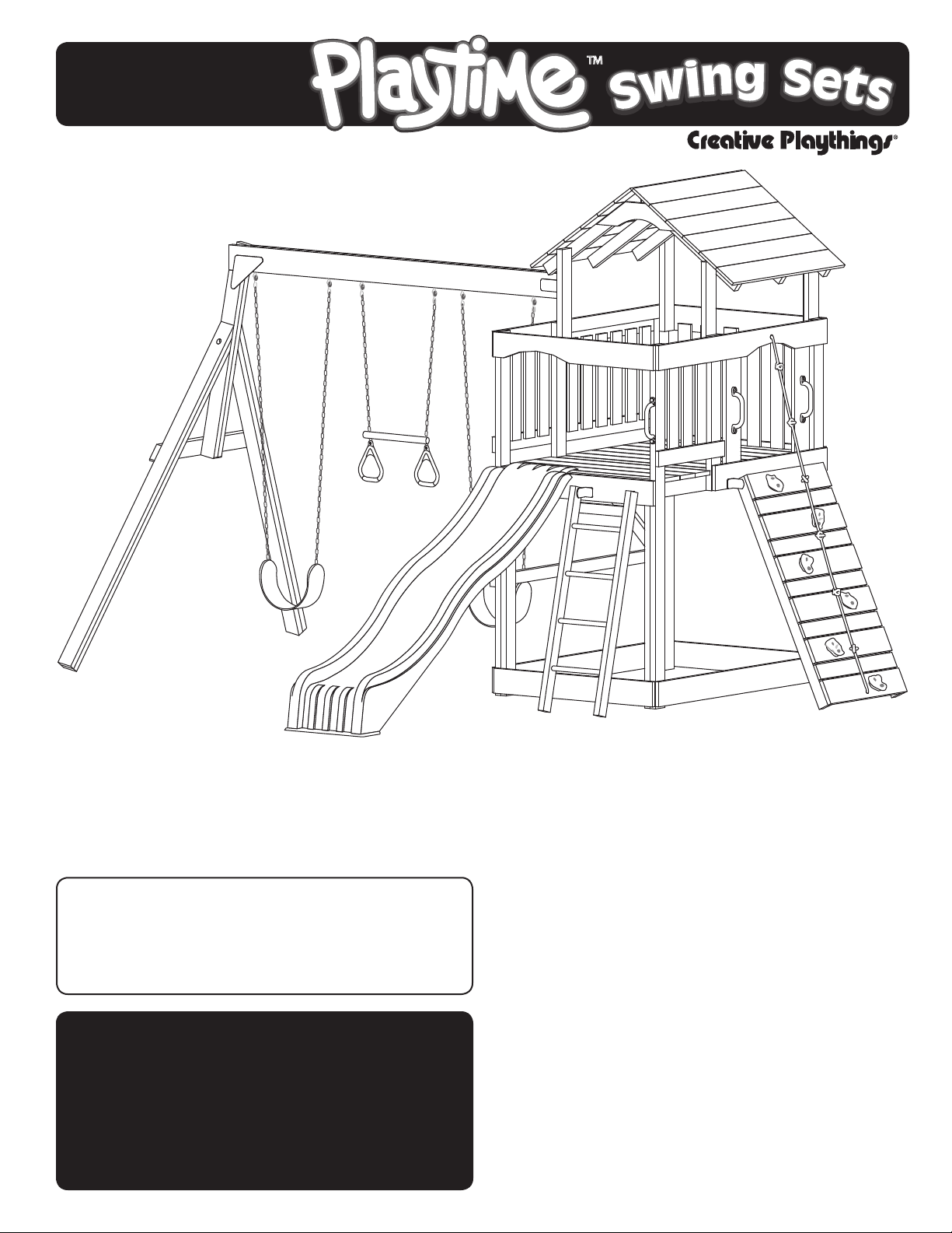
MODEL PS18EAS
ASSEMBLY MANUAL
™
By
If you have problems or questions about your Creative Playthings play set,
DO NOT CALL THE RETAILER.
Contact Creative Playthings Customer Service at 1-800-598-4997 or
All hardware on this set is specially coated
for corrosion resistance.
If non-Creative Playthings hardware is used,
it must be galvanized or stainless steel.
This product is intended for single
family home/residential use only and
not intended for use in any public
setting. Placement in any public
setting constitutes a misuse of this
product.
Please read the owner’s manual before the
assembly of your Play Set. it provides additional
information on the care and use of your Play Set.
You must carefully read the entire instruction man
ual before proceeding with the assembly or use
of your new Play Set.
Creative Playthings takes great care to design its
products with your child’s safety in mind. How
ever, only with careful supervision and proper
safety instructions, can you be assured of safe
play time on any product designed for children.
Save these instructions for reference in case you
need to contact customer service.
-
-
Page 2
PLAY SET SAFETY
FOR SAFETY SAKE, PLEASE TAKE TIME TO READ ALL INSTRUCTIONS COMPLETELY AND
CAUTION YOUR CHILDREN APPROPRIATELY.
Observing the following statements & warnings reduces the likelihood of serious or fatal injury:
• Children should use equipment only in its intended manner.
• Children should not wear loose or stringed clothing while using playground equipment.
• Children should not play on equipment in wet weather conditions due to potentially slippery surfaces.
• Children should NOT walk too closely in front of, behind, or between moving swings and trapezes.
• Children should NOT swing empty swing seats.
• Children should NOT jump off swings and/or trapeze while they are in motion.
Children should NOT twist swing chains because this will reduce the strength of the chains.
•
• Children should sit in the center of the swings with their full weight on the seats.
• Children should NOT be on the top surface of the swing beam.
• Children should NOT use the equipment in a manner other than intended.
• Children should NOT get off the equipment while it is in motion.
• On-site adult supervision is required at all times for children of all ages.
• Until assembly is complete, DO NOT let your children use the Play Set.
• Never fasten anything not approved by Creative Playthings to your Play Set. Accessories or items not ap
proved by Creative Playthings include; Dog runs, clothes lines, electrical devices, or bird feeders etc.
• Suspended ropes, chains, and cables must be secured at both ends.
• Suspended ropes, chains, and cables must not be capable of looping back on themselves.
• Do not allow more than 120 lbs. on Single occupancy swing accessories such as the Sling Swing and Trapeze.
• Do NOT allow more than 175 lbs. on multiple use swing accessories such as the Back-to-Back Plastic Glider.
• Do NOT allow more children on the Play Set than can simultaneously use all the swing stations at one time.
• Children MUST NEVER wear bicycle helmets while playing on the play-set.
Assembly Safety:
• Adult assembly required
• Face slide away from the sun.
• Keep the work area clean and clear of obstructions.
• Children should stay out of the work area until the safe play area is cleared of obstacles, the Play Set has been
completely assembled, all hardware has been tightened and checked, and all tools have been picked up.
• Keep children off the Play Set until it has been completely assembled.
• Parts of the assembly process may require help from another competent adult.
-
• Do not stand on the platform until the Play Set has been completely assembled, use a step ladder if you can
not reach high enough.
• Follow the manufacturers' safety recommendations for the tools and equipment you use.
• Avoid assembling your Play Set in poor weather conditions.
• Wear proper clothing and safety equipment (safety glasses, boots, and gloves) while assembling your Play Set.
MODEL PS18EAS
19862-600 Rev E (01-19)
Page 2
© Copyright 2014, Creative Playthings
Page 3
SAFE PLAY AREA
SELECTING THE CORRECT LOCATION FOR YOUR PLAY PRODUCT IS IMPORTANT FOR
YOUR CHILDREN’S SAFETY AND THE PRODUCT’S LONGEVITY.
Play Set Dimensions:
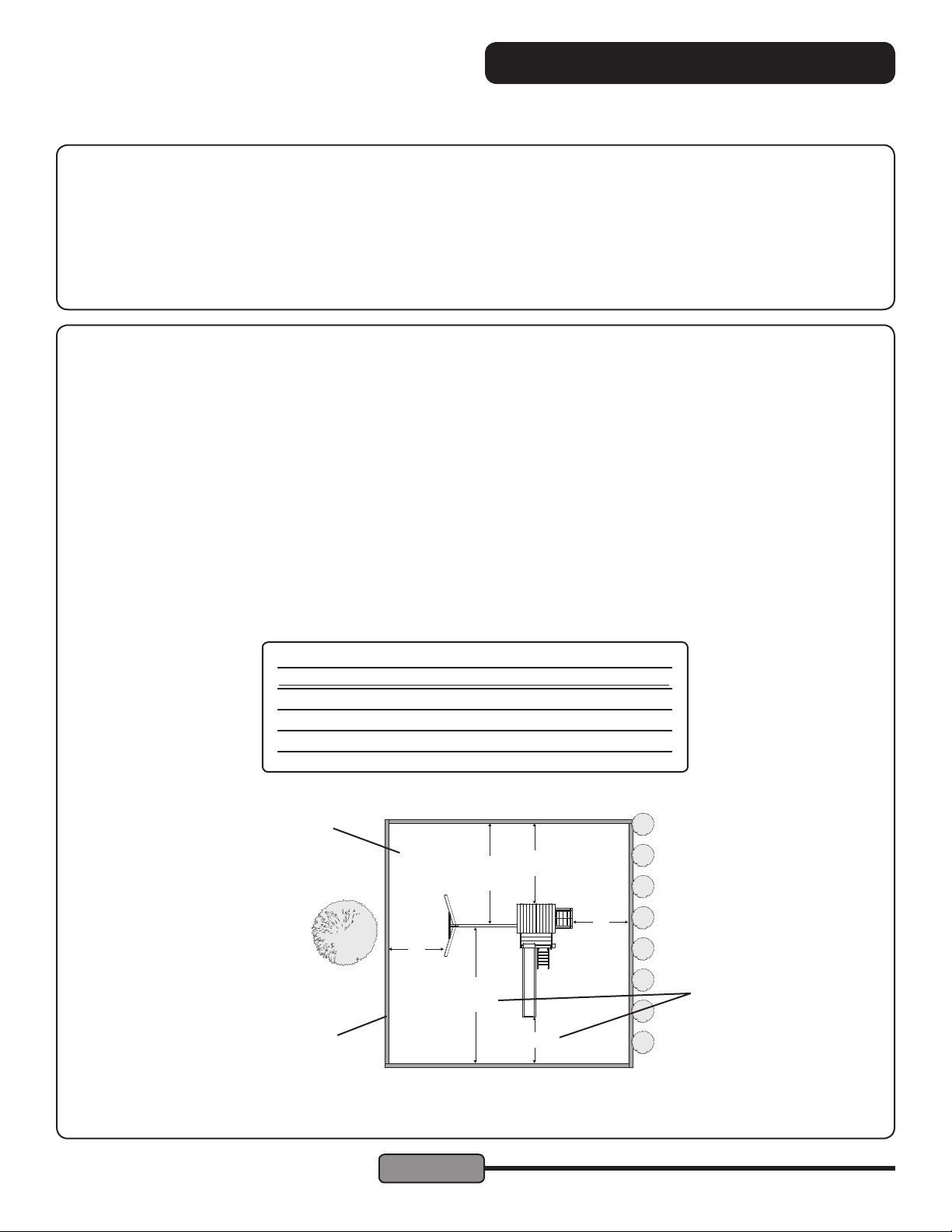
• The MODEL PS18EAS Play Set has ground dimensions of 14'-10" x 12'-4".
• The MODEL PS18EAS Play Set requires a level ground surface of 26'-10" x 29'-0" for a Safe Play Area.
• Additional accessories may increase the size of the Safe Play Area.
• The maximum fall height for your MODEL PS18EAS is 87" as measured from the top of the swing beam.
Safe Play Area:
• The Safe Play Area refers to a zone extending 6' (2 meters) beyond the Play Set on all sides, including the slide
and the space above the Play Set. Because children may deliberately jump from a moving swing, the Safe Play
Area must be extended to 14' (4.27 meters) in front of and behind a swinging Accessory.
• The ground surface must be level. Installing your Play Set on sloping ground can cause it to lean or “rack”.
This leaning puts additional stress on all connections and joints and in time will cause those connections to
loosen and fail.
• The Safe Play Area must be free of all structures, landscaping, trees and branches, rocks, wires, and other
obstacles to safe play. Children can be seriously injured running, or swinging into these obstacles.
• Remove all tripping hazards from the Safe Play Area. Tripping hazards include; roots, stumps, rocks, landscap
ing, sprinkler heads, railroad ties, plumbing and electrical connections.
• Do not install your Play Set over concrete, gravel, asphalt, packed earth, or any other hard surface. The follow
ing is a list of recommended ground covers from the Consumer Product Safety Commission.
RECOMMENDED GROUND COVER
Suggested Material Uncompressed Depth
Double Shredded Bark Mulch 9"
Uniform Wood Chips 12"
Fine Gravel 12"
Fine Sand 12"
• Any edging used to contain the ground cover must be beyond the Safe Play Area. (i.e. Landscape Timbers)
Safe play area using
recommended ground cover.
14'
(4.27 M)
6'
(2 M)
6'
(2 M)
Whichever is greater
Landscape Timbers 6' from
play structure.
6'
(2 M)
14'
(4.27 M)
6'
(2 M)
-
-
A FALL ONTO A HARD SURFACE COULD RESULT IN SERIOUS
INJURY.
© Copyright 2014, Creative Playthings
Page 3
MODEL PS18EAS
19862-600 Rev E (01-19)
Page 4
HARDWARE BAG CONTENTS
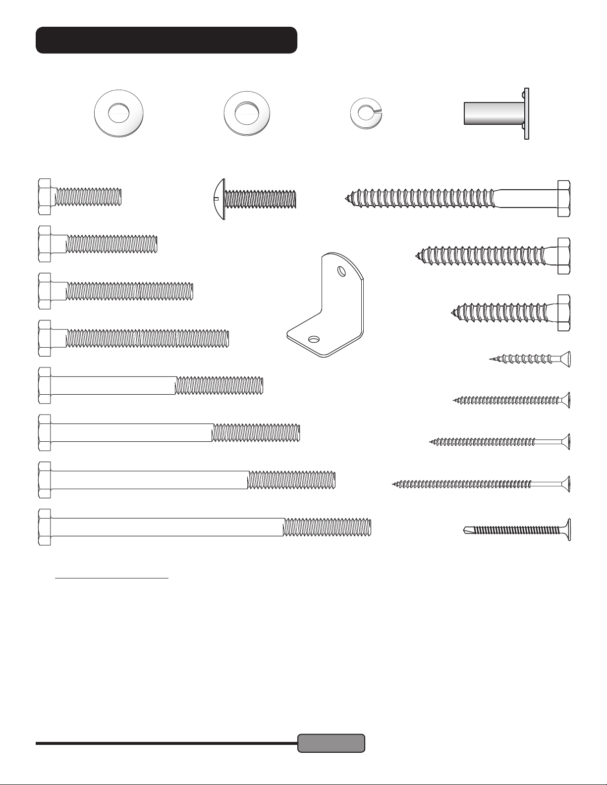
ASSEMBLY HARDWARE:
Illustrations are representative of hardware.
Slight variation of appearance may occur.
1/4" Flat Washer 8mm Flat
1/4 x 1" Hex Bolt
1/4 x 1" Truss Head Bolt
1/4 x 1-1/2" Hex Bolt
1/4 x 2" Hex Bolt
1/4 x 2-1/2" Hex Bolt
1/4 x 3" Hex Bolt
Washer
1/4" Lock
Washer
Access. Bracket
(Not to Scale)
1/4" Weld
Nut
1/4 x 3" Lag Screw
1/4 x 2" Lag Screw
1/4 x 1-1/2" Lag Screw
#8 x 1-1/4" Screw
#8 x 1-5/8" Screw
1/4 x 3-1/2" Hex Bolt
1/4 x 4" Hex Bolt
1/4 x 4-1/2" Hex Bolt
50568-700 PT Hardware
101 17001-104 Weld Nut 1/4"
24 12002-203 Flat Washer 8MM
114 12002-205 Flat Washer 1/4"
99 12017-205 Lock Washer 1/4"
72 17025-104 Screw #8 x 1-1/4"
142 17025-106 Screw #8 x 1-5/8"
36 17025-112 Screw #8 x 2"
8 17025-109 Screw #8 x 2-1/2"
8 17120-502 Self-Drill Screw #10 x 1-1/2"
8 17003-409 Hex Bolt 1/4 x 1"
28 17003-609 Hex Bolt 1/4 x 1-1/2"
15 17003-809 Hex Bolt 1/4 x 2"
MODEL PS18EAS
19862-600 Rev E (01-19)
#8 x 2" Screw
#8 x 2-1/2" Screw
#10 x 1-1/2" Self-Drill Screw
14 17003-1209 Hex Bolt 1/4 x 3"
18 17003-1409 Hex Bolt 1/4 x 3-1/2"
12 17003-1609 Hex Bolt 1/4 x 4"
4 17003-1809 Hex Bolt 1/4 x 4-1/2"
2 17119-409 Truss Head Bolt 1/4 x 1"
2 17036-601 Lag Screw 1/4 x 1-1/2"
29 17036-801 Lag Screw 1/4 x 2"
8 17036-1201 Lag Screw 1/4 x 3"
4 14161-400 Access Bracket, Green
More hardware is included than is required for assembly.
Page 4
© Copyright 2014, Creative Playthings
Page 5
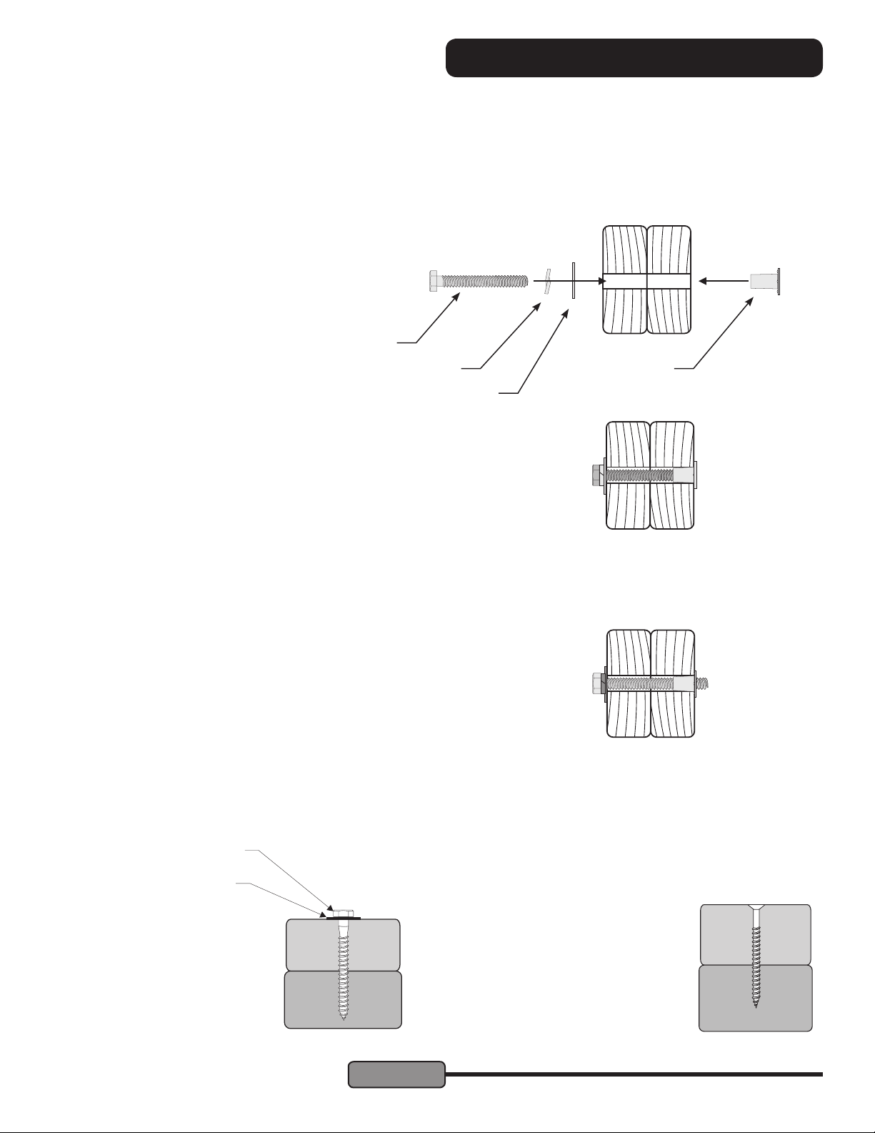
PRE ASSEMBLY INFORMATION
CREATIVE PLAYTHINGS Play SetS USE A FEW STANDARD CONNECTIONS. BECOMING
FAMILIAR WITH THESE CONNECTIONS WILL SIMPLIFY ASSEMBLY AND INSURE A
SAFER PLAY PRODUCT FOR YOUR CHILDREN.
Hex Bolt & Weld Nut Assembly Procedure:
Assembly Layout:
Align the holes in the parts to be fastened. Start
preliminary tightening of bolt into weld nut by
hand. Tighten each bolt with a wrench until the
lock washer is fully compressed between the
head of the bolt and the at washer.
Hex Bolt
Correct Assembly:
Bolt has been screwed securely into weld nut
and the connection is tight. Check connections periodically for tightness during the life
of the Play Set . Do not over tighten.
Incorrect Assembly:
If during assembly or maintenance the bolt pro-
trudes 1/8" past the weld nut, use additional at
washers, call customer service or replace the
bolt at a local hardware store. You may be overtightening or using the wrong size bolt.
Failure to replace this bolt with a shorter one
could result in serious injury.
Lock Washer
Flat Washer
Weld Nut
Typical Installation - Lag Screws:
Lag Screw
Flat Washer
• Pilot drill with the appropriate
diameter drill bit and then use
a socket to tighten.
• DO NOT over tighten
© Copyright 2014, Creative Playthings
Page 5
Typical Installation - Wood Screws:
• Use an electric drill or screw gun to drive screws.
• Drill 1/8" pilot holes where required.
• We recommend that you lubricate the
threads of the screws with beeswax or
soap to ease installation and minimize
breaking screws.
• It is very important to make cer-
tain that the tops of all screws are
ush with the surface of the wood
and there are no protruding sharp
edges.
MODEL PS18EAS
19862-600 Rev E (01-19)
Page 6
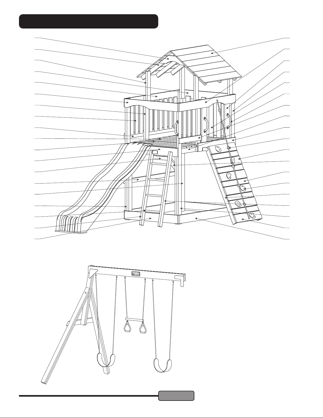
PLAY SET VIEW
AI
AK
AH
AF
X
V
F
C
K
S
N
L
T
I
AT
AL
P
AJ
AB
Z
AQ
Y
G
W
AR
O
A
R
AS
AA
AC
AP
AM
AE
Items Packaged Separately:
M
AN
AD
Q
J
60081-102 Playtime Swing Beam
AA934-204 2 Swings, 1 Trapeze*
(2 Sling Swings & 1 Ring Trapeze)
8515-202 8 Ft. Wave Slide, Green
*Alternative swing features may
be included with your set. Use the
instructions packed with the swing
equipment for assembly.
MODEL PS18EAS
19862-600 Rev E (01-19)
Page 6
© Copyright 2014, Creative Playthings
Page 7
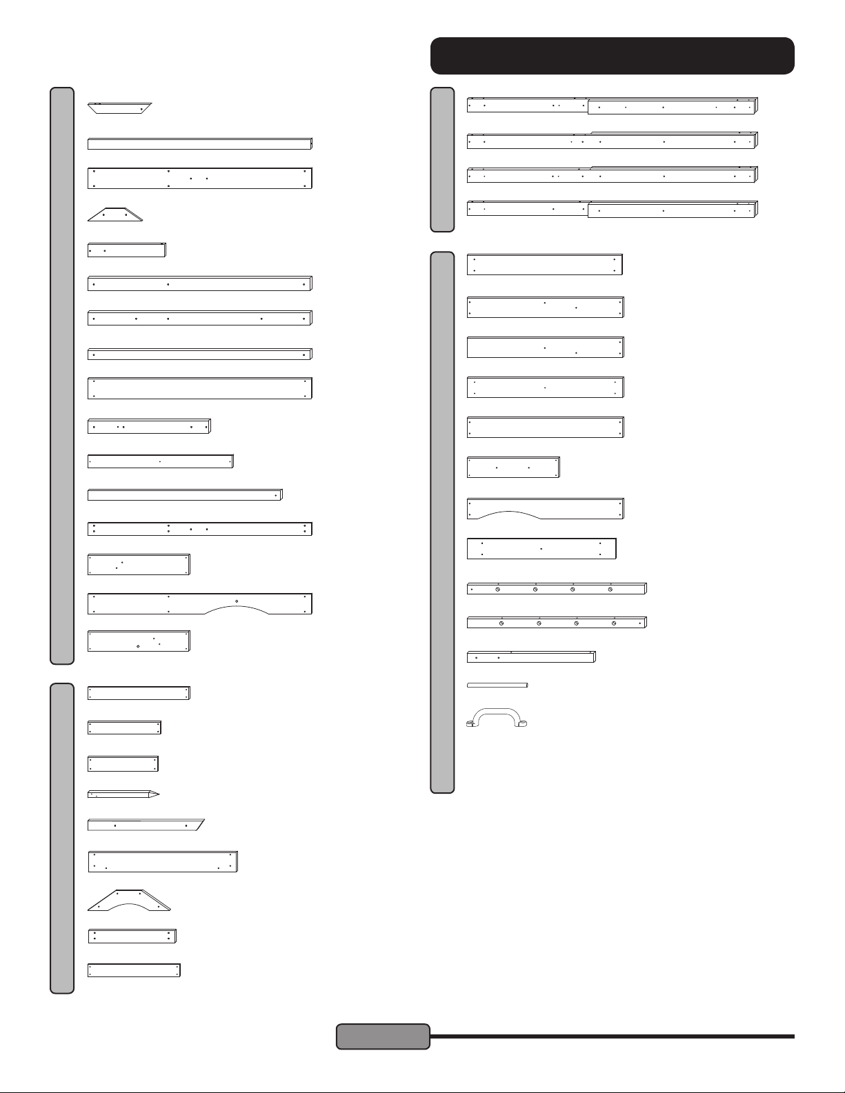
Take inventory of all parts, making sure nothing is missing or defec-
tive. If you nd that parts are missing or defective call the Creative
Playthings Customer Service Department at 1-800-598-4997.
COMPONENT VIEW
A 4 32561-102 Angle Brace 2 x 3 x 17-1/4"
B* 1 33732-102 Stringer 2 x 3 x 59-1/2"
C 1 35441-102 Left Wall Support 5/4 x 6 x 59-1/2"
D* 1 33742-102 Ceiling Joist 1 x 4 x 14-5/8"
F 4 35443-102 Roof Upright 2 x 4 x 20-3/4"
G 1 33760-102 Platform Right 2 x 4 x 59-3/8"
H* 1 33761-102 Platform Left 2 x 4 x 59-3/8"
I 1 33924-102 Safety Rail 2 x 3 x 59-3/8"
J 2 33950-102 Sandbox Side 5/4 x 6 x 59-1/2"
K 2 33731-102 Mid Post 2 x 4 x 32-1/2"
BOX 1 - 60083-331
L 3 33954-102 Narr. Deck Board 5/4 x 4 x 38-5/8"
M 2 35499-102 Rock Upright 2 x 3 x 51-1/2"
N 1 33737-102 Lower Wall Supp. 5/4 x 4 x 59-1/2"
O 5 33920-102 Rock Board 5/4 x 6 x 27"
P 1 35442-102 Right Top Support 5/4 x 6 x 59-1/2"
AA 1 40573-102 Post, Back Left
AB 1 40574-102 Post, Back Right
AC 1 40575-102 Post, Front Left
BOX 2 (CONT'D)
AD 1 40576-102 Post, Front Right
AE 2 33949-102 Sandbox End 5/4 x 6 x 41-1/4"
AF 1 33951-102 Platform Front 5/4 x 6 x 41-1/2"
AG* 1 33952-102 Platform Back 5/4 x 6 x 41-1/2"
AH 9 33953-102 Deck Board 5/4 x 6 x 41-1/2"
AI 1 33955-102 End Support 5/4 x 6 x 41-1/2"
AJ 2 33963-102 Entrance Slat 5/4 x 6 x 24-1/2"
AK 1 33968-102 Front Arch 5/4 x 6 x 41-1/2"
AL 12 33745-402 Roof Board 1 x 6 x 39-1/2"
BOX 3 - 60083-333
AM 1 33702-102 Ladder Rail Left 2 x 3 x 47-1/2"
AN 1 33703-102 Ladder Rail Right 2 x 3 x 47-1/2"
Q 1 35440-102 Rock & Rope Board 5/4 x 6 x 27"
R 5 33921-102 Spacer Board 1 x 4 x 27"
S 12 33741-102 Short Wall Slat 1 x 4 x 19-1/2"
T 1 33972-102 Ladder Slat 1 x 4 x 15-3/4"
U* 5 36515-102 Ground Stake
V 6 33744-102 Rafter 2 x 3 x 31"
W 1 33922-102 Rock Wall Mount 5/4 x 6 x 39-1/2"
BOX 2 - 60083-332
X 2 33956-102 End Joist 5/4 x 6 x 22"
Y 1 33739-102 Short Wall Supp. 5/4 x 4 x 23-1/4"
Z 6 33962-102 Narrow Wall Slat 1 x 4 x 24-1/2"
© Copyright 2014, Creative Playthings
Page 7
AO 2 33923-102 Swing Mount 2 x 3 x 34"
AP 4 14202-400 Ø1" x 15" Rung, Green
AQ 3 15034-100 Hand Grips
AR 1 18008-138 Climbing Rope
AS 1 50428-400 Climbing Rocks (6)
1 50539-800 PT Hardware Bag
1 50469-100 Playtime Nameplate Pack
AT 1 8515-202 8 Ft. Wave Slide, Green
* Not marked on Play Set View page.
MODEL PS18EAS
19862-600 Rev E (01-19)
Page 8
MAINTENANCE INSTRUCTIONS
YOUR CREATIVE PLAYTHINGS Play Set IS STAINED AT OUR FACTORY.
STAINING IS NOT NEEDED AT THE TIME OF INITIAL ASSEMBLY.
Re-staining Information:
• Pigmented, exterior, water repellent stains are recommended and will provide an excellent barrier against moisture
without hiding the natural wood grain or leaving a lm that may later crack or peel.
• We recommend that you apply stain according to the instructions and precautions recommended by the stain manufacturer.
• It should take three or more quarts to cover your set.
• Contact your local dealer or call Creative Playthings for our staining products.
• All rungs are pre-nished at the factory and do not require any nishing at the time of initial assembly.
• Do not paint, or varnish rungs or steps.
• Avoid using nishes that create slippery surfaces.
Maintenance:
• Wooden playground equipment will last for years with proper maintenance. Maintenance of the Play Set nish will vary
depending on weather and climate.
• As a safety precaution, check all hardware, such as nuts and bolts, for tightness twice a month during use and at the
beginning of each play season. Tighten as required and specied in these instructions. Do not over-tighten.
• Check structure twice monthly during usage for any evidence of deterioration. If upon inspection, hardware has sharp edges,
rusted or structural pieces have signs of premature failure; replace them through Creative Playthings Customer Service.
• Oil all metallic moving parts monthly during the usage season.
• The swings, trapeze, tent, rope ladders, and any other removable plastic accessories should be removed and taken
indoors when outside temperatures drop below 32° F (0° C).
• Wood will expand and contract as it adjusts to temperature changes and varying moisture conditions. Checks or cracks
are a natural characteristic of all wood and will not affect the strength or durability of the wooden components.
• To maintain the nish of your set, a light sanding and an application of an exterior stain will repair scratches and prevent
wood from aging prematurely.
• Finishes applied to ladder rungs must not create a slippery surface. Never varnish.
• The wood parts of your Play Set should never be disposed of by burning.
• Dispose of all parts so as not to create a hazard.
• "Check all coverings for bolts and sharp edges and replace when required."
• "Check swing seats, chains, ropes, and other means of of attachments for evidence of deterioration". Replace through
Creative Playthings Customer Service.
• Twice a month during play season rake and check depth of loose ll protective surfacing materials to prevent compaction and to maintain appropriate depth. Replace as necessary.
Tools & Materials Suggested for Finishing & Assembly:
• Claw Hammer
• Carpenter’s Level
• Box Wrench or Sockets (7/16" & 1/2")
• Electric Drill
• 1/8", 3/16", 5/16" diameter Drill Bits
MODEL PS18EAS
19862-600 Rev E (01-19)
• Screwdriver or driver drill (Medium Phillips)
• Locking Pliers
• 10 ft. Tape Measure
• Framing Square
• 6 ft. Step Ladder
Page 8
© Copyright 2014, Creative Playthings
Page 9
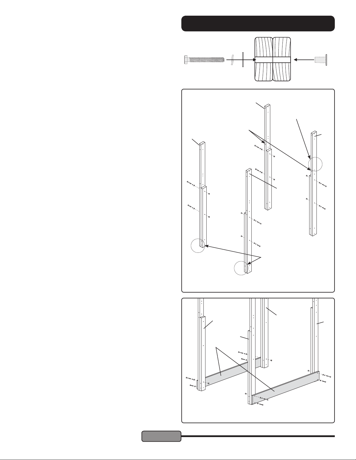
Hex Bolt Assembly:
Throughout this guide a Hex Bolt Assembly consists of
one Hex Bolt, one Lock Washer, one Flat Washer and one
Weld Nut. Long Weld Nuts are used unless otherwise noted.
STEP 1 — Assemble Posts:
Locate Back Left Post (AA), Back Right Post (AB), Front Left
Post (AC), and Front Right Post (AD).
Secure each post using two 1/4 x 3" Hex Bolt Assemblies
through the two central holes as shown at right. If the tip of
the Hex Bolt protrudes, add another Flat Washer next to the
rst.
Hint: The posts can be difcult to tell apart. There are three
clues at right.
1) The holes for the Platform Ends are higher on the back
Posts.
2) There are no holes for a Lower Wall Support on the Back
Right Post.
3) Look at the holes on the narrow edge of the post to tell the
Left Front Post from the Right Front Post.
AC
ASSEMBLY INSTRUCTIONS
AA
2) No holes here
on Back Right Post
1) These holes are
higher on back posts.
AB
AD
STEP 2 — Sandbox Sides:
Fasten one Sandbox Side (J) to the Front Left Post and Back
Left Post using 1/4 x 3-1/2" Hex Bolt Assemblies through the
top holes and 1/4 x 2" Lag Screws and Flat Washers through
the bottom holes.
Repeat the process with the other Sandbox Side and right
posts.
Note: Additional help is suggested for
steps 2 through 6 to support the Corner
Posts.
View from the
front of the set.
AC
J
1/4 x 3-1/2" Hex Bolts in
top holes, 1/4 x 2" Lag
Screws in bottom holes.
3) These holes face
opposite on the left
& right front posts
AA
AB
AD
© Copyright 2014, Creative Playthings
Page 9
MODEL PS18EAS
19862-600 Rev E (01-19)
Page 10
ASSEMBLY INSTRUCTIONS
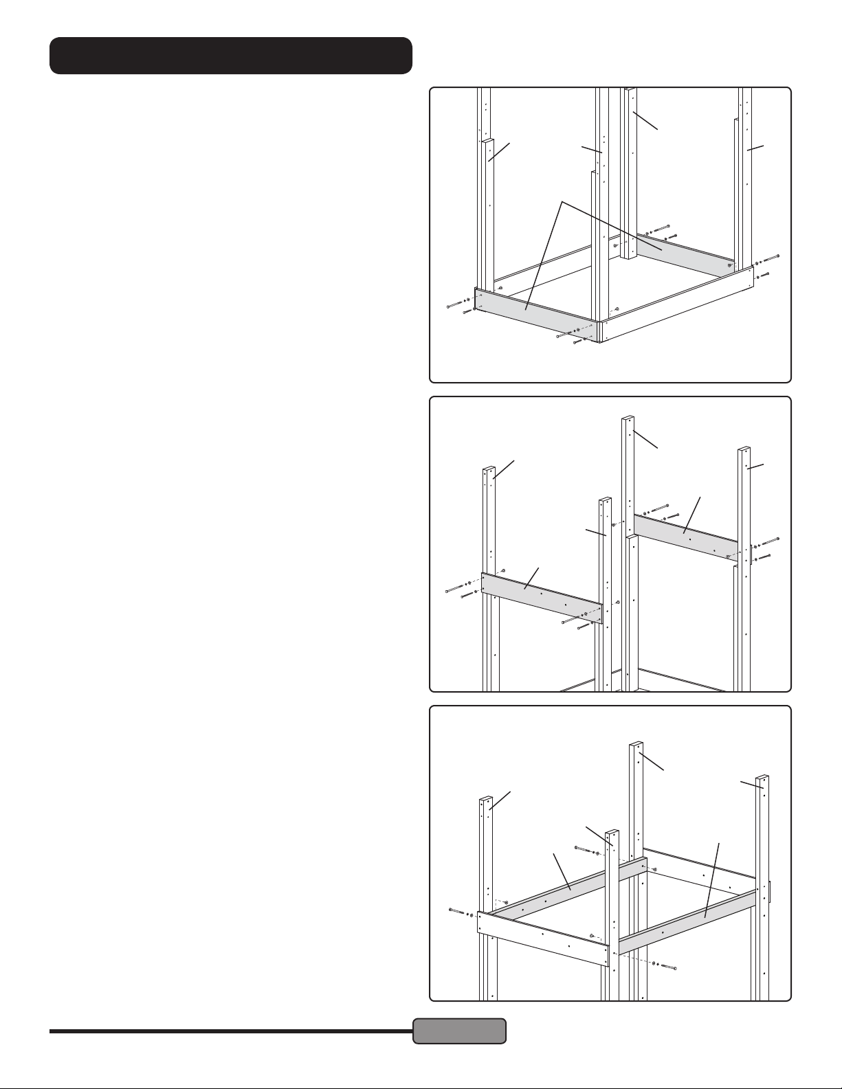
STEP 3 — Sandbox Ends:
Fasten one Sandbox End (AE) to the front of the Front Left
and Front Right Posts as shown at right. Use 1/4 x 4" Hex Bolt
Assemblies in the top holes and 1/4" x 2" Lag Screws with
1/4" Flat Washers in the bottom holes.
Fasten the other Sandbox End (AE) to the back of the Back
Left and Back Right Posts in the same way.
Note: Additional help is suggested for
steps 2 through 6 to support the Corner
Posts.
2" Lag Screw in
Bottom Holes
AC
AE
AD
AA
AB
4" Hex Bolt
Assembly in top
holes
STEP 4 — Platform Ends:
Fasten the Platform Front (AF) to the Front Left and Front Right
Posts as shown at right. Use 1/4 x 4" Hex Bolt Assemblies in
the top holes and 1/4" x 2" Lag Screws with 1/4" Flat Washers
in the bottom holes.
Fasten the Platform Back (AG) to the middle post assemblies
in the same way.
STEP 5 — Platform Sides:
Fasten the Platform Left (H) to the left posts in the orientation shown using two 1/4 x 3" Hex Bolt Assemblies.
Fasten the Platform Right (G) to the Front Right Post in the
orientation shown using one 1/4 x 3" Hex Bolt Assembly.
Rest the other end of the Platform Right in place to be fastened in the following step.
4" Hex Bolt
Assembly in top
holes
Three 1/4 x 3" Hex
Bolt Assemblies
AC
AD
AF
2" Lag Screw in
Bottom Holes
AC
AD
H
AA
AA
AB
AG
AB
G
MODEL PS18EAS
19862-600 Rev E (01-19)
Page 10
© Copyright 2014, Creative Playthings
Page 11
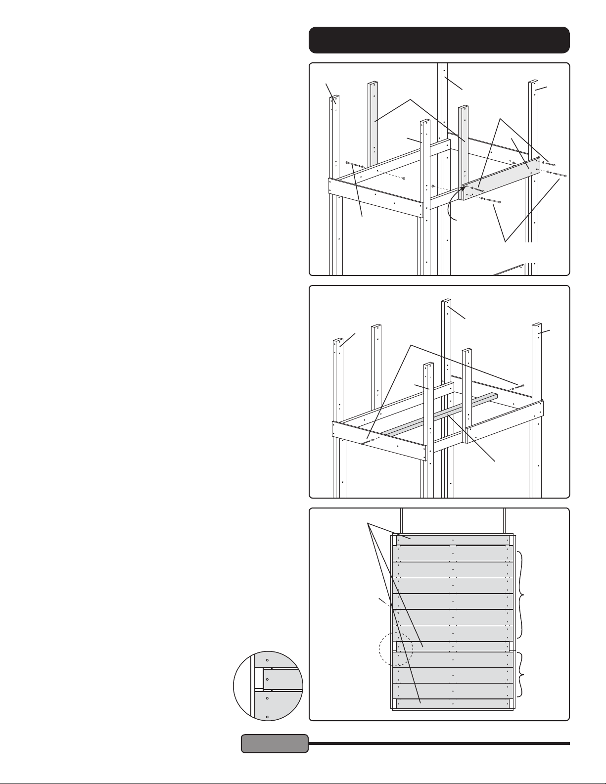
STEP 6 — Mid Posts & Rock Wall Mount:
Align one Mid Post (K) as shown. Fasten it to the Platform
Left using one 1/4 x 3" Hex Bolt Assembly.
Fasten the Rock Wall Mount (W) to the Back Right Post and
the Platform Right using one 1/4 x 3-1/2" Hex Bolt Assembly
in the lower right hole.
Fasten the other end of the Rock Wall Mount to the right Mid
Post (K) and the Platform Right using one 1/4 x 3-1/2" Hex
Bolt Assembly in the lower left hole.
Fasten one 1/4 x 2" Lag Screw and Flat Washer through the
top right hole of the Top Rope Support and into the Back
Right Post
Use a level to assure that the right Mid Post is plumb. Drill
a 3/16" diameter pilot hole 1-1/4" into the right Mid Post
through the top right hole in the Rock Wall Mount. Secure
using one 1/4 x 2" Lag Screw and Flat Washer.
STEP 7 — Stringer:
Fasten the Stringer (B) to the Platform Front and Platform
Back using two 1/4 x 3" Lag Screws and Flat Washers as
shown.
AC
ASSEMBLY INSTRUCTIONS
AA
2" Lag
Screw
W
3/16"
pilot drill
3-1/2" Hex Bolt
Assembly
AA
3" Hex Bolt
Assembly
AC
K
AD
3" Lag
Screw
AB
AB
STEP 8 — Deck Boards:
Locate the nine Deck Boards (AH) and three Narrow Deck
Boards (L) and lay them across the platform supports and
Stringer in the arrangement shown at right. Align the ends of
the Deck Boards; the Narrow Deck Boards t between the
uprights.
Starting at the front of the gym fasten each board using #8 x
1-5/8" Screws. For the rst four boards, leave a gap of 1/8"
or less to limit the possibility of clothing being snagged when
children use the slide. Space the rest of the boards evenly.
Note that the Narrow Deck Board between the Mid Posts
need not align exactly with the Mid Posts.
L
Evenly space the
back eight boards
< 1/8" gap between
1st four boards
AD
B
#8 x 1-5/8"
Screws
AH
AH
© Copyright 2014, Creative Playthings
Page 11
MODEL PS18EAS
19862-600 Rev E (01-19)
Page 12
ASSEMBLY INSTRUCTIONS
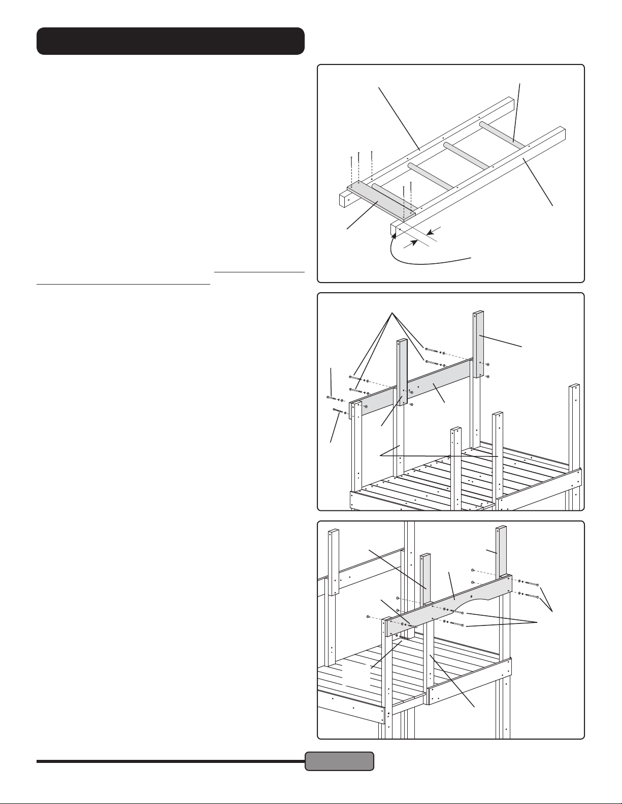
STEP 9 — Access Ladder Rungs & Slat:
Fit four 15" Rungs (AP) into the holes in the Left Ladder Rail
(AM) and the Right Ladder Rail (AN). Set the assembly at
on a solid surface. Make sure that the rungs are completely
inserted with the ends of the rungs snug against the bottom
of the holes.
Use #10 x 1-1/2" Self-Drilling Screws, through the holes
provided, to fasten the rungs in place. (The Self-Drilling
Screws have a drill-bit tip. Point the screw toward the center
of rung diameter and press rmly. Do not sink the head of the
screw beyond ush with the surface of the wood.
Use four #8 x 2" Screws to fasten the Ladder Slat (T) to the
Ladder Rails. The top edge of the Ladder Slat should be
about 2-1/4" below the top of the Ladder Rails as shown.
Make sure the gap between the top Rung and the Ladder slat
is less than 3-1/2"; adjust if necessary. Use a 1/8" diameter
pilot drill to make holes for the Screws.
STEP 10 — Left Wall Support & Roof Uprights:
Before this step, check the top two holes in the Mid
Posts (K). If a 1/4" bolt will not t through the holes,
make them bigger using a 5/16" drill.
Orient the Left Wall Support (C) as shown at right. Fasten
the Left Wall Support to the Left Front Post using a 1/4 x 2"
Hex Bolt Assembly though the top hole and a 1/4 x 2" Lag
Screw with Flat Washer in the bottom hole.
Fasten the Left Wall Support to the left Mid Post and one
Roof Upright (F) using two 1/4 x 3-1/2" Hex Bolt Assemblies
as shown.
Fasten the Left Wall Support to the Back Left Post and one
Roof Upright (F) using two 1/4 x 3-1/2" Hex Bolt Assemblies
as shown.
T
3-1/2" Hex Bolts
2" Hex
Bolt
2" Lag
Screw
AM
AP
AN
2-1/4"
The top of the ladder is
the end with holes in the
rails for brackets
F
C
F
K
STEP 11 — Right Wall Support & Roof Uprights:
As with the previous step. Check the top holes in the
Mid Post (K).
Secure the Right Wall Support (P) to the Front Right Post,
then the Mid Post and Roof Upright (F), then the Back Left
Post and Roof Upright as in the previous step.
MODEL PS18EAS
19862-600 Rev E (01-19)
2" Lag
Screw
Page 12
F
2" Hex
Bolt
F
P
3-1/2" Hex
Bolts
K
© Copyright 2014, Creative Playthings
Page 13
ASSEMBLY INSTRUCTIONS
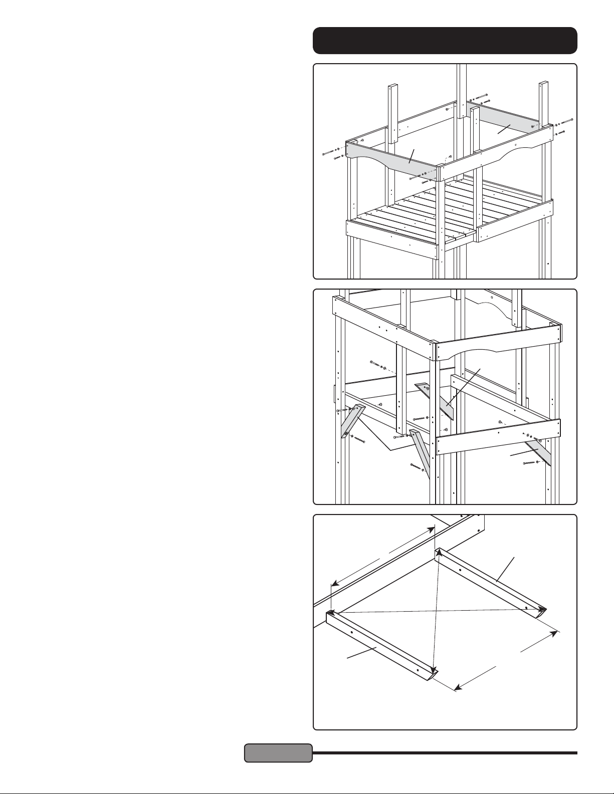
STEP 12 — Front Arch & Back End Support:
Fasten the Front Arch (AK) to the Front Left and Front Right
Posts as shown at right. Use 1/4 x 4" Hex Bolt Assemblies in
the top holes and 1/4" x 2" Lag Screws with 1/4" Flat Washers
in the bottom holes.
Fasten the End Support (AI) to the Back Left and Back Right
Posts as shown. Use 1/4 x 4" Hex Bolt Assemblies in the top
holes and 1/4" x 2" Lag Screws with 1/4" Flat Washers in the
bottom holes.
STEP 13 — Angle Braces:
Ensure the structure is in the place it will be used. Make
any needed ground adjustments before proceeding.
Use a level to determine that all horizontals are level and
posts are plumb.
Fasten two Angle Braces (A) to the Platform Left using two
1/4 x 2-1/2" Hex Bolt Assemblies as shown. Fasten the
bottom of the braces to the lookout posts using 1/4 x 3" Lag
Screws with Flat Washers. Be sure to drill 3/16" diameter
pilot holes in the posts before using the Lag Screws.
Fasten two Angle Braces (A) to the front and back of the
lower platform using two 1/4 x 2" Hex Bolt Assemblies as
shown. Fasten the bottom of the braces to the lookout posts
using 1/4 x 3" Lag Screws with Flat Washers. Be sure to drill
3/16" diameter pilot holes before using the Lag Screws.
4" Hex Bolt
Assembly in top
holes
2" Lag Screw in
bottom holes
AK
A
AI
A
A
STEP 14 — Assemble Roof Panels:
Assembly of the Roof Panels will be easiest on a work table
or other at surface.
Lay Out Roof Rafters:
Butt the square-cut end of two Rafters (V) against a straight
at surface. Align the Rafters so they are parallel and the
ends aligned and square. The distance between the Rafters
should be 30". Measure from corner to corner both ways.
When the two diagonal measurements are the same, the
rafters are square.
© Copyright 2014, Creative Playthings
Page 13
30"
V
19862-600 Rev E (01-19)
V
30"
MODEL PS18EAS
Page 14
ASSEMBLY INSTRUCTIONS
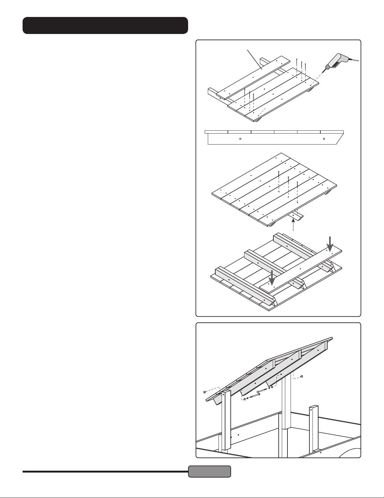
Fasten Roof Boards:
Start at the angled end of the Roof Rafters. Rest one Roof
Board (AL) on top of the Rafters ush to the angled end. Use
a 1/8" diameter drill to make pilot holes before fastening the
Roof Board to the Rafter using four #8 x 1-5/8" Screws. Drill
and screw the rst hole at an angle, as shown, to avoid the
angled cut of the rafter.
Continue with the next three Roof Boards, setting each
against the previous Roof Board and fastening them. Once
the position of the Rafters is stable, lay the rest of the Roof
Boards in place. The sixth Roof Board should overhang the
end of the Rafters by approximately 1/2". If the overhang
is less than 1/2", evenly space the Roof Boards to achieve
an overhang. If the overhang is greater, alternative holes
should be made in the nal Roof Board. Fasten the Roof
Boards using #8 x 2" Screws.
Center Roof Rafter:
Find the center of the Roof Panel Assembly, halfway between the Rafters. Align the a Roof Rafter (V) to the center
of the Roof Panel and fasten it in place using 1/8" pilot holes
and #8 x 1-5/8" Screws as with the other Rafters.
AL
Assemble Second Roof Panel:
Flip the rst Roof Panel to use it as a template to assemble
the remaining Roof Panel. Place the remaining Rafters tight
against the Rafters on the assembled panel. Align the ends.
Fasten Roof Boards to the Roof Rafters using 1/8" diam-
eter pilot holes and #8 x 1-5/8" Screws as with the rst Roof
Panel.
STEP 15 — Roof Panels to Roof Uprights:
Fasten one Roof Panel assembly to the left Roof Uprights
using 1/4 x 4-1/2" Hex Bolt Assemblies.
Repeat with the other Roof Panel on the right uprights. Rest
the angled ends Roof Panels against each other.
1/4 x 4-1/2"
Hex Bolt
MODEL PS18EAS
19862-600 Rev E (01-19)
Page 14
© Copyright 2014, Creative Playthings
Page 15
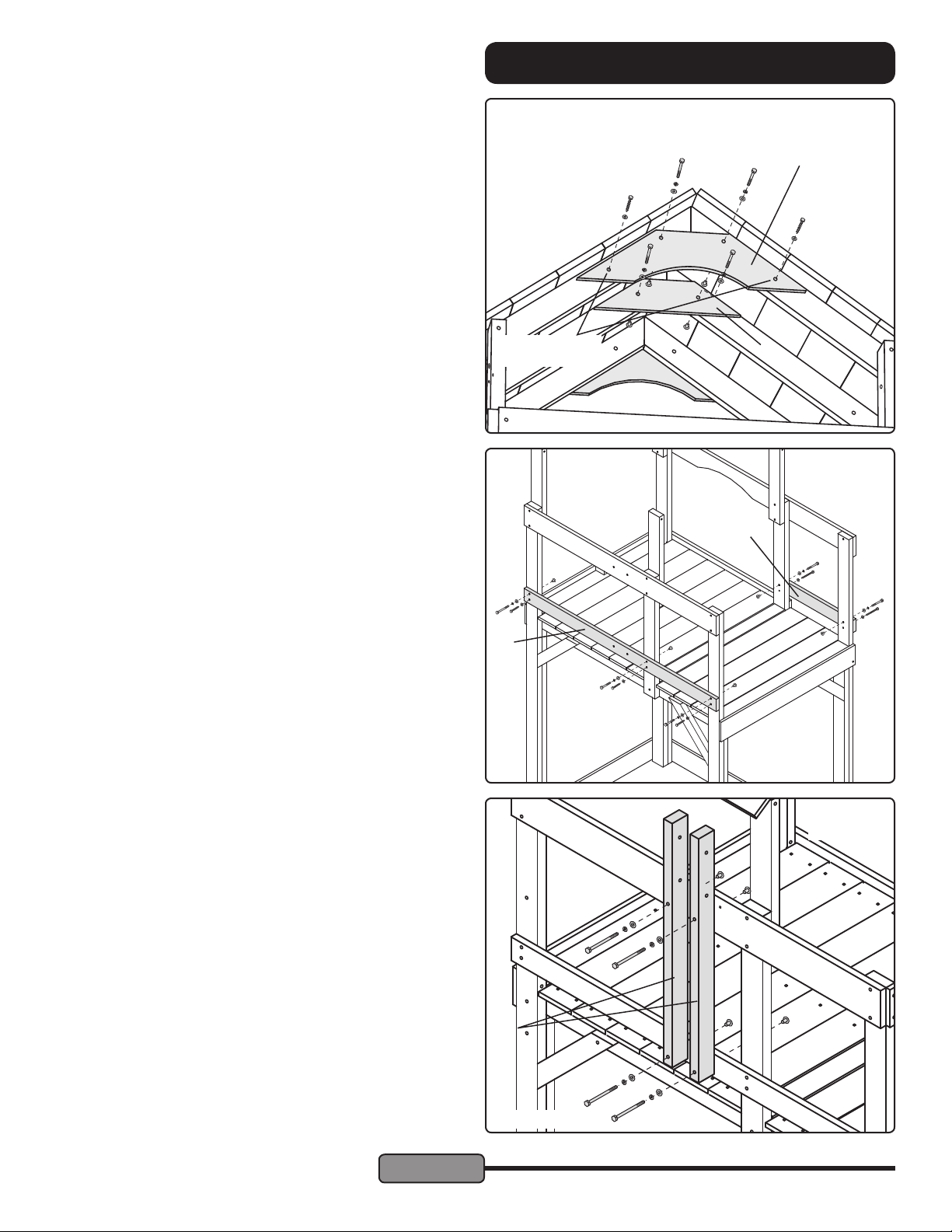
STEP 16 — Ceiling Joists:
Adjust the Roof Panels so that the angled ends are even
with each other. Fasten an End Joist (X) to the outside of the
Rafters on each end. Use two 1/4 x 2" Hex Bolt Assemblies
through the upper holes of each End Joist.
Fasten the Ceiling Joist (D) to the center Rafters using two
1/4 x 2" Hex Bolt Assemblies.
Adjust the Roof so it looks even. Adjust the End Rafters to
look straight and centered in place. Use a 3/16" diameter drill
to make pilot holes in the Rafters through the lower holes in
the End Rafters. Secure the End Joists to the Rafters using
1/4 x 2" Lag Screws and Flat Washers through the bottom
holes.
STEP 17 — Lower and Short Wall Supports:
Fasten the Lower Wall Support (N) to the Back Left Post,
left Mid Post and Front Left Post using 1/4 x 2" Hex Bolt Assemblies through the upper holes. Secure the three lower
holes in the Lower Wall Support using 1/4 x 2" Lag Screws
and Flat Washers.
Fasten the Short Wall Support (Y) to the right Mid Post and
Front Right Post using 1/4 x 2" Hex Bolt Assemblies through
the upper holes. Secure the lower holes using 1/4 x 2" Lag
Screws and Flat Washers.
ASSEMBLY INSTRUCTIONS
Drill 3/16" diam-
eter pilot holes.
N
X
D
Y
STEP 18 — Swing Mounts:
Fasten the two Swing Mounts (AO) to the Left Wall Support
and Lower Wall Support using two 1/4 x 3-1/2" Hex Bolts
each. Be sure to orient the Swing Mounts so the holes on the
sides are near the top.
Hint: if the holes don't line-up, go back to the last step and
ip the Lower Wall Support.
© Copyright 2014, Creative Playthings
Page 15
Parts omitted
for clarity
AO
3-1/2" Hex Bolts
MODEL PS18EAS
19862-600 Rev E (01-19)
Page 16
ASSEMBLY INSTRUCTIONS
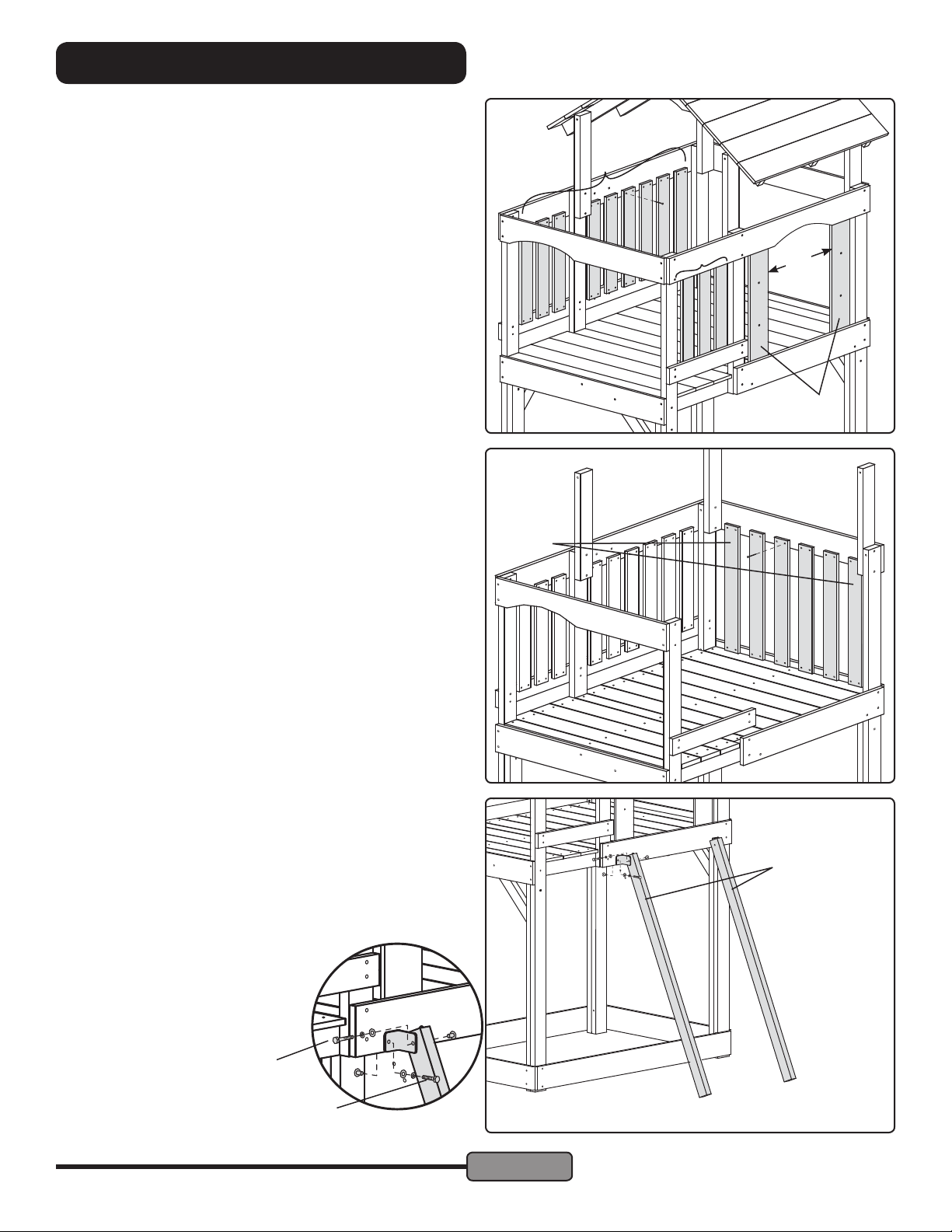
STEP 19 — Short Wall Slats & Entrance Slats:
Fasten three Short Wall Slats (S) to the Left Wall Support and
Lower Wall Support using four #8 x 1-1/4" Screws each. Evenly space the Slats between the front left post and the left Mid
Post. The gap between the Slats will be approximately 1-5/8".
Fasten six Short Wall Slats (S) to the Left Wall Support and
Lower Wall Support using four #8 x 1-1/4" Screws each. Evenly space the Slats between the back left post and the left Mid
Post. The gap between the Slats will be approximately 1-7/8".
Fasten three Short Wall Slats (S) to the Right Top Support and
Short Wall Support using four #8 x 1-1/4" Screws each. Evenly
space the Slats between the front left post and the left Mid Post.
The gap between the Slats will be approximately 1-5/8".
Fasten the Entrance Slats (AJ) to the inside of the Right Wall
Support and Rock Wall Mount using #8 x 1-5/8" Screws. Leave
a gap of 19" between the Entrance Slats.
STEP 20 — Narrow Wall Slats:
Fasten six Narrow Wall Slats (Z) to the Platform Back and End
Support using four #8 x 1-1/4" Screws each. Evenly space the
Slats between the Back Left Post and Back Right Post. The gap
between the Slats will be approximately 2-3/4".
S
S
Z
19"
AJ
STEP 21 — Climber Rails:
Fasten one Access Bracket to the top of each Climber Rail
(N) using one 1/4 x 1-1/2" Hex Bolt Assembly.
Fasten each Bracket-Rail assembly to the Rock Wall Mount
using one 1/4 x 1" Hex Bolt Assembly.
1/4 x 1-1/2" Hex Bolt
1/4 x 1" Hex Bolt
MODEL PS18EAS
19862-600 Rev E (01-19)
Page 16
Parts omitted
for clarity
N
© Copyright 2014, Creative Playthings
Page 17
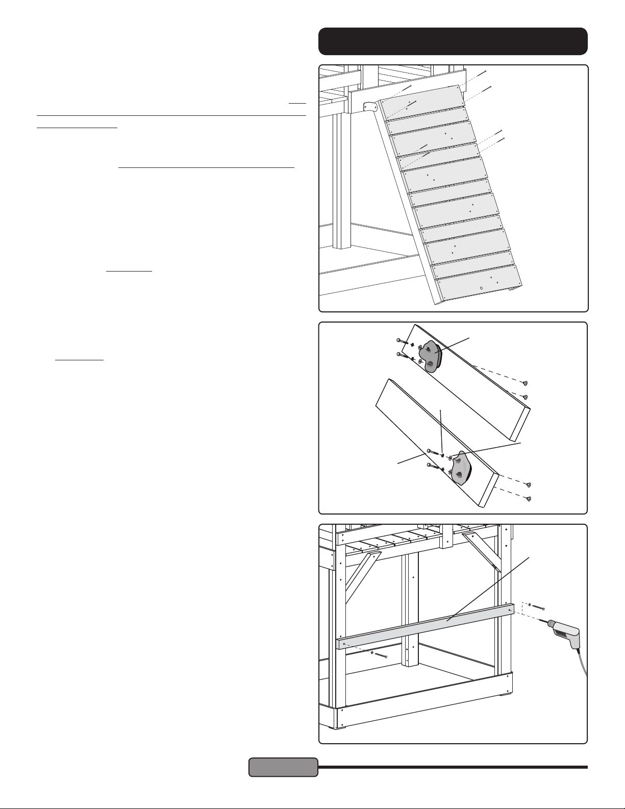
STEP 22 — Rock, Rope & Spacer Boards:
Fasten one Rock Board (O) to the top of the Climber Rails
using two #8 x 2" Screws, in the top corner holes only. Drill
1/8" diameter pilot holes for the screws to prevent splitting of
the Climber Rails.
Fasten the Rock & Rope Board (Q) to the bottom of the
Climber Rails using two #8 x 2" Screws, in the bottom corner
holes only. Use a 1/8" diameter drill to create pilot holes for
the screws to prevent splitting of the Climber Rails.
Measure the diagonal distance from the top left corner of the
Rock Board to the bottom right corner of the Rock & Rope
Board. Measure the opposite diagonal. Adjust the position
of the Climber Rails until the diagonal measurements are
equal.
Secure the Rock Board and Rock & Rope Board using #8 x
2" Screws with pilot holes.
Evenly space four Rock Boards (O) and ve Spacer Boards
(R) between the top Rock Board and Bottom Rope Board
in the pattern shown at right. The gap between boards will
be approximately 3/8". Secure each Spacer Board to the
Climber Rails using four #8 x 1-5/8" Screws. Secure each
Rock Board to the Climber Rails using four #8 x 2" Screws
with pilot holes.
ASSEMBLY INSTRUCTIONS
Use #8 x 2"
O
R
O
R
O
R
O
R
O
R
Q
AS
Screws for
Rock Boards
Use #8 x 1-5/8"
Screws for
Spacer Boards
Gaps approx.
3/8"
STEP 23 — Climbing Rocks:
Fasten one Climbing Rock (AS) to each Rock Board using
two 1/4 x 1-1/2" Hex Bolts, 1/4 Lock Washers, 8mm Flat
Washers and 1/4" Weld Nuts.
STEP 24 — Safety Rail:
Hold the Safety Rail (I) in place against the left posts, under
the Swing Mounts, approximately 23" above the ground.
Make sure no fasteners conict with the placement. Drill a
3/16" diameter pilot hole 1-1/2" deep into the post at one end
of the Safety Rail. Fasten the Safety Rail to the post using
one 1/4 x 3" Lag Screw and Flat Washer.
Swing the Safety Rail into position and make sure it is level.
Drill a pilot hole into the post at the other end of the Safety
Rail. Fasten using one 1/4 x 3" Lag Screw and Flat Washer
1/4" Lock
Washer
8mm Flat
Washer
1/4 x 1-1/2"
Hex Bolt
I
© Copyright 2014, Creative Playthings
Page 17
MODEL PS18EAS
19862-600 Rev E (01-19)
Page 18
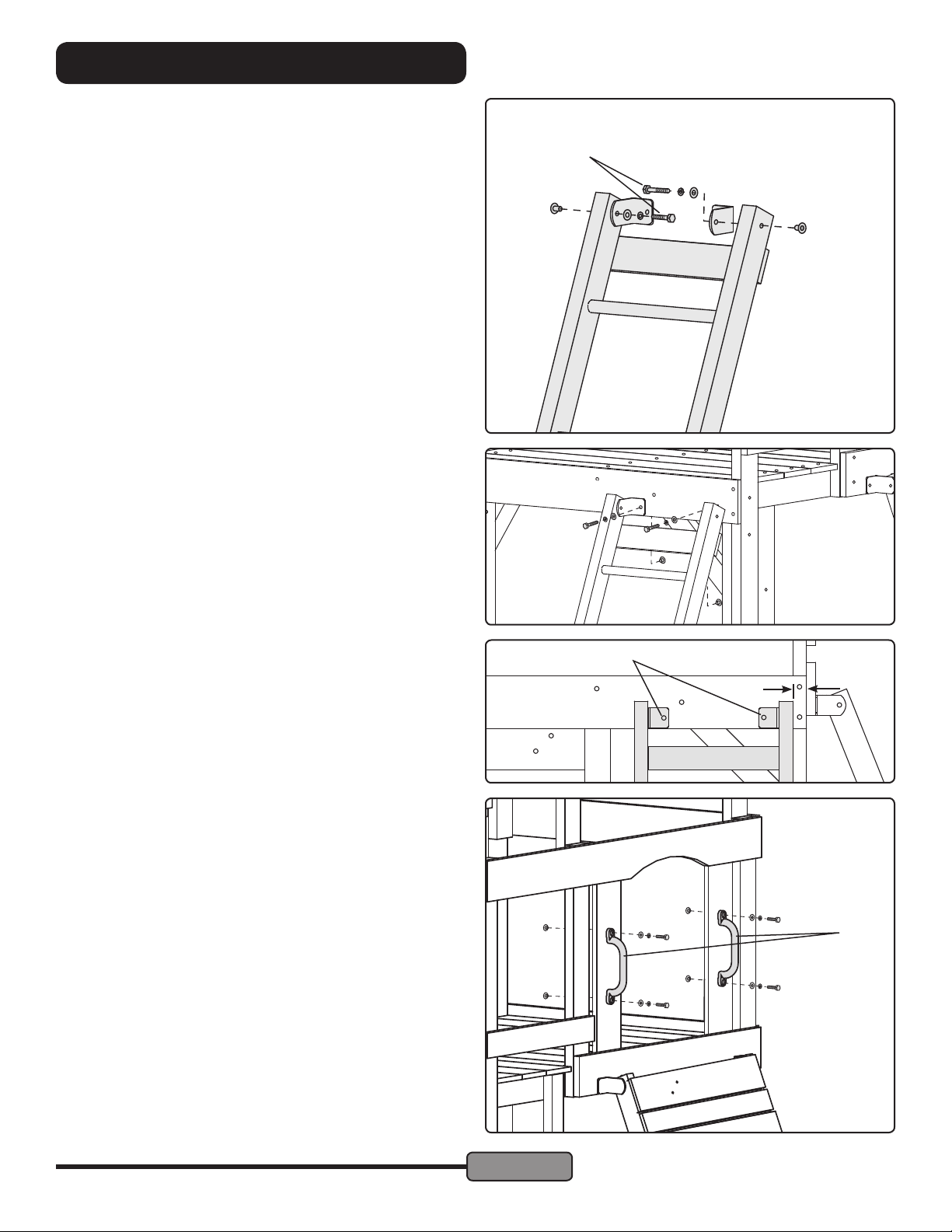
ASSEMBLY INSTRUCTIONS
STEP 25 — Access Ladder:
Fasten one Access Bracket to inside of each Ladder Rail
using 1/4 x 1-1/2" Hex Bolt Assemblies as shown at right.
Note: Temporarily place the Slide into position to help judge
the best placement of the Access Ladder. Make sure that all
hardware has room to t before drilling.
See the standard placement at bottom right.
Lean the Access Ladder against the gym with the Access
Brackets at against the Platform Front and the lower edge
of the Brackets ush with the lower edge of the Platform
Front.
Drill 5/16" diameter holes through the holes in the Brackets
and through the Platform Front. Secure the Brackets using
1/4 x 1" Hex Bolt Assemblies.
1/4 x 1-1/2"
Hex Bolt
1/4 x 1" Hex Bolts
STEP 26 — Hand Grips to Entrance Slats:
Fasten one Hand Grip (AQ) to each Entrance Slat above the
Cargo Net using two 1/4 x 1" Hex Bolt Assemblies for each.
Drill 5/16" dia. holes
1-3/8"
AQ
1/4 x 1"
Hex Bolt
MODEL PS18EAS
19862-600 Rev E (01-19)
Page 18
© Copyright 2014, Creative Playthings
Page 19
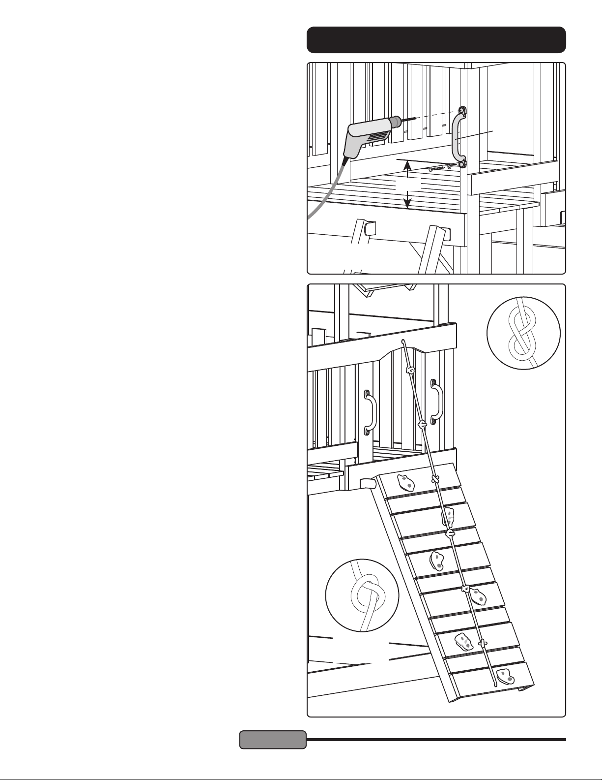
STEP 27 — Front Hand Grip:
Hold one Hand Grip (AQ) against the front face of the front
right post above the Access Ladder. The lower hole should
be 8" above the top of the platform.
Drill 3/16" diameter pilot holes 1" deep into the post through
the holes in the Hand Grip. Fasten using 1/4 x 1-1/2" Lag
Screws and Flat Washers.
STEP 28 — Climbing Rope:
Note the 5/8" diameter hole above the arch in the Right Wall
Support.
Push one end of the Climbing Rope (AR) through the hole in
the Right Wall Support. Tie a gure-eight knot at the end of
the rope, inside the gym. Leave at least 3" of rope extending
beyond the knot inside the gym.
From the outside of the gym, tie an overhand knot approximately every 9" along the length of the rope. Make sure each
knot is tight.
Push the loose end of the rope through the hole in the Bot-
tom Rope Support. Pull the rope taut and tie a gure-eight
knot to secure it.
Set the Climber Rails into the playground surface to ensure that the bottom rope connection is as close to the
ground as possible.
IMPORTANT: Check the rope often. At no time should
the bottom end of the rope be untied or the rope loose
enough to form a loop. This presents extreme danger to
your children.
ASSEMBLY INSTRUCTIONS
AW
8"
3/16" Pilot Drill & 1/4" x
1-1/2" Lag Screw
Figure Eight
Knot
If the rope is too
long you can tie
extra knots along
the length of the
rope. If too short,
remove knots.
© Copyright 2014, Creative Playthings
Page 19
Overhand
Knot
MODEL PS18EAS
19862-600 Rev E (01-19)
Page 20
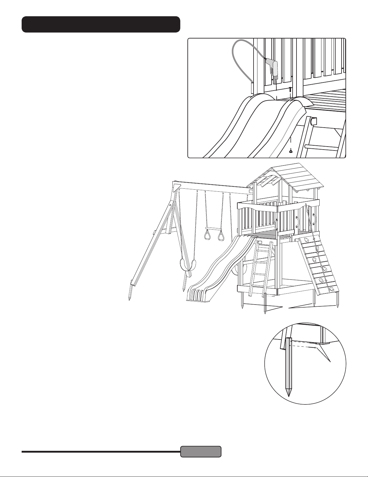
ASSEMBLY INSTRUCTIONS
STEP 29 — Slide:
Place your Slide in the opening in the tower front as shown.
Pull it tight to the platform until it stops against the Platform.
Check that the Slide extends out perpendicular from the play
set.
Using the holes in the slide for guides, drill two 5/16" diameter holes through the Platform Boards and secure the Slide
using two 1/4" x 1" Truss Head Bolts from the top and 1/4"
Weld Nuts from below.
Note: Depending on the Slide, you may nd that the holes
you drill encounter a framing member. If so, stop drilling after
piercing the Deck Board. Loosen the Deck Board and insert
the Weld Nuts from the underside. If desired, a 1" spade drill
bit can be used to clear a space for the base of the Weld Nut
in the Framing Member. Re-attach the Platform Board and
continue securing the Slide.
STEP 30 — Swing Beam & Swings:
Install the Swing Beam as instructed by the assembly
guide included with the Beam. The nameplate is included in box one of this tower.
Hang the Swings and Ring Trapeze in the positions shown below. U.S. safety standards require a
minimum clearance of 8" from the bottom of each
Swing Accessory to the ground. U.K. (& E.U.)
safety standards require a minimum clearance of
350mm (13-3/4") between the bottom of each
Swing Accessory and the ground.
The height of each Swing Accessory is adjusted by using a different link in the chain.
Be sure to hang the Swings Accessories
with ground clearance greater than or
equal to the safety standard for your
region.
STEP 31 — Ground Stakes:
U
Hammer two Ground Stakes next to the Front Left Post and Back Right Post as shown.
The top of the Ground Stake should be minimum of 1/8" below the top of the Sandbox Sides.
Secure each stake to the adjacent Sandbox Side using two #8 x 2" Screws through the predrilled holes.
Hammer Ground Stakes next to the Access Ladder and Cargo Upright as shown. Secure
each stake with two #8 x 2-1/2" Screws through the pre-drilled holes. Secure the Beam Legs
in the same manner.
Note: Do NOT use concrete to set Ground Stakes. Pound a metal spike or rod into the
ground to start a hole in hard or rocky ground.
Inspect your work; make sure all fasteners are secured properly and the area is clear
of hazards before allowing children on the Swing Set.
#8 x 2-1/2"
Screw
Save all instruction sheets and receipts in case it becomes necessary to contact
Creative Playthings for warranty service and/or part replacement. The warranty
can be found in your Owner’s Manual.
MODEL PS18EAS
19862-600 Rev E (01-19)
Page 20
© Copyright 2014, Creative Playthings
 Loading...