

Page 1
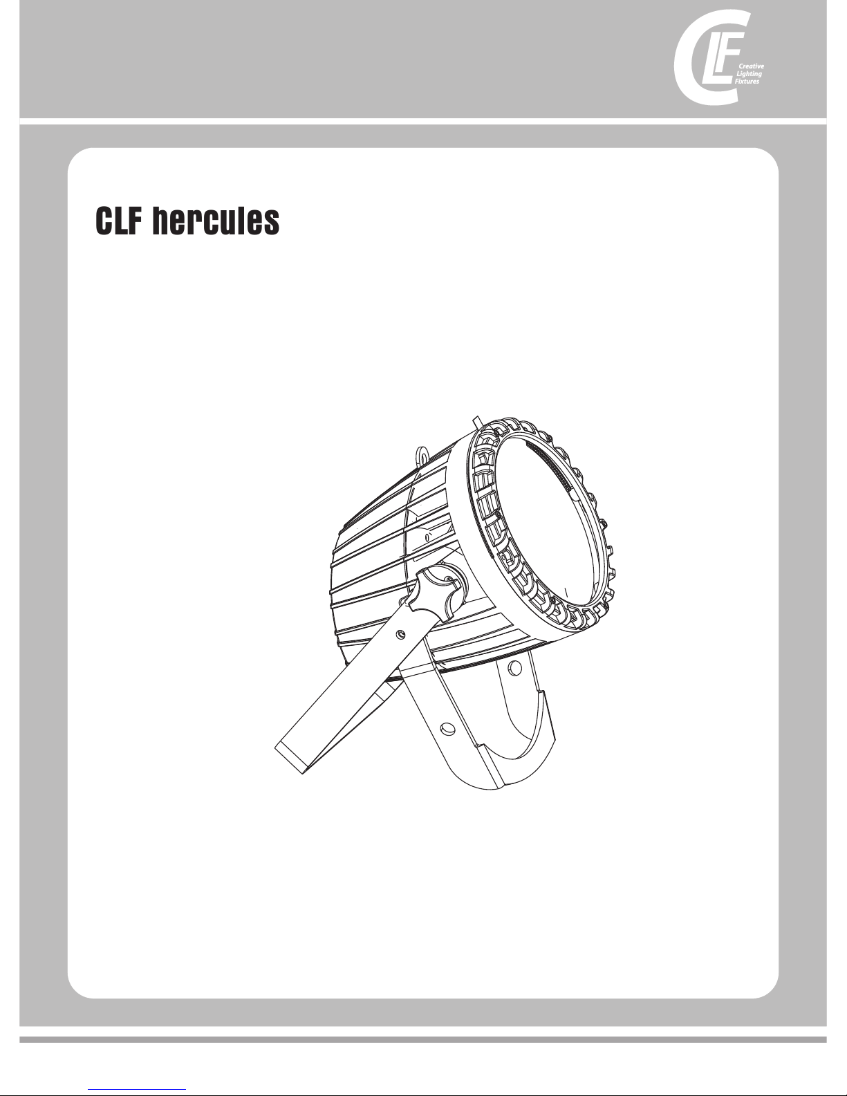
CLF hercules
V 1.0 JANUARY 2015
Page 2
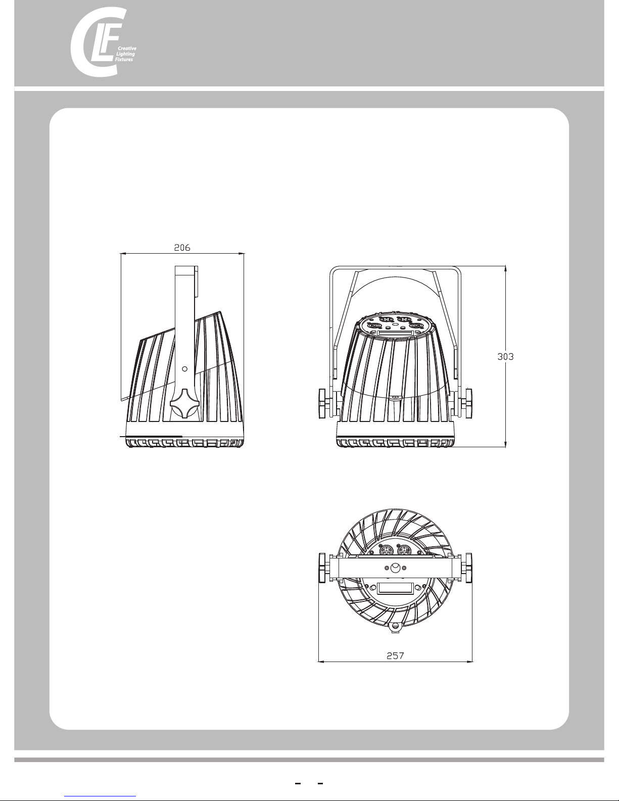
Dimensions
All dimensions are in millimeters
2
Page 3
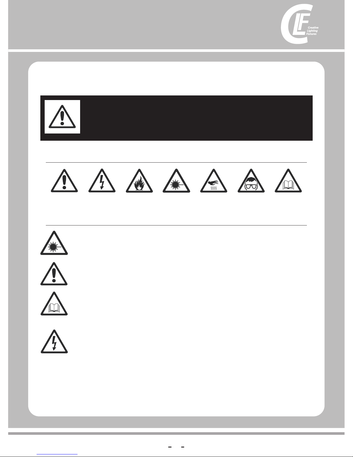
Safety Information
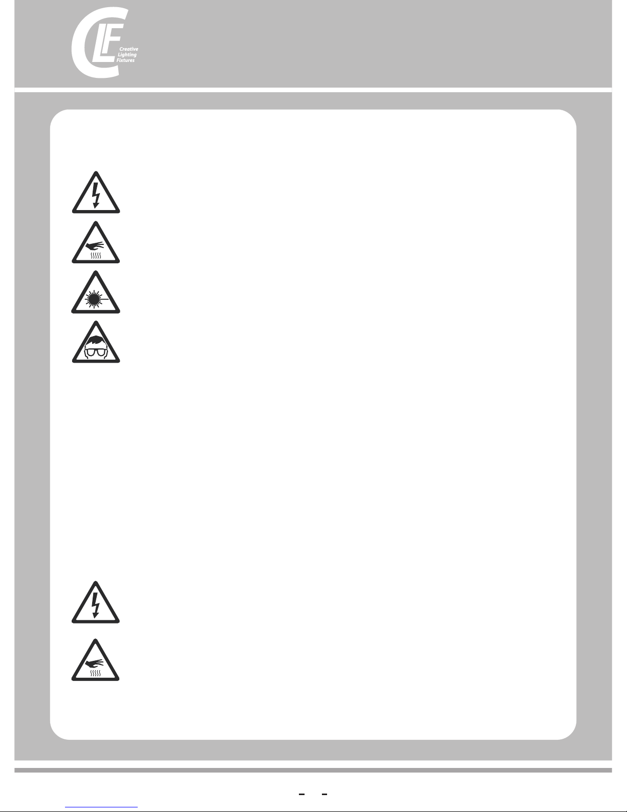
The fo llowing s ymbols ar e used to ide ntify imp ortan t safety in formati on on the pro duct and in t his manua l:
WARNING!
Read the safety precautions in this section before
installing, powering, operating or servicing this
product
DANGER!
Safety ha za rd.
Risk of sev er e
injury or d ea th.
DANGER!
Hazardo us
voltage . Ri sk of
lethal or s ev ere
electri c sh ock.
WAR NING!
Fire haza rd .
WAR NING!
LED light
emissio n. R isk of
eye injur y.
WAR NING!
Burn haza rd . Hot
surface . Do n ot
touch.
WAR NING!
Wea r pr ot ectiv e
eyewear .
WAR NING!
Refer to us er
manual.
Warning! Risk Group 3 (high risk) LED product according to EN 62471. Do not look into the beam at a distance
of less than 8.3 meters from the front surface of the product. Do not view the light output with optical
instruments or any device that may concentrate the beam.
l
lAlways ground (earth) the fixture electrically.
lUse only a source of AC power that complies with local building and electrical codes and has both overload and
ground-fault (earth-fault) protection.
lBefore using the fixture, check that all power distribution equipment and cables are in perfect condition and rated for
the current requirements of all connected devices.
lPower input and through put cables must be3-conductor, rated 20 A minimum, 1.5 mm² (16 AWG) minimum
conductor size,Power input and through put cables must be3-conductor, rated 20 A minimum, 1.5 mm² (16 AWG)
minimum conductor size ,exrta hard usage type(ST or equivalent). The cable must be heat-rewistant to 90° C (194° F)
minimum.
lUse only PowerCon cable connectors to connect to power input sockets. Use only PowerCon cable connectors to
connect to power throughput sockets.
lIsolate the fixture from power immediately if the power plug or any seal, cover, cable, or other component is
damaged, defective, deformed, wet or showing signs of overheating. Do not reapply power until repairs have been
completed.
This product is for professional use only. It is not for household use.
This product presents risks of severe injury or death due to fire and burn hazards, electric shock and falls.
Read this manual before installing, powering or servicing the fixture, follow the safety precautions listed below and
observe all warnings in this manual and printed on the fixture. If you have questions about how to operate the fixture
safely, please contact your supplier
PROTECTION FROM ELECTRIC SHOCK
Disconnect the fixture from AC power before removing or installing any cover or part and when not in use.
3
Page 4
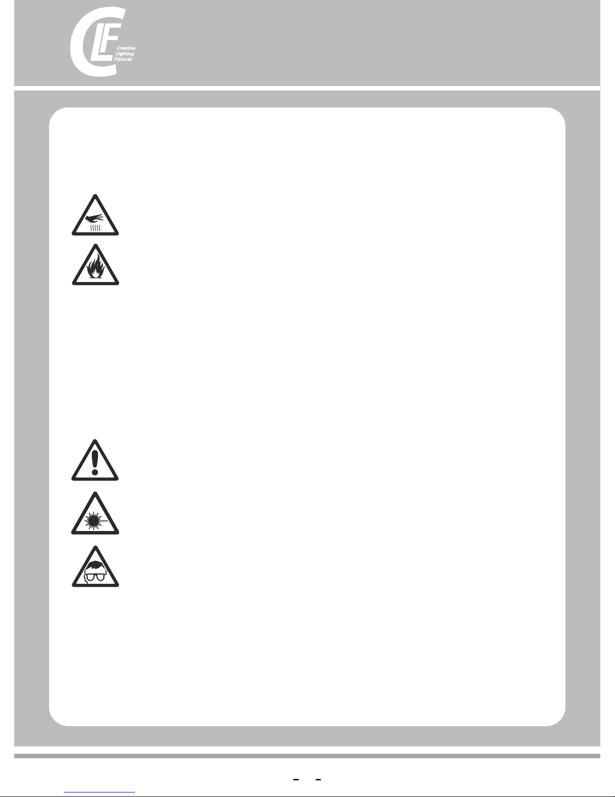
lDo not expose the fixture to rain or moisture.
lRefer any service operation not described in this manual to a qualified technician.
lSocket outlets used to supply fixture fixtures with power or external power switches must be located near the fixtures
and easily accessible so that the fixtures can easily be disconnected from power.
lDo not operate the fixture if the ambient temperature (Ta) exceeds 40° C (104° F).
lThe exterior of the fixture becomes hot during use. Avoid contact by persons and materials. Allow the fixture to
cool for at least 10 minutes before handling.
lKeep all combustible materials (e.g. fabric, wood, paper) at least 100 mm (3.9 in.) away from the head.
lKeep flammable materials well away from the fixture.
lEnsure that there is free and unobstructed airflow around the fixture.
lDo not illuminate surfaces within 200 mm (7.9 ins.) of the fixture.
lDo not attempt to bypass thermostatic switches or fuses.
lIf you relay power from one fixture to another using power throughput sockets, do not connect more than ten fixture
fixtures in total to each other in an interconnected chain.
lConnect only other fixture fixtures to fixture power throughput sockets. Do not connect any other type of device to these
sockets.
lDo not stick filters, masks or other materials onto any optical component.
lDo not modify the fixture in any way not described in this manual
lDo not look continuously at LEDs from a distance of less than 8.3 meters (27 ft. 3 inches) from the front surface of the
fixture without protective eyewear such as shade 4-5 welding goggles. At less than this distance, the LED emission can
cause eye injury or irritation. At distances of 8.3 meters (27 ft. 3 inches) and above, light output is harmless to the naked
eye provided that the eye’s natural aversion response is not overcome.
lDo not look at LEDs with magnifiers, telescopes, binoculars or similar optical instruments that may concentrate the light
output.
lEnsure that persons are not looking at the LEDs from within 8.3 meters (27 ft. 3 inches) when the product lights up
suddenly. This can happen when power is applied, when the product receives a DMX signal, or when SERVICE menu
items are selected.
lFasten the fixture securely to a fixed surface or structure when in use. The fixture is not portable when installed.
lEnsure that any supporting structure and/or hardware used can hold at least 10 times the weight of all the devices they
support.
lAllow enou gh c le ar an ce a ro un d th e he ad t o ensure that it cannot collide with an object or a no th er f ix tu re w he n
it moves.
lCheck that a ll e xt er na l co ve rs a nd r ig gi ng hardware are securely fastened.
lBlock acce ss b el ow t he w or k ar ea a nd w or k fr om a stable platform whenever installing, ser vi ci ng o r mo vi ng
the fixture.
lDo not opera te t he f ix tu re w it h mi ss in g or d amaged covers, shields or any optical compone nt .
PROTECTION FROM BURNS AND FIRE
PROTECTION FROM INJURY
4
Page 5

Contents
Dime nsions . . . . . . . . . . . . . . . . . . . . . . . . . . . . . . . . . . . . . . . . . . . . . . . . . . . . . . . . . . . . . . . . . . . . . . . . 2
Safe ty Inform ation. . . . . . . . . . . . . . . . . . . . . . . . . . . . . . . . . . . . . . . . . . . . . . . . . . . . . . . . . . . . . . . . . . 3
Fixt ure overv iew . . . . . . . . . . . . . . . . . . . . . . . . . . . . . . . . . . . . . . . . . . . . . . . . . . . . . . . . . . . . . . . . . . . 6
Intr oductio n . . . . . . . . . . . . . . . . . . . . . . . . . . . . . . . . . . . . . . . . . . . . . . . . . . . . . . . . . . . . . . . . . . . . . . . . 7
Usin g for the f irst t ime . . . . . . . . . . . . . . . . . . . . . . . . . . . . . . . . . . . . . . . . . . . . . . . . . . . . . . . . . . . . . . . 7
AC power . . . . . . . . . . . . . . . . . . . . . . . . . . . . . . . . . . . . . . . . . . . . . . . . . . . . . . . . . . . . . . . . . . . . . . . . . . 8
Powe r volt age . . . . . . . . . . . . . . . . . . . . . . . . . . . . . . . . . . . . . . . . . . . . . . . . . . . . . . . . . . . . . . . . . . . . . 8
Powe r cabl es and pow er plu g . . . . . . . . . . . . . . . . . . . . . . . . . . . . . . . . . . . . . . . . . . . . . . . . . . . . . . . . . 8
Rela ying p ower t o othe r devi ces . . . . . . . . . . . . . . . . . . . . . . . . . . . . . . . . . . . . . . . . . . . . . . . . . . . . . . . 9
Data link . . . . . . . . . . . . . . . . . . . . . . . . . . . . . . . . . . . . . . . . . . . . . . . . . . . . . . . . . . . . . . . . . . . . . . . . . . 9
Conn ecting t he data l ink . . . . . . . . . . . . . . . . . . . . . . . . . . . . . . . . . . . . . . . . . . . . . . . . . . . . . 9
Tip s for reliab le data transm ission . . . . . . . . . . . . . . . . . . . . . . . . . . . . . . . . . . . . . . . . . . . . . . . . . . . . . . . . . . . 9
Phys ical in stallat ion . . . . . . . . . . . . . . . . . . . . . . . . . . . . . . . . . . . . . . . . . . . . . . . . . . . . . . . . . . . . . . . 10
Fast ening the fi xture to a fl at sur face. . . . . . . . . . . . . . . . . . . . . . . . . . . . . . . . . . . . . . . . . . . . . . . . . . . 10
Setup. . . . . . . . . . . . . . . . . . . . . . . . . . . . . . . . . . . . . . . . . . . . . . . . . . . . . . . . . . . . . . . . . . . . . . . . . . . . . 11
Control panel and menu navigation . . . . . . . . . . . . . . . . . . . . . . . . . . . . . . . . . . . . . . . . . . . . . . . . . . . . 11
DMX address setting . . . . . . . . . . . . . . . . . . . . . . . . . . . . . . . . . . . . . . . . . . . . . . . . . . . . . . . . . . . . . . . 11
WDMX control . . . . . . . . . . . . . . . . . . . . . . . . . . . . . . . . . . . . . . . . . . . . . . . . . . . . . . . . . . . . . . . 11
Control mode . . . . . . . . . . . . . . . . . . . . . . . . . . . . . . . . . . . . . . . . . . . . . . . . . . . . . . . . . . 12
Dimming . . . . . . . . . . . . . . . . . . . . . . . . . . . . . . . . . . . . . . . . . . . . . . . . . . . . . . . . . . 12
Restoring factory default settings . . . . . . . . . . . . . . . . . . . . . . . . . . . . . . . . . . . . . . . . . . . . . . . . . . . . . 12
Operation and effects . . . . . . . . . . . . . . . . . . . . . . . . . . . . . . . . . . . . . . . . . . . . . . . . . . . . . . . . . . . . . 12
Effects . . . . . . . . . . . . . . . . . . . . . . . . . . . . . . . . . . . . . . . . . . . . . . . . . . . . . . . . . . . . . . . . . . . . . . . . . . 12
Filter sheet . . . . . . . . . . . . . . . . . . . . . . . . . . . . . . . . . . . . . . . . . . . . . . . . . . . . . . . . . . . . . 13
Service and maintenance. . . . . . . . . . . . . . . . . . . . . . . . . . . . . . . . . . . . . . . . . . . . . . . . . . . . . . . . . . 14
Cleaning. . . . . . . . . . . . . . . . . . . . . . . . . . . . . . . . . . . . . . . . . . . . . . . . . . . . . . . . . . . . . . . . . . . . . . . . . 14
DMX protocol . . . . . . . . . . . . . . . . . . . . . . . . . . . . . . . . . . . . . . . . . . . . . . . . . . . . . . . . . . . . . . . . . . . . . 15
Onboard control menus. . . . . . . . . . . . . . . . . . . . . . . . . . . . . . . . . . . . . . . . . . . . . . . . . . . . . . . . . . . . 17
Specifications . . . . . . . . . . . . . . . . . . . . . . . . . . . . . . . . . . . . . . . . . . . . . . . . . . . . . . . . . . . . . . . . . . . . . 18
5
5
Page 6
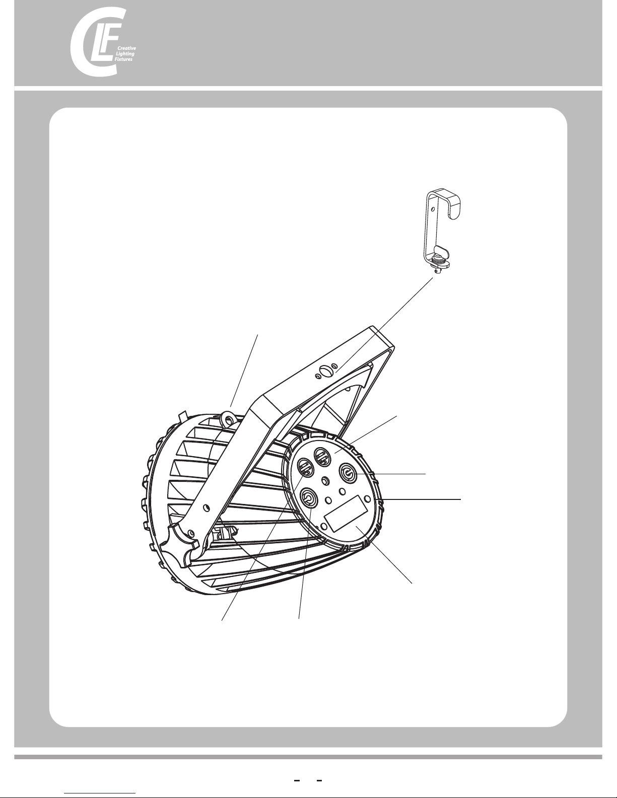
Fixture overview
Control buttons
Safety cable attachment point
Display
DMX input
DMX output
AC mains power
throughput
AC mains power
input
No te: h ead f an g ril l in pr odu cti on mode ls is r ota ted 9 0° c omp are d to th is il lu str ati on.
G Clam p with
Quic klock # 875 760
(Opt ional)
6
Page 7
Introduction
lThis compact LED-based Parcan features:
lRGBW color control with color temperature control
l6 in 1 LED (Red,Green,Blue,White,Amber,Purple)
lOnboard control panel and backlit LCD graphic display
lSmooth electronic dimming
lElectronic shutter with strobe and pulse effects
lDMX control
lchoose different degrees of filter sheet to change the shape of the light
Warning! Read “Safety Information” o n pa ge 3 b ef or e in st al li ng , po we ri ng, operating or servicing the
fixture. Bef or e ap pl yi ng p ow er t o th e fi xt ur e:.
lCarefull y re vi ew “ Sa fe ty I nf or ma ti on ” starting on page 3.
lCheck that the l oc al AC m ai ns p ow er s ou rc e is w ithin the fixture’s po we r voltage and frequency ranges.
lSee “Power c ab le s an d po we r pl ug ” on p ag e 8. I nstall a PowerCon power input connector on a su it ab le
power cabl e. I f dr aw in g po we r fr om a m ai ns p ower outlet, install a suitable power plug on t he p ow er c ab le .
Using for the first time
7
Page 8
AC power
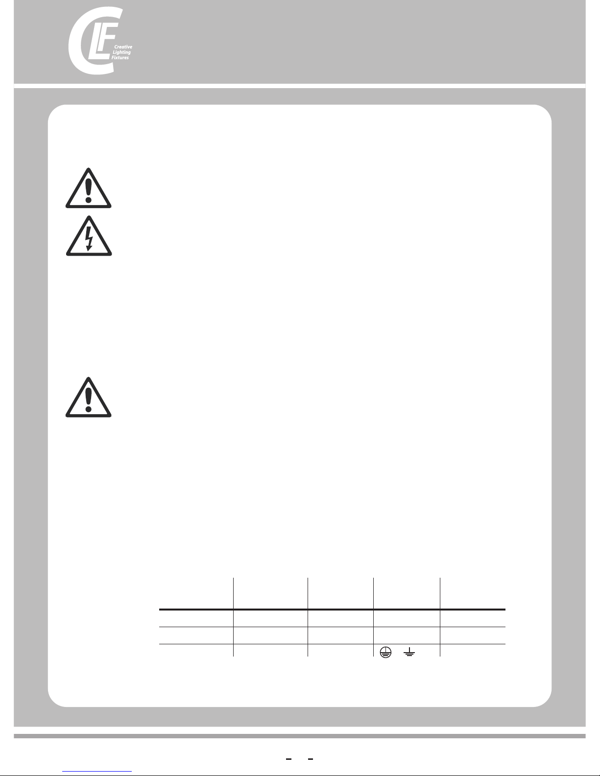
Wire Color
(EU models)
Wire Color
(US models) Conductor Symbol Screw (US)
brown black live L yellow or brass
blue white neutral N silver
yellow/green green ground (earth) or green
Warning Read “Safety Information” starting on page 3 before connecting the fixrures to AC mains power.
Warning! For protection from electric shock, the fixture must be grounded (earthed). The powerdistribution
circuit must be equipped with a fuse or circuit breaker and ground-fault (earth-fault)protection.
Warning! Socket outlets or external power switches used to supply the fixture with power must be located
near the fixture and easily accessible so that the fixtures can easily be disconnected from power.
Important! Do not insert or remove live PowerCon connectors to apply or cut power, as this may cause arcing at
the terminals that will damage the connectors.
Important! Do not use an external dimming system to supply power to the fixture, as this may cause damage to
the fixture that is not covered by the product warranty.
The can be hard-wired to a building electrical installation if you want to install it permanently, or a power plug that is
suitable for the local power outlets can be installed on the power cable.
,
Warning! Check that the voltage range specified on the fixtures serial number label matches the local AC mains
power voltage before applying power to the fixture.
The fixtures accept AC mains power at 100-240 V nominal, 50/60 Hz. Do not apply AC mains power to the fixture at any
other voltage than that specified on the fixture’s serial number label.
Power input and throughput cables must be rated 20 A minimum, have three conductors 1.5 mm² (16 AWG) minimum
conductor size and an outer cable diameter of 5 - 15 mm (0.2 - 0.6 in.). Cables must be hard usage type (SJT or
equivalent) and heat-resistant to 90° C (194° F) minimum. In the EU the cable must be HAR approved or equivalent.
If you install a power plug on the power cable, install a grounding-type (earthed) plug that is rated 20 A minimum. Follow
the plug manufacturer’s instructions. Table 1 shows standard wire color-coding schemes and some possible pin
identification schemes; if pins are not clearly identified, or if you have any doubts
!
fixture
Table 1: Wire color-codig and power connections
Power voltage
Power cables and power plug
8
Page 9
Warning!
Power can be relayed to another device via the light-grey PowerCon throughput socket that accepts a light-grey
PowerCon cable connector. Note that blue input and light-grey throughput connectors have different designs: one type
cannot be connected to the other.
If you link fixtures in a chain so that they all draw AC mains power via the first fixture, certain points must be respected:
2
lA hard usage, three-conductor, 16 AWG or 1.5 mm cable with SJT or equivalent cable jacket must be used to connect
the first fixture to AC mains power and to interconnect all the fixtures in the chain up to a maximum of seven fixtures in
total.
lLight-grey PowerCon connectors must be used to draw AC mains power from the fixtures' power throughput sockets
and blue PowerCon connectors must be used to supply power at the fixture's power input sockets.
lNo matter what the AC mains power voltage is, do not connect more than ten fixture fixtures in total(i.e. including the
first fixture) to AC mains power in one interconnected daisy chain using power input and throughput connectors.
Do not connect more than ten fixture fixtures in total to AC mains power in one interconnected chain
Relaying power to other devices
Data link
A DMX 512 data link is required in order to control a fixture via DMX.
The fixture has 3-pin XLR connectors for DMX data input and output. The pin-out on all connectors is pin 1 = shield,
pin 2 = cold (-), and pin 3 = hot (+).
Or the fixture has 5-pin XLR connectors for DMX data input and output. The pin-out on all connectors is
pin 1 = shield , pi n 2 = co ld ( -) , an d pi n 3 = ho t (+ ). P in s 4 an d 5 in the 5-pin XLR connectors are not used
To add more fixtures or groups of fixtures when the above limit is reached, add a DMX universe and another daisychained link.
Use shielded twisted-pair cable designed for RS-485 devices: standard microphone cable cannot transmit control data
reliably over long runs. 24 AWG cable is suitable for runs up to 300 meters. Heavier gauge cable and/or an amplifier is
recommended for longer runs.
To connect the fixture to data:
1. Connect the DMX data output from the controller to the closest fixture’s male 3-pin XLR DMX input connector.
2. Connect the DMX output of the fixture closest to the controller to the DMX input of the next fixture and continue
connecting fixtures output to input.
Tips for reliable data transmission
Connecting the data link
9
Page 10
Physical installation
Warning! The fixture must be either fastened to a flat surface such as a stage or wall, or clamped to a truss or
similar structure in any orientation using a rigging clamp. Do not apply power to the fixture if it is standing freely
or the fixture can be moved.
Warning! If the fixture can cause injury or damage it if falls, attach an approved safety cable to one of the safety
cable attachment points on the base (see “Fixture overview” on page 6).
Check that all surfaces to be illuminated are minimum 200 mm. from the fixture, that combustible materials
(wood, fabric, paper, etc.) are minimum 100 mm. from the head, that there is free airflow around the fixture and
that there are no flammable materials nearby.
Make sure that it is impossible for the moving head to collide with another fixture or other object...
The can be fastened to a fixed flat surface that is oriented at any angle. Check that the surface can support at least
10 times the weight of all fixtures and equipment to be installed on it.
Warning! The supporting surface must be hard and flat or air vents in the base may be blocked, which will cause
overheating. Fasten the fixture securely. Do not stand it on a surface or leave it where it can be moved or can fall
over. Attach a securely anchored safety cable to the safety cable attachment point (see “Fixture overview” on
page 6) if the fixture is to be installed in any location where it may fall and cause injury or damage if the primary
attachment fails.
fixture
Fastening the fixture to a flat surface
3. Block access under the work area. Working from a stable platform, hang the fixture on the truss with the
arrow on the base towards the area to be illuminated. Tighten the rigging clamp.
4. Secure the fixture against clamp failure with a secondary attachment such as an approved safety cable
that is rated for the weight of the fixture using one of the attachment points at the edges of the base (see
“Fixture overview” on page 6). Do not use any other part of the fixture as a safety cable attachment
point.
5. Check that the head will not collide with other fixtures or objects.
10
Page 11
Setup
Warning! Read “Safety Information” on page 3 before installing, powering, operating or servicing
the fixture.
The onboard control panel and backlit graphic display are used to set the 's DMX address,
configure individual fixture settings (personality), read out data and execute service utilities. See “Onboard
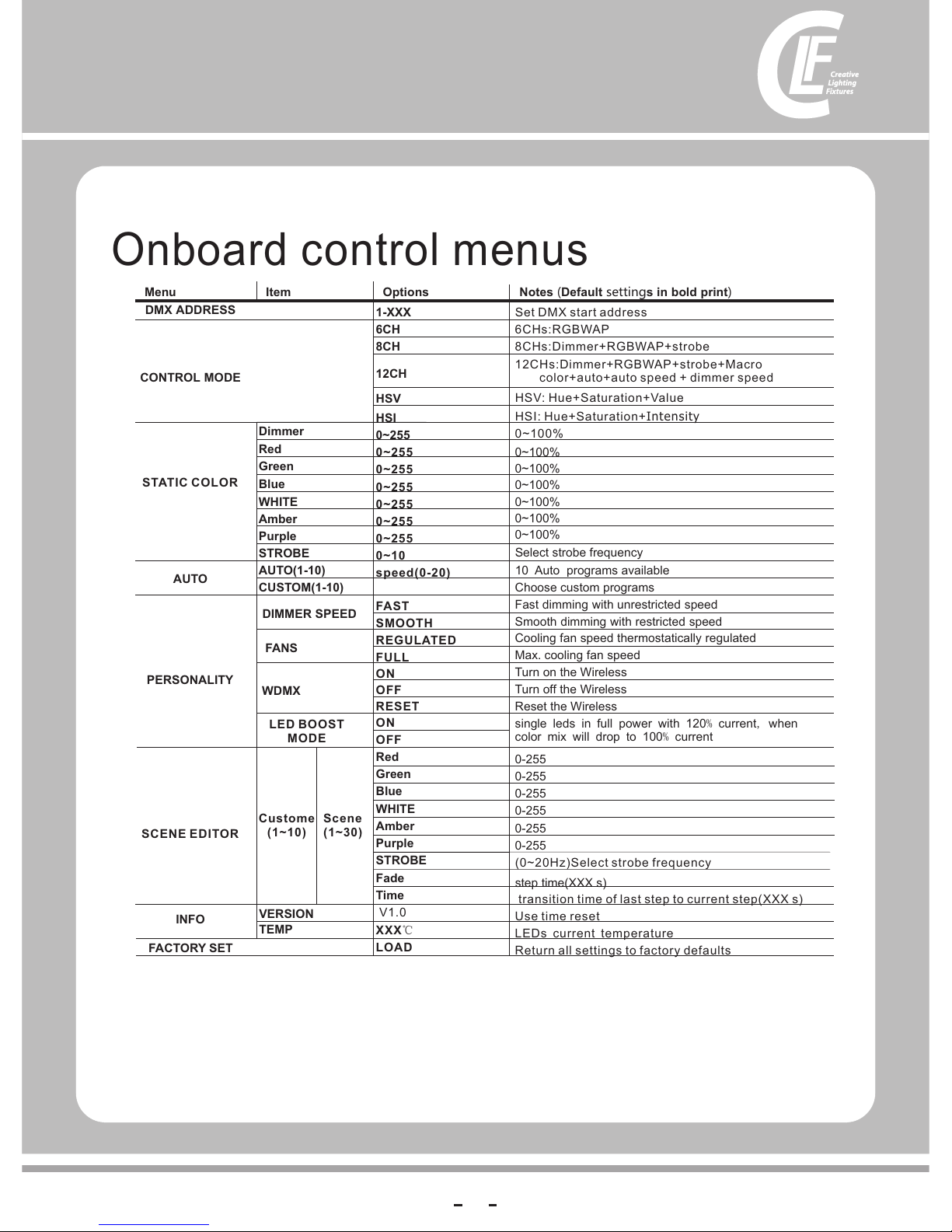
control menus” on page 22 for a complete list of menus and commands.
Using the control buttons
lTo enter a menu, select a function or apply a selection, press (Enter).
lPress (Up) and (Down) to scroll within a menu or adjust values.
lTo escape a function or move back one level in the menu structure, press (MODE).
l
The DMX address, also known as the start channel, is the first channel used to receive instructions from the controller.
For independent control, each fixture must be assigned its own control channels.
The DMX address is configured using the DMX ADDRESS menu in the control panel.
Press the button “UP” to switch off Wireless DMX or disconnect with all connected Transmitters.
Press the bu tt on “D OW N' t o se t th e un it i n th e ”r ea dy to connect with all not connected transm it te rs '
mode. If you p re ss t he m od e bu tt on o n th e Wi re less solution transmitter all the ready to co nn ec t un it s
will be conn ec te d.
If the unit is suc ce ss fu ll y co nn ec te d in t he home display the sign“ ”. Appears. If the unit is n ot
connecte d to a t ra ns mi tt er o r sw it ch ed o ff n o“ ”. s ig n is v is ib le
fixture
►
▲ ▼
◄
Holding down the "UP" or "DOWN" button for more than 3 seconds, the MENU display rotated 180°
lIn order to facilitate for inspection the signal, If the display to flicker when it's not receiving any signalNotes
Control panel and menu navigation
DMX address setting
WDMX control
11
Page 12
lFAST is the default setting. It gives a virtually instantaneous reaction when you dim from one intensity to another, but
dimming slowly from one intensity to another may appear slightly uneven.
lThe SMOOTH setting gives smoother dimming during slow changes in intensity, but it limits the speed of dimming
changes slightly. This makes it ideal for slow, smooth dimming, but a short time-lag may be noticeable if you try to dim
quickly from one intensity to another.
The fixture factory default settings can be restored by applying a FACTORY SETTING → LOAD command.
Restoring factory default settings
Standard Manual
DMX control mode is selected in the CONTROL MODE menu. The fixture has five DMX control
modes:
l
l Red+Green+Blue+White+Amber+Purple
l Red+Green+Blue+White+Amber+Purple
l
Intensity
and modes
Red+Green+Blue+White+Amber+Purple6 channels :
8 channels :Dimmer+ + strobe
12 channels :Dimmer++ + strobe+Macro + strobe + AUTO + AUTO
speed+ dimming speed
HSV: Hue+Saturation+Value
lHSI: Hue+Saturation+
CONTROL MODE
12
Dimming
Operation and effects
Warning! Read “Safety Information” starting on page 3 before installing, powering, operating or servicing the
fixture.
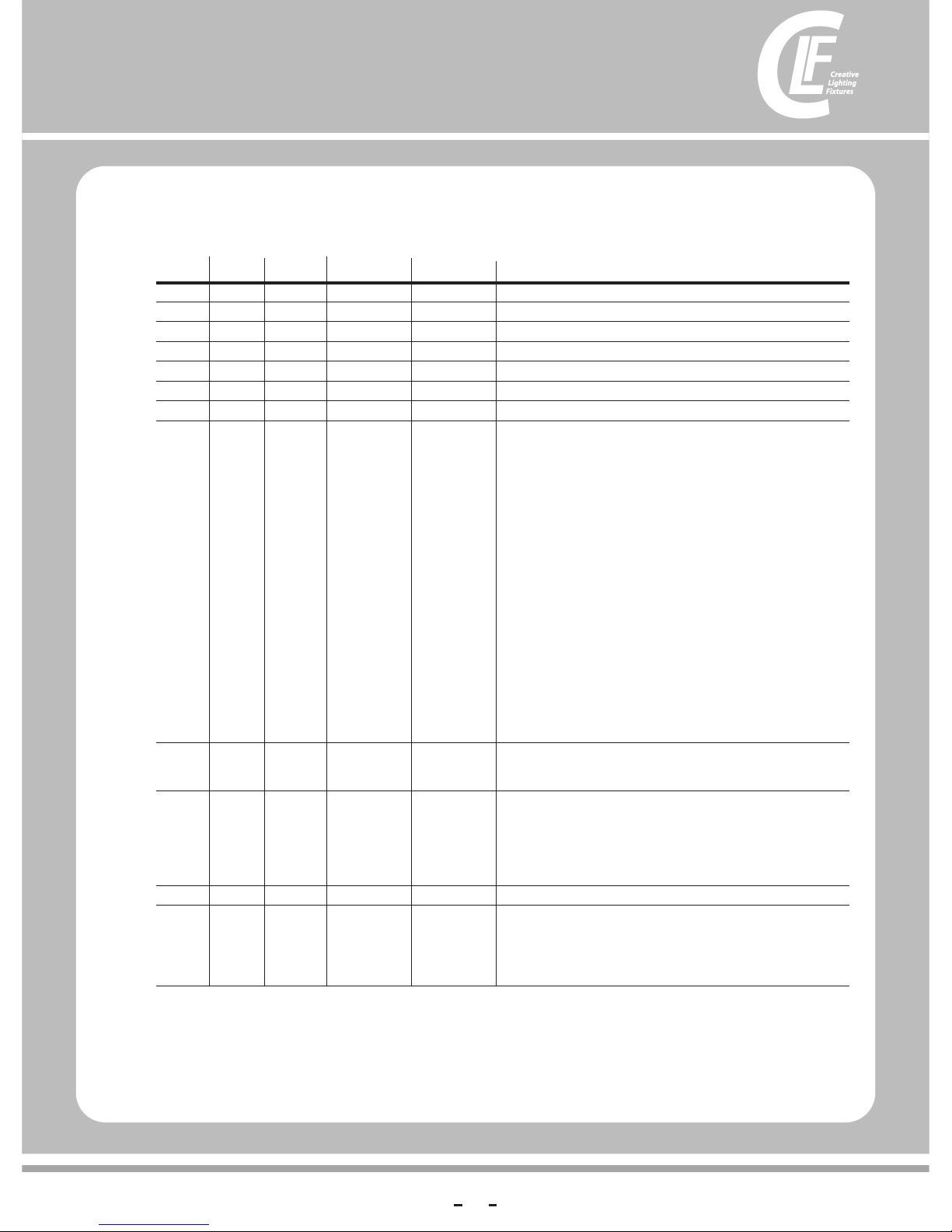
This section describes only DMX control features that require particular explanation. See “DMX protocols”on page 16
for a full list of the DMX channels and values required to control the different effects.
Shutter effect
The electronic ‘shutter’ effect available for the fixture provides instant open and blackout,
variable speed regular and random strobe and opening/closing pulse effects as well as burst and sine wave effects.
Controlling color
Effects
Page 13
13
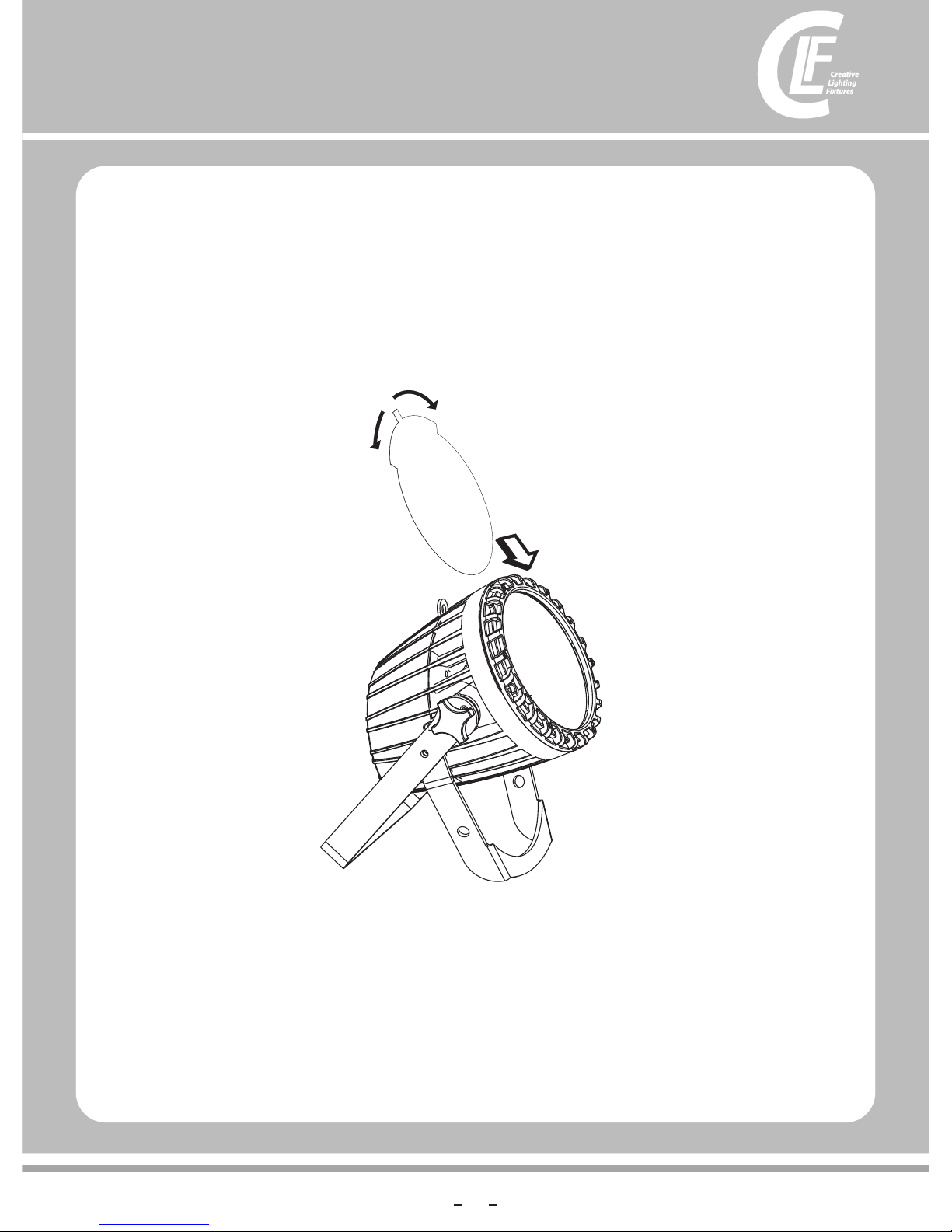
Filter sheet
90°
You ca n choose differen t de gr ees of filter to cha ng e the shape of the li gh t, and can
chan ge t he Angle of the lig ht r otating fil te r sheet
shee t
Page 14
16
Service and maintenance
Warning Read “Safety Information” on page 3 before servicing the fixture.
Warning! Disconnect the fixture from AC mains power and allow to cool for at least 10 minutes before handling.
Do not view the light output from less than 8.3 meters (27 ft. 3 inches) without shade 4-5 welding goggles. Be
prepared for the fixture to light suddenly if connected to power.
Warning! Refer any service operation not described in this user manual to a qualified service technician.
Important! Excessive dust, smoke fluid, and particle buildup degrades performance, causes overheating and will
damage the fixture. Damage caused by inadequate cleaning or maintenance is not covered by the product
warranty.
It is policy to apply the strictest possible calibration procedures and use the best quality materials available to ensure
optimum performance and the longest possible component lifetimes. However, LEDs are subject to wear and tear over the
life of the product, resulting in gradual changes in color and overall brightness over many thousands of hours of use. The
extent of wear and tear depends heavily on operating conditions and environment, so it is impossible to specify precisely
whether and to what extent LED performance will be affected. However, you may eventually need to ask Professional to
replace LEDs if their characteristics are affected by wear and tear after an extended period of use and if you require
fixtures to perform within very precise optical and color parameters.
The manufacturer’s LED lifetime data is based on performance under the manufacturer’s test conditions. As with all LEDs,
the gradual reduction in luminous output will be accelerated when LEDs are used in a fixture, where conditions are much
tougher than in manufacturer’s testing. To maximize LED lifetimes, keep the ambient temperature as low as possible and
drive the LEDs no harder and for no longer than necessary
Cleaning schedules for lighting fixtures vary greatly depending on the operating environment. It is therefore impossible to
specify precise cleaning intervals for the fixture. Environmental factors that may result in a need for frequent cleaning
include:
lUse of smoke or fog machines.
lHigh airflow rates (near air conditioning vents, for example).
lPresence of cigarette smoke.
lAirborne dust (from stage effects, building structures and fittings or the natural environment at outdoor events, for
example).
If one or more of these factors is present, inspect fixtures within their first 100 hours of operation to see whether cleaning
is necessary. Check again at frequent intervals. This procedure will allow you to assess cleaning requirements in your
particular situation.
Use gentle pressure only when cleaning, and work in a clean, well-lit area. Do not use any product that contains solvents
or abrasives, as these can cause surface damage.
!
Cleaning
Warning Disconnect from power and allow to cool before cleaning.
To clean the fixture:
1. Disconnect the fixture from power and allow it to cool for at least 10 minutes.
2. Vacuum or gently blow away dust and loose particles from the outside of the fixture and the air vents at the back and
sides of the head and in the base with low-pressure compressed air.
3. Remove the central screw from the grill on the front of the head, remove the grill and clean the LED lenses by wiping
gently with a soft, clean lint-free cloth moistened with a weak detergent solution. Do not rub the surface hard: lift
particles off with a soft repeated press. Dry with a soft, clean, lint-free cloth or low-pressure compressed air. Remove
stuck particles with an unscented tissue or cotton swab moistened with glass cleaner or distilled water.
!
14
Page 15
DMX protocols
Percent
0 - 100
0 - 100
0 - 100
0 - 100
0 - 100
0 - 100
0 - 100
0 - 7
8 -9
10 - 25
26 - 27
28 - 33
34 - 35
36 - 41
42 - 43
44 - 49
50 - 51
52 - 57
58 - 59
60 - 65
66 - 67
68 - 73
74 - 75
76 - 81
82 - 83
84 - 89
90 - 91
92 - 97
98 - 100
0 - 4
5 - 80
81-100
0 - 4
5-23
24-47
48-70
71-94
95-100
0-100
0-20
21-40
41-60
61-80
81-100
DMX Value
0 - 255
0 - 255
0 - 255
0 - 255
0 - 255
0 - 255
0 - 255
0 - 19
20 - 24
25 - 64
65 - 69
70 - 84
85 - 89
90 - 104
105 - 109
110 - 124
125 - 129
130 - 144
145 - 149
150 - 164
165 - 169
170 - 184
185 - 189
190 - 204
205 - 209
210 - 224
225 - 229
230 - 244
245 - 255
0 - 10
11 - 205
206 - 255
000-010
011-060
061-120
121-180
181-240
241-255
0-255
0-051
52-101
102-152
153-203
204-255
6-CH
1
2
3
4
5
6
8-CH
1
2
3
4
5
6
7
8
12-CH
1
2
3
4
5
6
7
8
9
10
11
12
15
Functi on
Dimmer (0- 10 0% )
Red(0-10 0% )
Green(0- 10 0% )
Blue(0-1 00 %)
White(0- 10 0% )
Amber(0- 10 0% )
Purple(0 -1 00 %)
Electronic s hu tt er e ff ec t
Shutter clos ed
Shutter op en
Strobe 1 (fast → slow)
Shutter op en
Strobe 2: op en in g pu ls e fast → sl ow
Shutter op en
Strobe 3: clos in g pu ls e ( fast → slow)
Shutter op en
Strobe 4: ra nd om s tr ob e ( fast → slow)
Shutter op en
Strobe 5: ra nd om o pe ni ng p ul se ( fast → slow)
Shutter op en
Strobe 6:random closing pulse ( fast → slow)
Shutter op en
Strobe 7: bu rs t pu ls e ( fast → slow)
Shutter op en
Strobe 8: rand om b ur st p ul se ( fast → slow)
Shutter op en
Strobe 9:sine wave (f as t → sl ow )
Shutter op en
Strobe 10: b ur st ( fast → slow)
Shutter op en
No Functio n
Macro colo r co nt ro l
Macro CCT control
No Functio n
Auto 01
Auto 02
Auto 03
Auto 04
Auto (01-0 4) c ir cu la ti on
Auto speed ( sl ow→a st )
( )
Preset dim me r sp ee d fr om d is pl ay m en u
Dimmer spe ed m od e off
Dimmer spe ed m od e1 ( fa st s pe ed )
Dimmer spe ed m od e2 ( mi dd le s pe ed )
Dimmer spe ed m od e3 ( sl ow s pe ed )
Page 16
16
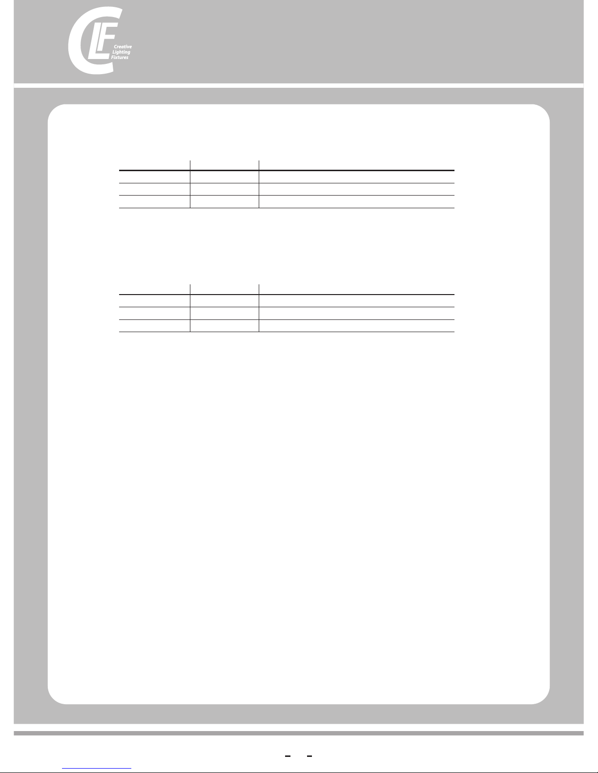
Note : In H SV mode, Hue stan ds f or the visibl e li ght, such as red, y el low, and
cyan , et c. Saturation r ef ers to the domi na nc e of hue in the col or ; when satura ti on
is at 10 0% , then the color is a t it s purest. Value is the col or 's brightne ss ; when
valu e is a t 100%, then the co lo r is at its brigh te st.
Channel
1
2
3
Value
000~255
000~255
000~255
Descript io n
Hue
Saturati on
Value (Intensity)
3 channels:HSV
Channel
1
2
3
Value
000~255
000~255
000~255
Descript io n
Hue
Saturati on
Intensity
3 channels:HSI
Page 17
17
Onboard control menus
Menu Item Options Notes (Default settings in bold print)
DMX ADDRESS
CONTROL MODE
1-XXX
6CH
8CH
12CH
HSV
HSI
0~255
0~255
0~255
0~255
0~255
0~255
0~255
0~10
speed(0- 20 )
FAST
SMOOTH
REGULATED
FULL
ON
OFF
RESET
ON
OFF
Red
Green
Blue
WHITE
Amber
Purple
STROBE
Fade
Time
V1.0
XXX℃
LOAD
Set DMX start ad dr es s
Macro
color+au to +a ut o sp ee d + di mm er s pe ed
HSV: Hu e+ Sa tu ra tion+Valu e
HSI: Hue+S at ur at io n+
Select strobe frequency
10 Auto programs available
(0~20Hz) Se le ct s tr ob e fr eq ue nc y
step time(
transition t im e of l as t st ep t o cu rr en t st ep (
6CHs:RGB WAP
8CHs:Dim me r+ RG BWAP+strobe
12CHs:Di mm er +R GB WAP+strobe+
In te nsity
0~100%
0~100%
0~100%
0~100%
0~100%
0~100%
0~100%
Choose custom programs
Turn on the Wireless
Turn off the Wireless
Reset the Wireless
single leds in full power with 120% current, when
color mix will drop to 100% current
0-255
0-255
0-255
0-255
0-255
0-255
XXX s)
XXX s)
Use time res et
LEDs curre nt t em pe ra tu re
Return all s et ti ng s to f ac to ry d ef au lt s
Fast dimming with unrestricted speed
Smooth dimming with restricted speed
Cooling fan speed thermostatically regulated
Max. cooling fan speed
STATI C CO LO R
Dimmer
AUTO(1-10)
CUSTOM(1-10)
Red
Green
Blue
WHITE
Amber
Purple
STROBE
AUTO
FANS
DIMMER SPEED
PERSONALITY
LED BOOST
MODE
WDMX
SCENE EDITOR
FACTORY SET
INFO
Custome
(1~10)
Scene
(1~30)
VERSION
TEMP
Page 18

Specifications
Physical
Length . . . . . . . . . . . . . . . . . . . . . . . . . . . . . . . . . . . . . . . . . . . . . . . . . . . . . .257 mm
Width . . . . . . . . . . . . . . . . . . . . . . . . . . . . . . . . . . . . . . . . . . . . . . . . . . . . . . .206 mm
Height . . . . . . . . . . . . . . . . . . . . . . . . . . . . . . . . . . . . . . . . . . . . . . . . . .303 mm
Weight . . . . . . . . . . . . . . . . . . . . . . . . . . . . . . . . . . . . . . . . . . . . . . . . 5.5 kg without accessories
Dynamic Effects
color mixing . . . . . . . . . . . . . . . . . . . . . . . . . . . . . . . . . . . . . . . . . . . . . . . . . . . . . . . . . . . . . . . RGBWAP
color temperature control . . . . . . . . . . . . . . . . . . . . . . . . . . . . . . . . . . . . . . CTO, variable 10 000 - 2500 K
. . . . . . . . . . . . . . . . . . . . . . . . . . . . . . . . . . . . . . . . . . . . . . . . . . . . . . . . . . . . . . . 12 PCS 6 in 1 LED
s h u t t e r e f f e c t s . . . . . . . . . . . . . . . . . . . El e ct r o n i c , w i t h r e g u l a r a n d r a n d o m
pulse, burst and strobe effects
. . . . . . . . . . . . . . . . . . . . . . . . . . . . . . . . . . . . . . . . . . . . . . . . . . . . . . . . . . . . 25°
Control and Programming
Control . . . . . . . . . . . . . . . . . . . . . . . . . . . . . . . . . . . . . . . . . . . . . . . . . . . . . . . . . . . . . . . . . . . . . . . . . .DMX
DMX channels . . . . . . . . . . . . . . . . . . . . . . . . . . . . . . . . . . . . . . . . . . . . . . . . . . . . . . . . . . . . . . . . 6/8/12/3/3
Setting and addressing . . . . . . . . . . . . . . . . . . . . . . . . . . . . . . . . Control panel with backlit graphic display
Protocol . . . . . . . . . . . . . . . . . . . . . . . . . . . . . . . .. . . . . . .. . . . . . .. . . . . . . . . . . . . . . . . . . . USITT DMX512-A
Construction
Color . . . . . . . . . . . . . . . . . . . . . . . . . . . . . . . . . . . . . . . . . . . . . . . . . . . . . . . . . . . . . . . . . . . . . . . . . . Black
Housing . . . . . . . . . . . . . . . . . . . . . . . . . . . . . . . . . . . . . . . . . . . High strength die-casting aluminum
Protection rating. . . . . . . . . . . . . . . . . . . . . . . . . . . . . . . . . . . . . . . . . . . . . . . . . . . . . . . . . . . . . . . . . . .IP 20
Installation
Orientation . . . . . . . . . . . . . . . . . . . . . . . . . . . . . . . . . . . . . . . . . . . . . . . . . . . . . . . . . . . . . . . . . . . . . . . .Any
Minimum distance to combustible materials . . . . . . . . . . . . . . . . . . . . . . . . . . 100 mm. from fixture
Minimum distance to illuminated surfaces . . . . . . . . . . . . . . . . . . . . . . . . . . . 200 mm. from fixture
Location . . . . . . . . . . . . . . . . . . . . . . . . . . . . . . . .Indoor use only, must be fastened to structure or surface
Connections
AC power input . . . . . . . . . . . . . . . . . . . . . . . . . . . . . . . . PowerCon input socket (blue)
AC power throughput. . . . . . . . . . . . . . . . . . . . . . . . . . .PowerCon output socket (grey)
DMX data in/out . . . . . . . . . . . . . . . . . . . . . . . . . . . . . . . . . . . . . . . . . . . . . . . . . . . . . . . . .3/5-pin locking XLR
Electrical
AC power . . . . . . . . . . . . . . . . . . . .. . . . . . . . . . . . . . .100-240 V nominal, 50/60 Hz
Maximum total power consumption . . . . . . . . . . . . . . . . . . . . . . . . . . . . . . . . . .105 W
Power supply unit . . . . . . . . . . . . . . . . . . . . . . . . . . . .Auto-ranging electronic switch mode
Power consumption, all effects static, zero light output . . . . . . . . . . . . . . . . . . . . . . . . <10 W
Thermal
Cooling . . . . . . . . . . . . . . . . . Forced air (temperature-regulated, low noise, user-definable levels)
Maximum ambient temperature (Ta max.). . . . . . . . . . . . . . . . . . . . . . . . . . . . . . 40° C
Minimum ambient temperature (Ta min.). . . . . . . . . . . . . . . . . . . . . . . . . . . . . . . 5° C
LED Quantity:
Beam Angle:
18
 Loading...