

Creative controls LogiTouch Installation Manual
3500
is approximately 20 yards. each one has its
own unique ID code so there is no danger of
operating another vehicle accidentally.
The cars existing controls are unaffected by
the transmitter signal and will operate as
normal. For the control to work correctly, the
car's controls should be set to turn indicators
off and lights on low beam.
INSTALLATION GUIDE
Up to 18 Functions
Wireless Handset Controls
The Control Unit is powered by the ignition
and will only operate when the ignition is on.
The Transmitter is battery powered and only
operates when a button is pressed.
The maximum operating range in free air
is approximately 20 yards. each one has its
own unique ID code so there is no danger of
operating another vehicle accidentally.
The cars existing controls are unaffected by
the transmitter signal and will operate as
normal. For the control to work correctly, the
car's controls should be set to turn indicators
off and lights on low beam.
Installation Manual
*patent (or pending)
Ver.2.1

LogiTouch Installation & Setup Instructions, Ver. 2008
LOGITOUCH INSTALLATION INSTRUCTIONS – 18 FUNCTIONS
We can supply wiring diagrams for over 200 different vehicles, inquire for availability.
Those that are not available can be developed with a one – two week lead time.
Logitouch systems are transferable. A new hook-up sheet will be required unless it is transferred to an
identical car, and can be obtained from cci.
We can also supply technical support for any problems during installation.
Vital equipment you will need for us to help you is a volt meter or at least a test light.
The Logitouch system is sent pre-set with the recommended mode setup based on the vehicles’ options and
wiring for which it was ordered.
The installer can change modes when desired and add optional functions to unused relays (within limits) to
suit the users needs.
Quick start guide for people who have done it before:
1. Strip down vehicle cowling and find a suitable place to locate the decoder. Note that you no
longer have a receiver box to install up the side of the door pillar trim.
2. Using the specific wiring included (included in the kit when it was ordered)
3. Connect the 3 power wires first - black, orange & red. Make sure it beeps three times when
ignition is turned on. This is also a handy diagnostic to warn of intermittent connection.
4. Initialize the transmitter Decoder Setup. Nothing will work until you do this.
5. Connect the decoder relays one set at a time, working down the page. Check functions one at a
time as you wire them so it is easier to trace problems.
6. Secure the decoder in position; note the holes on the sides of the case for easy attachment with
cable ties or even screws if you are lucky enough to find a flat surface.
7. Reassemble the car. PLEASE READ CLAMP FITTING INSTRUCTIONS CAREFULLY FIRST Fit the transmitter on the wheel, note the clamp faces MUST meet - as shown on page 2 & 3
below.
8. Recheck that all functions are working on the LogiTouch AND the car correctly. Note that some
functions may not work. See the specific wiring diagrams supplied, which may save you lots of time
trying to get the hazards to work for example.
This set of instructions is for the installer.
LogiTouch Installation & Setup Instructions, Ver. 2008
Overview:
The new RKS100 is a remote keypad system that operates the vehicle secondary controls using a wireless (2.4Ghz
radio link) system. It has been designed to offer the most flexibility available. It is one standard, universal kit that can
be installed a number of different ways. Some components will not be needed for some installations. The transmitter
keypad can be used on its own or fitted onto the steering wheel using the clamp and steering ball assembly. The
decoder relay box is designed to cope with as many different vehicle designs that we are currently aware of.
Please note it does not need to have a receiver box, as this is now built in the decoder.
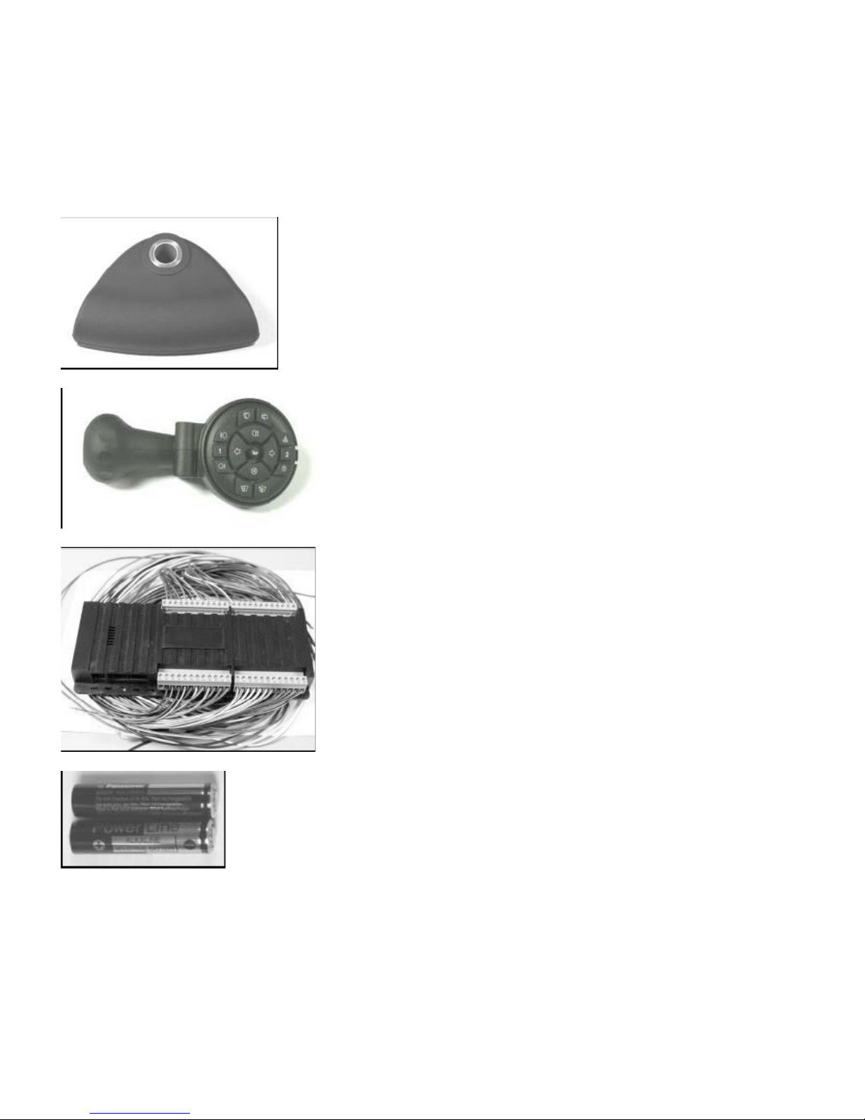
The kit consists of:
1 x steering wheel clamp
1 x transmitter steering ball assembly with RKS100 keypad
1 x RKS100 decoder relay box
2 x AAA Alkaline batteries
3 x 13mm screws 4 for mounting transmitter to a mounting plate
1 x customer information
1 x wiring instructions for particular vehicle
1 x interface box (only if required for particular vehicle in the wiring instructions above)
1 x additional parts (only if required for particular vehicle in the wiring instructions above)
Pg. 1
LogiTouch Installation & Setup Instructions, Ver. 2008
Transmitter Keypad:
The transmitter keypad is battery powered, and the batteries will last 2-3 years with average use. The maximum operating range in free air is
approximately 20 yards. Each one has its own unique ID code so there is no danger of operating another vehicle accidentally. There is a low battery
indicator which also indicates if the transmitter is being received by the relay box. If it goes out the instant a pressed button is released, it is working.
If it stays on for about half a second, then the transmitter is not in communication with the relay box.
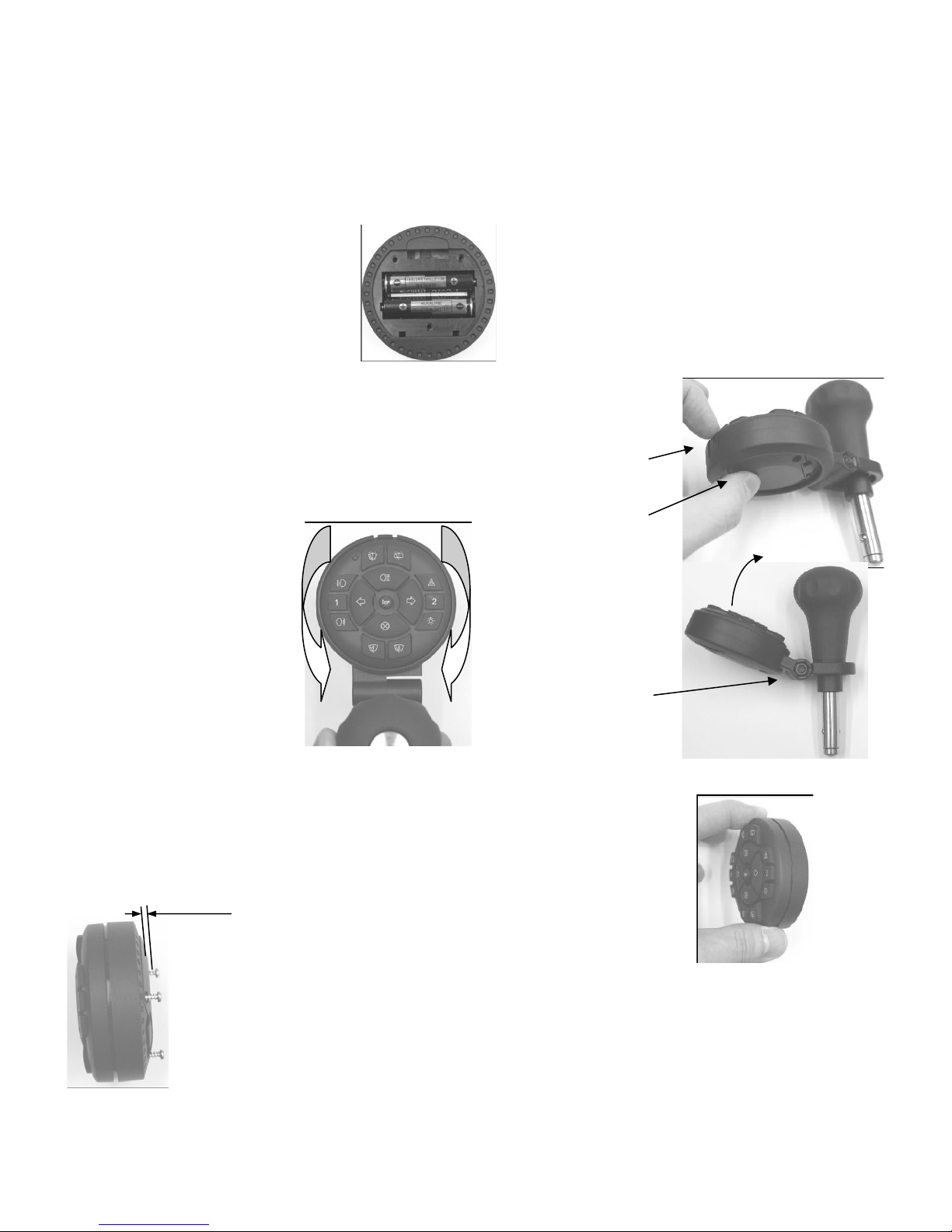
Battery installation:
Use alkaline AAA batteries ONLY, not rechargeable batteries or any other type.
The batteries are installed as shown:
Refit the 3 battery cover screws.
Methods of use:
1. Attached to the steering wheel using the transmitter ball assembly & clamp
(supplied in kit):
The transmitter can be adjusted at any rotary angle required by the user. The keypad is supplied pushed into
the mounting ring. CAREFULLY remove it by pushing up the keypad and pulling on the locking tab:
Locate the keypad in the ring at the
required angle.
Note it may need to rotate slightly to
line up with the locking pins
underneath.
Push into locking ring and make
sure it is securely locked in position.
2. Used on its own:
The keypad can be hand-held and used anywhere in the vehicle. It does not need to be
in line of sight with the decoder or any receiver and can be used anywhere.
3 Attached to a flat surface:
For a mounting plate of
.039 - 118” (20-12Ga.)
thickness only.
Carefully pull on tab
to release transmitter
Push here
The angle of the keypad
face can also be adjusted.
Undo the locking bolt and
adjust as required, then
retighten.
The keypad can be fixed to a plate by using the longer screws supplied in the kit.
These are intended for a mounting plate .039 - 118” thick.
Do not use any screws other than the ones supplied.
Do not use the longer screws to hold the battery cover in place, otherwise, the transmitter will be damaged.
Alternatively, Velcro or double sided tape may be used.
Pg. 2
 Loading...