

Page 1
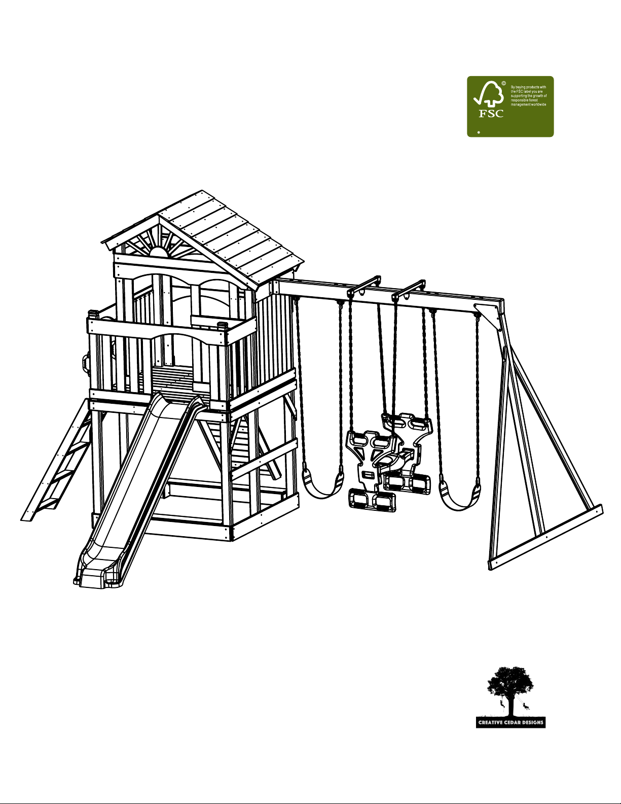
Owner's Manual
And
Assembly Instructions
SGS- COC-00531 0
1996 For est Steward ship Counc il A.C.
For FS C certi fied produc ts
look f or the FS C label
Timber Valley
Model: 3512
Page 2
Thank you for purchasing a
Creative Cedar Designs
Playcenter. We hope it will
bring you and your children
many years of safe and
enjoyable backyard fun.
Table of Contents
Letter to Customer 2
Positioning Your Playcenter
Tools Required for Assembly
Helpful Installation Hints
Suggested Playground Surfacing
Operating Instructions
Maintenance Instructions
Disposal Instructions
CPSC Information Sheet
Assembly Instructions
Limited Warranty
Warranty Claim Procedure
Customer Registration Card
3
3
4
5
6
7
7
8
9
42
43
44
Your owner’s manual should be read carefully
before starting assembly.
Page 3

STOP…PLEASE READ!!
IF YOU HAVE ANY QUESTION OR ARE
MISSING A PART, PLEASE DO NOT CONTACT
THE RETAILER THAT YOU PURCHASED THIS
PRODUCT FROM. PLEASE VISIT
www.creativecedardesigns.com
OR CONTACT US DIRECTLY
AT OUR OFFICE, 1-888-363-4967
WE WILL ANSWER YOUR
QUESTIONS,
OR HELP WITH WHAT YOU NEED.
For more efficient service, please log onto
our website at
www.creativecedardesigns.com
and fill out a request for missing or damaged parts.
A completed product registration is also necessary
for all warranty claims.
For all international customers, please visit the following website for information on all warranty
issues including where to obtain replacement parts.
www.creativecedardesigns.com
1
Page 4
Dear Customer:
Thank you for purchasing a Creative Cedar Designs Playcenter. We hope it will bring you
and your children many years of safe and enjoyable fun. Creative Cedar Designs equipment
is recommended for use by children 3 to 10 years of age. Creative Cedar Designs structures
are not intended for public use. Creative Cedar Designs does not warranty any of its
residential structures subjected to commercial use.
WARNING: This symbol points out important safety instructions which, if
not followed, could endanger the personal safety of yourself and your
children and/or damage your property. You MUST read and follow all
instructions in this manual before attempting to use this playcenter.
WARNING: Children must NOT use this playcenter until unit has been
completely assembled and inspected by an adult to insure set has been
properly installed.
Please follow all recommendations below. Failure to do so may result in the warranty
being void and/or safety violations that could result in serious injury. The following
information has been provided to help you in your installation, continued satisfaction, and
safe operation of your Creative Cedar Designs purchase.
Always keep the safety of your children in mind as your play structure is being built and
as your children play on the set. Before your children play on the set please review the
Operation Instructions with them to help ensure their safety.
PLEASE RETAIN THESE INSTRUCTIONS FOR FUTURE REFERENCE.
KEEP THEM IN A SAFE PLACE WHERE YOU CAN REFER TO THEM AS
NEEDED. IN ORDER TO PROVIDE YOU WITH THE MOST EFFICIENT
SERVICE, IT IS REQUIRED THAT YOU PROVIDE US WITH THE PART
NUMBERS WHEN ORDERING PARTS.
Please do NOT return the playcenter to the retailer from which it was purchased,
without first contacting Customer Service.
General Information:
Please take time and fill out the information below. This information will be needed for
warranty issues.
Date of Purchase:_______________ Date stamped on box:______________
Manufacturer:
Creative Cedar Designs
PO Box 4901
Chattanooga, TN 37405
E-mail: [email protected]
Website: www.creativecedardesigns.com
Retailer
______________________
:
_________________
______________________
Unit Type:
Unit Name: Timber Valley Play Sete: Revision Date: 12/13/2020
Unit Model Number: 3512
Maximum Fall Height: 6'-5"
2
Page 5
The instructions and owner’s manual for your new Playcenter should be read in its
entirety before assembly, to minimize problems and safety issues. We recommend
reading the owner’s manual thoroughly after you have identified all of the parts for your
Playcenter as discussed in the Helpful Installations Hints section below.
Positioning Your Play center
1. The Playcenter is designed to be installed on a level surface by an Adult with an Adult
helper. Try to place in a flat area of your yard to minimize ground preparation.
2. Choose a level location for the equipment. This can reduce the likelihood of the play set
tipping over and loose-fill surfacing material washing away during heavy rains.
3. Place the equipment not less than 6 ft from any structure or obstruction such as a fence,
garage, house, overhanging branches, laundry lines, or electrical wires.
4. Provide enough room so that the children can use the equipment safely. For example, for
structures with multiple play activities, a slide should not exit in front of a swing.
5. It is a good idea to place your Playcenter in an area that is convenient for adults to watch
children
6. Create a site free of obstacles that could cause injuries – such as low overhanging tree
branches, overhead wires, tree stumps and/or roots, large rocks, bricks and concrete. We
have additional suggestions in the Suggested Playground Surfacing Section.
7. Do not build your playset on top of surfacing material.
8. Locate bare metal platforms and slides out of direct sunlight to reduce the likelihood of
serious burns. A slide that faces north will receive the least direct sunlight.
9. Separate active and quiet activities from each other. For example, locate sandboxes away
from swings or use a guardrail or barrier to separate the sandbox from the movement of
the swings.
at play.
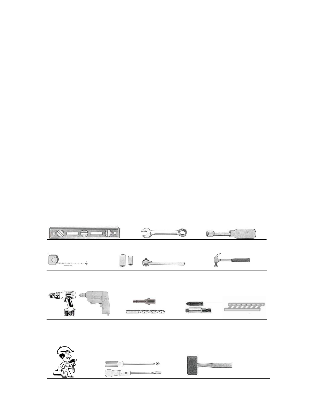
Tools Required for Installation:
(These are the tools that are generally required for assembly of our playsets. These tools are not included in the playset purc hase.)
Level 24”
Tape Measure
3/8” Drill
3/8” Drive Ratchet, (1/2” & 9/16”)
Std Socket & Deep Well
(1/8”, 5/16” & 3/8”)
Open End Wrenches
(7/16” & 1/2”)
Drill Bits
Claw Hammer
Drill attachments
(3/8” Socket Driver
Torque head screw)
Nut Drivers
(1/2” & 9/16”)
Ladder
An Adult w/an
Adult helper
Screw Drivers
(Phillips & Straight)
Rubber Mallet (Optional)
3
Page 6

Helpful Installation Hints
1. Depending on your experience, assembly of this Play set should take
approximately 6 to 12 hours after inventory of parts. Therefore, we recommend
you set aside a full day for assembly.
2. Identify all of the parts for your Playcenter. Empty each box and lay out boards
so you can see each part. Your instruction book will have detailed drawings that
will make it easy for you to recognize individual parts. Keep all hardware and
metal parts separate from wooden pieces.
3. After everything is laid out, check carefully to ensure all parts are present. Make
sure there are no broken boards.
4. Find an area to sort your hardware. It is best to open the hardware on a solid
surface so that you do not lose any pieces in the grass. This will save time and
familiarize you with all the different pieces in the hardware bag.
5. Important note: Wood has some natural defects such as knots, surface cracks,
etc… We reject parts that are structurally defective. We use a high quality
lumber in our structures; however, you should inspect each part for splinters or
rough spots and sand them smooth to prevent injury.
6. After steps 1 thru 4 have been completed, read all the way through the
instructions completely. Reading instructions after you have studied the parts will
help you understand more clearly the installation process, and help to eliminate
unnecessary mistakes.
7. Pay close attention to the diameter and length of each bolt and screw.
8. Swing hangers should be buried past the threads, so that the loop is against the
swing beam. Creative Cedar Designs is not responsible for incorrect installations of
swing hangers. Failure to properly install swing hangers may cause severe injury.
9. Never tighten hardware completely at first. It helps to have some adjustment for
bolt alignment while you are attaching parts together. After everything is square,
tighten each joint.
10. After the main unit is assembled it is critical that the floor is level and square. If
the main frame is not level, the walls and floor will be out of square.
11. After you complete installation, make sure every bolt, screw, and nut is tight, and
every board is secure. Wood will expand and contract with the seasons. Check
all bolt connections and swing hangers every two weeks.
12. Place the set on level ground, not less than 6ft from any structure or obstruction
such as a fence, garage, house, overhanging branches, laundry lines, or electrical
wires.
READ! VERY IMPORTANT!
If you are missing parts or have questions regarding the installation of our quality product PLEASE call us
directly at our offices (1-888-363-4967). Our trained staff will be happy to assist you.
Customer service hours:
Monday thru Friday 9am to 4pm
Eastern Standard Time.
E-mail: [email protected]
4
Page 7

Suggested Playground Surfacing
Playground equipment should never be placed on hard surfaces such as concrete
or asphalt.
Do not install loose fill surfacing over hard surfaces such as concrete or asphalt.
Shredded bark mulch, wood chips, fine sand and fine gravel, are added as shock
absorbing materials after assembly. If used properly these materials can absorb
some of the impact of a child’s fall.
All surface material should extend a minimum of 6 feet in all directions around
the play area.
Do not apply playground surfacing until after the unit is completely constructed.
Playset should not
Use containment, such as digging out around the perimeter and/or lining the
perimeter with landscape edging.
Installation of rubber tiles or poured-in-place surfaces (other than loose-fill
materials) generally require a professional and are not “do-it-yourself” projects.
Shall use Playground Surfacing Materials (other than loose-fill material) which
comply to the safety standard ASTM F1292 Standard Specification of Impact
Attenuation of Surfacing Materials within the Use Zone of Playground
Equipment.
be built on top of surfacing.
The following chart explains the fall height in feet from which a life threatening
head injury would not be expected
Critical Heights in feet (m) of Tested Materials
Material Uncompressed Depth Compressed Depth
6" (152mm) 9" (228mm) 12" (304mm) to 9" (228mm)
Wood Chips 7' (2.13m) 10' (3.05m) 11' (3.35m) 10' (3.05m)
Double-Shredded bark mulch 6' (1.83m) 10' (3.05m) 11' (3.35m) 7' (2.13m)
Engineered Wood Fibers 6' (1.83m) 7' (2.13m) >12' (3.66m) 6' (1.83m)
Fine Sand 5' (1.52m) 5' (1.52m) 9' (2.74m) 5' (1.52m)
Coarse Sand 5' (1.52m) 5' (1.52m) 6' (1.83m) 4' (1.22m)
Fine Gravel 5' (1.52m) 7' (2.13m) 10' (3.05m) 6' (1.83m)
Medium Gravel 5' (1.52m) 5' (1.52m) 6' (1.83m) 5' (1.52m)
Shredded Tires* 10-12' (3.0-3.6m) N/A N/A N/A
*This data is from tests conducted by independent testing laboratories on a 6-inch depth of uncompressed shredded tire samples
produced by four manufacturers. The tests reported critical heights, which varied from 10 feet to greater than 12 feet. It is
recommended that persons seeking to install shredded tires as a protective surface request test data from the supplier showing the
critical height of the material when it was tested in accordance with ASTM F1292.
5
Page 8

Operating Instructions:
NOTE: Your children’s safety is our #1 concern. Observing the
following statements and warnings reduces the likelihood of serious or
fatal injury. Please review these safety rules regularly with your
children.
1. This Playcenter is designed for the use of 6 occupants,
weight not exceeding
combined
who have a combined
(this weight is not including the sand box area)
2. On-site adult supervision is required.
3. Instruct children not to walk close to, in front of, behind, or between moving
swings or other moving playground equipment.
4. Instruct children to sit in and never stand on swings
5. Instruct children not to twist the chains and ropes and not to loop them over the
top support bar, since this may reduce the strength of the chain or rope.
6. Instruct children not to jump from swings or other playground equipment in
motion.
7. Instruct children to not push empty seats. The seat may hit them and cause
serious injury.
8. Instruct and teach children to sit in the center of the swings with their full weight
on the seats.
9. Instruct children not to use the equipment in a manner other than intended.
10. Instruct children to always go down slides feet first. Never slide headfirst.
11. Instruct children to look before they slide to make sure no one is at the bottom.
12. Instruct children to never run up a slide, as this increases their chances of falling.
13. The parents should have the children dress appropriately with well-fitting shoes.
Loose clothing such as scarves and ponchos should not be worn. Always take off,
tie up or tuck in cords and drawstrings on children’s clothing. These things can
get caught on playground equipment and strangle a child.
14. Instruct children not to climb when the equipment is wet.
15. Instruct children to never jump from a fort deck. They should always use the
ladder, ramp or slide.
16. Instruct children to never crawl on top of a fort roof.
17. Verify that any suspended climbing ropes, chain, or cable are secured at both ends
and that they cannot be looped back on it.
18. Instruct children not to attach items to the playground equipment that are not
specifically designed for use with the equipment, such as, but not limited to, jump
ropes, clothesline, pet leashes, cables, and chain as they may cause a strangulation
hazard.
19. Instruct children to never wrap their legs around swing chain.
20. Instruct children to never slide down the swing chain.
weight of
420 pounds,
350 pounds
weight of
total
4 occupants on the swing area, who have a
,
for a total unit cpacity of 10 occupants who
770 pounds.
who have a combined
6
Page 9

Maintenance Instructions:
1. Check all nuts and bolts twice monthly during the usage season and tighten as required. (But
not so tight that you crack the wood) We recommend you check the swing beam and
hardware every two weeks due to wood expansion and contraction. It is particularly
important that this procedure be followed at the beginning of each season.
2. Remove plastic swing seats and take indoors or do not use when the temperature drops below
32
F.
3. Oil all metallic moving parts monthly during the usage period.
4. Check all coverings for bolts and sharp edges twice monthly during usage season to be certain
they are in place. Replace when necessary. It is especially important to do this at the
beginning of each new season.
5. Check swing seats, ropes, cables and chains monthly during usage season for evidence of
deterioration. Replacement should be made of any swing seat that has developed cracks in
the plastic seats or has exposed metal in the edges of the swing seat. If there are already
exposed metal inserts on the edge of the seat, immediately remove the seats and chains to
prevent serious injury. Ropes, cables and chains should be removed and replaced if excessive
wear is found. Contact Creative Cedar Designs for replacement parts.
6. For rusted areas on metallic members such as monkey bars, hand supports, brackets, etc.,
sand and repaint, using a non lead-based paint meeting the requirements of Title 16
1303.
7. Inspect wood parts monthly. The grain of the wood sometimes will lift in the dry season
causing splinters to appear. Light sanding may be necessary to maintain a safe playing
environment. If you are treating your Playcenter with stain regularly, it will help prevent
severe checking/splitting and other weather damage.
8. We have applied a waterborne transparent stain to your unit. This is done for color only.
Once or twice a year, depending on your climate conditions, you must apply some type of
protection (sealant) to the wood of your unit. Prior to the application of sealant, lightly sand
any “rough” spots on your set. Please note this is a requirement of your warranty.
9. Creating and maintaining the Playcenter on a level location is very important. As your
children play, your Playcenter will slowly dig its way into the soil, and it is very important
that it settles evenly. Make sure the play set is level and true
beginning of each play season.
once each year or at the
10. Rake the surface periodically to prevent compaction and maintain appropriate depths.
CRF Part
Disposal Instructions:
When the Playcenter use is no longer desired, it should be disassembled and disposed of in such a
way that no unreasonable hazards will exist at the time the unit is discarded.
7
Page 10

APPENDIX A
Information on Playground Surfacing Materials:
The following information is from the United States Consumer Product Safety
Commission’s Information Sheet for playground surfacing material Also see the
following website for additional information: https://www.cpsc.gov/PageFiles/122146/324.pdf
8
Page 11
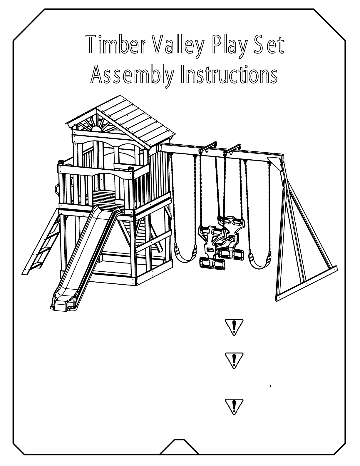
Timber Valley Play S et
Assembly Instructions
9
WARNING: CHOKING HAZARD
Unassembled parts may be a choking
hazard to children 3 years and
younger
CAUTION: Adult Assembly Required.
Hardware contains small pieces with
sharp points. Keep parts out of the
reach of children until assembled.
Parts of this product can present
dangers i
CAUTION: The plastic bags that contain
the hardware may present a choking
hazard to small children. Please keep
these bags and all plastic bags out of
the reach of children. Do not allow
children to play with them and dispose
of them immediately when empty.
mproperly assembled.
Page 12
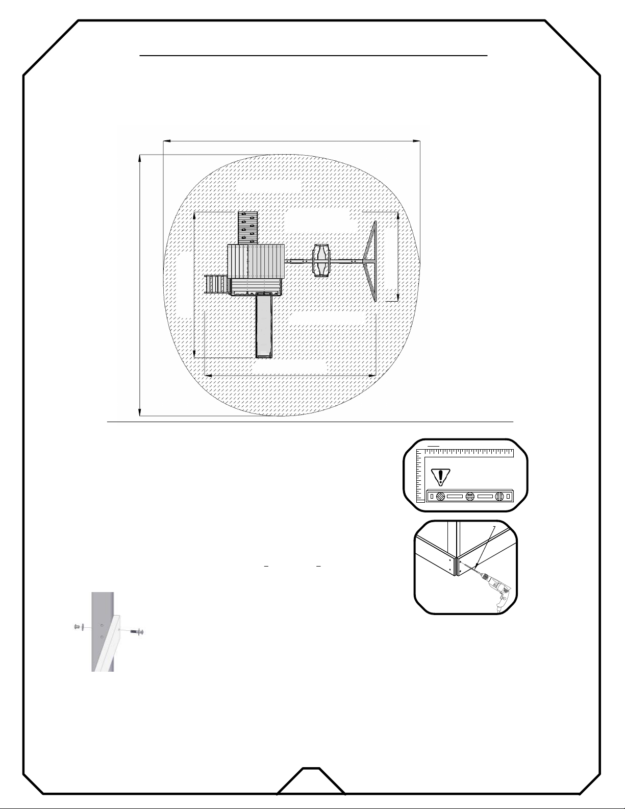
Basic Setup Dimen sions
Place the set on level ground, not less than 6ft (1.83M) from any structure or
obstruction such as a fence, garage, house, overhanging branches, laundry lines or
electrical wires.
27'-7"
SAFETY AREA
SAFE HEIGHT
Ht=15'-3"
7'-9"
25'-7"
14’
Ht=9'-3"
16’
Important Assembly Notes
1) While assembling unit, take time before and after each phase
to make sure Fort is level. If fort is not level, assembly will be
difficult and improper assembly may result. Extra care must
be taken to assure the fort is square on the phases that
include this symbol in Fig i.
2) When installing a board on the small face of a 2x4, pre-drilling
the attachment hole is REQUIRED. Just place the board where
attachment is needed and by using the holes in the board as a
guide, drill holes into the 2x4 with a
Failure to Pre-drill may result in board splitting
3) Whenever a T-nut is used, follow these directions. Place t-nut in pre-drilled
hole. Tap in with hammer. Place bolt with split and flat washers in the]
opposite side. Hand tighten to make sure the bolt is in the t-nut. Secure
with socket. DO NOT Over Tighten.
1
" drill bit 1
8
1
" deep.
4
Fig. i
Note: It is vi tal that the fort
be level before and
after this phase!
1/8" Drill Bit
4) Pay close attention to the "Items needed" and "Hardware needed" sections of each phase. They can
be a valuable aid when sorting your wood and hardware. Assembly will be made easier if items are
sorted by phase.
5) Pay close attention to make sure you are using the correct hardware in the correct places. Using
incorrect hardware may result in improper assembly.
6) Read the steps of each phase thoroughly. The written steps may include important information not
shown in the illustrations.
10
Page 13
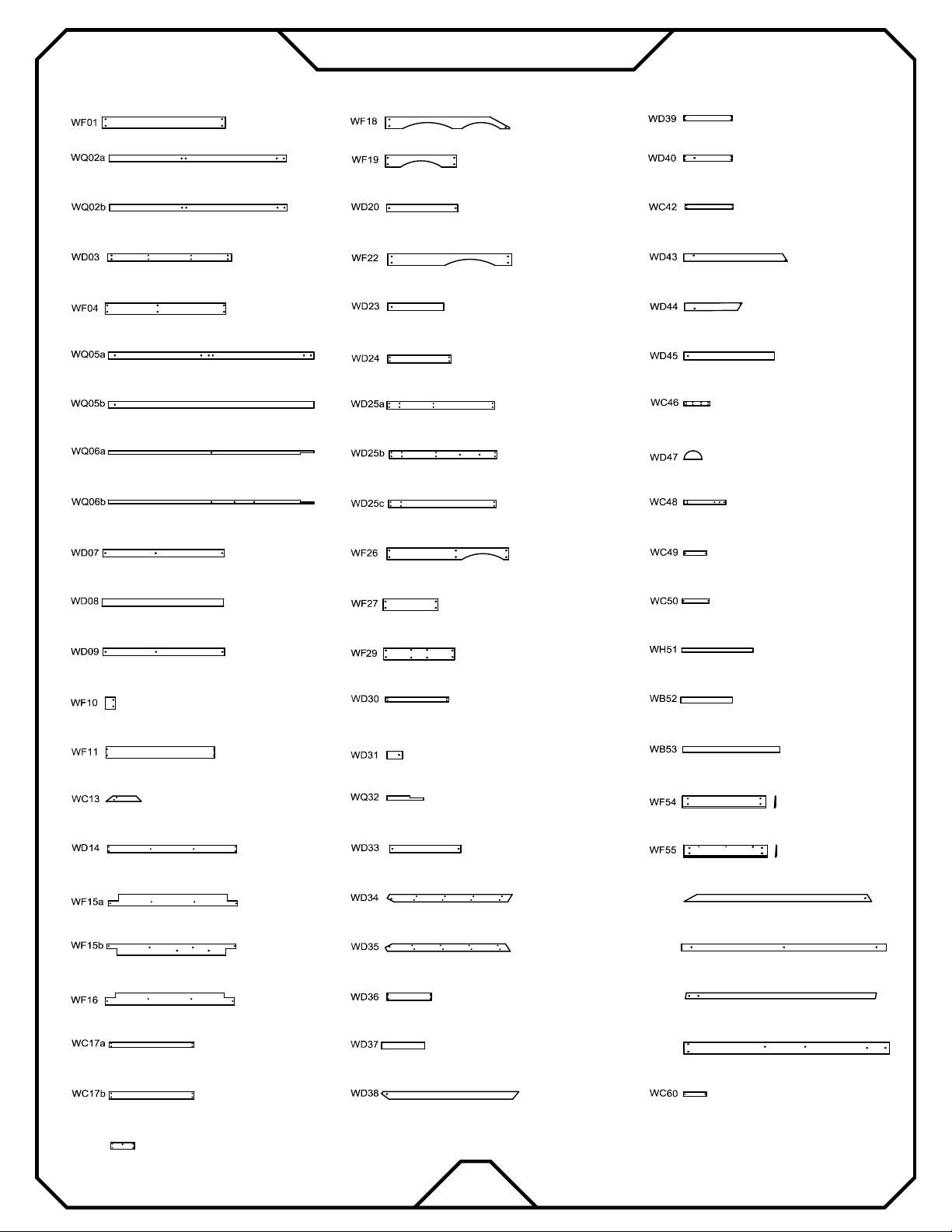
Parts Identification
Wood Components
(2) Sanbox board-A 1×6×54
(1) Upringt-A 3×4×78 3/4
(1) Upright-B 3×4×78 3/4
(2) End Floor Support 5/4×4×54
(2) Sandbox Board-B 1×6×52 13/16
(1) Upright-C 3×4×89 5/16
(1) Upright-D 3×4×89 5/16
(1) Upright-E 3×4×89
(1) Upright-F 3×4×89
(2) Floor Joist 5/4×4×52 13/16
(2) Top Double Arch Board 1×6×54
(1) Top Arch Board 1×6×31
(1) Top Brace 1×4×31
(2) Playhouse Arched Guardrail-A 1×6×54
(4) Tower Surrounded Board 1×4×24 3/8
(25) Playhouse Wall Slat-A 1×4×27 9/16
(1) Playhouse Wall Slat-B 1×4×46 3/4
(2) Playhouse Wall Slat-C 1×4×46 3/4
(1) Playhouse Wall Slat-E 1×4×46 3/4
(1) Playhouse Arched Guardrail-B 1×6×52 13/16
(8) Rock Board-A 1×4×21
(8) Rock Board-B 1×4×21
(1) Rock Board-C 1×3×21
(2) Sunburst Frame-A 1×4×45
(2) Sunburst Frame-B 1×4×25
(2) Sunburst Frame-C 1×4×45 7/16
(2) Roof Brace Fixed 1×3×11 7/16
(2) Sunburst DecoBoard 1×4×4 7/8
(2) Sunburst Trim-A 1×2×18 5/16
(4) Sunburst Trim-B 1×3×9 27/32
(2) Floor Support 1×4×52 3/4
(2) First Floor Guardrail 1×4×52 13/16
(4) Sandpit Seat Support 1×6×4 1/2
(2) Sandbox Seat 1×6×47 1/4
(4) Platform Support 1×3×15 5/16
(11) Floor Board-A 1×4×56 1/8
(1) Floor Board-B 1× 4×56 1/8
(1) Floor Board -C 1× 4×56 1/8
(1) Floor Board-D 1×6×56 1/8
(1) Wall Slat-A 1×3×37
(1) Gazebo Guardrail 1×6×23 29/32
(1) Swing Attaced Board 5/4×6×31
(1) Playhouse Wall Slat-D 1×3×27 9/16
(3) Tower Surrounded Board-C 1×4×6 27/32
(2) Upright-G 3×4×15 29/32
(1) Tower Surrounded Board-D 1×4×31
(1) Ladder Rail(Left) 5/4×4×54 3/8
(1) Ladder Rail(Right) 5/4×4×54 3/8
(4) Ladder Step 1×6×23 29/32
(1) Ladder Block 1×4×20
(4) Sunburst Trim-C 1×3×11 13/16
(1) Roof Beam-A 2×2×31
(1) Roof Beam-B 1×2×19 7/8
(1) Roof Beam-C 1×2×40 15/16
(12) Roof Board-A 1×6×36 5/16
(2) Roof Board-B 1×6×36 5/16
LG 252
(2) Swing Leg-A 2×4×82 1/2
LG 253
(1) Swing Ground Support 2×4×89
LD 254
(1) Swing Leg-B 3×4×83
LA 251
(1) Swing Beam 4×6×89 1/2
(7) Wall Slat-B 1×4×37
WD116
(2) Slide Support Board 11/16 X 3 1/2 X 12
(2) Rockwall Rail 5/4×4×59 3/4
11
(4) Sunburst Trim-D 1×3×13
Page 14
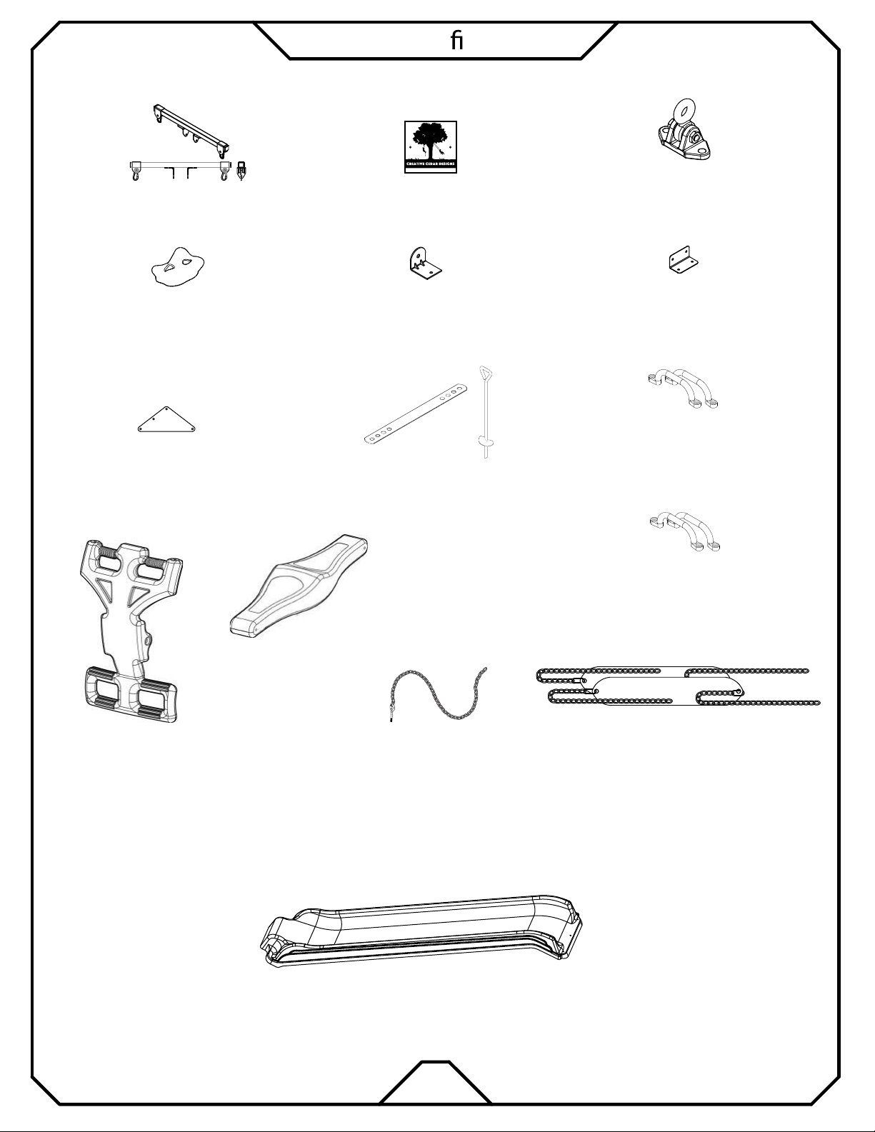
Parts Identi cation
Accessories
(1 - PAIR) GLIDER SUPPORT ASSEMBLY - BP020
(2) 4 COUNT BAGS CLIMBING ROCKS
BP011-GYBR w/ HARDWARE
(2) 100° TRIANGLE PLATE - M100
CreativeCedarDesigns.com
(1) ID-TAG
w/ HARDWARE
(14) GREEN L-BRACKET
M003
(2) ANCHOR 4-PACK
BP001-B
w/ HARDWARE
(4) SWING HANGER
KC 003
w/ HARDWARE
(2) GREEN ANGLE BRACKET
M005
(1 - PAIR) SAFETY HANDLE
w/ WOOD SCREWS
BP 007-Y
(1 - PAIR) SAFETY HANDLE
w/ T-NUTS
BP 007T-Y
(2) GLIDER ARM
(1) GLIDER SEAT
(1) GLIDER - BP 018-GY
w/ HARDWARE
(4) CHAIN w/ EYE BOLT
(1) 8’ SLIDE
(2) ULTIMATE SWING SEAT
BP014-Y
12
Page 15

Hardware Identi cation
a2
a3
a4
a1
(4)
(8)
(422)
(66)
2 1/2" Wood Screws
1 3/4" Wood Screws
#6DS3/4
1 1/8" Wood Screws
#6DS3/4
7/8" Wood Screws
#6DS3/4
5/16"×3 1/2" Hex Head Screws
#8DS3/4
e3
e5
e6
e8
5/16"×4 1/4" Hex-Head Bolt
(8)
5/16"×2 3/4" Hex-Head Bolt
(8)
5/16"×2 1/2" Hex-Head Bolt
(18)
5/16"×1 3/4" Hex-Head Bolt
(2)
b1
b2
(2)
(65)
c2
5/16 x 1 3/4 Hex Head Screws
1 Truss Head Screws
(7)
5/8" Tapping Screws
(20)
14#
e9
5/16"×1" Hex-Head Bolt
(6)
1/4 x 2 Button Head Bolts
(2)
13
Page 16
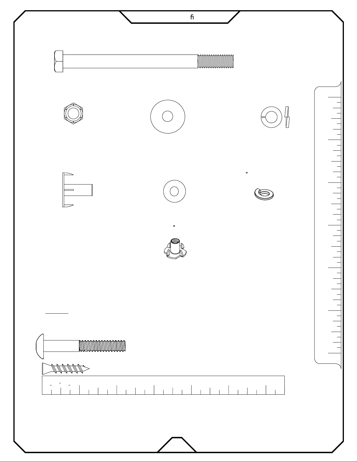
Hardware Identi cation
(7)
f3
5/16" Lock Nuts
g
(6)
(43)
h
5/16" x 4" Hex Bolts
LN5/16
5/16" T-nuts
5/16TN
5/16HB4
k2
5/16" Fender Washer
(122)
1/4" Flat Washers
(8)
k4
5/16FWX25
1/4FWX13
5/16" Split Washers
m
(43)
1/4 Lock Washer
(2)
0
1/4"
1/2"
3/4"
1"
2"
1/4 T-Nut
(2)
Measuring hardware
It is very important that you get the right hardware in the correct place when assembling the
unit. You can compare the hardware to the hardware identification page.
NOTES:
1) Do not include bolt head when measuring length of bolt.
2) Include full length of deck screw when measuring.
1
1
2
"
4
1"
"
3
"
4
2"
3"
4"
5" 6"
3"
4"
5"
6"
14
Page 17

FRONT
Quick Overview of Parts
RIGHT
15
Page 18

Quick Overview of Parts
LG252
LD254
LA251
LG253
BACK
16
LEFT
Page 19
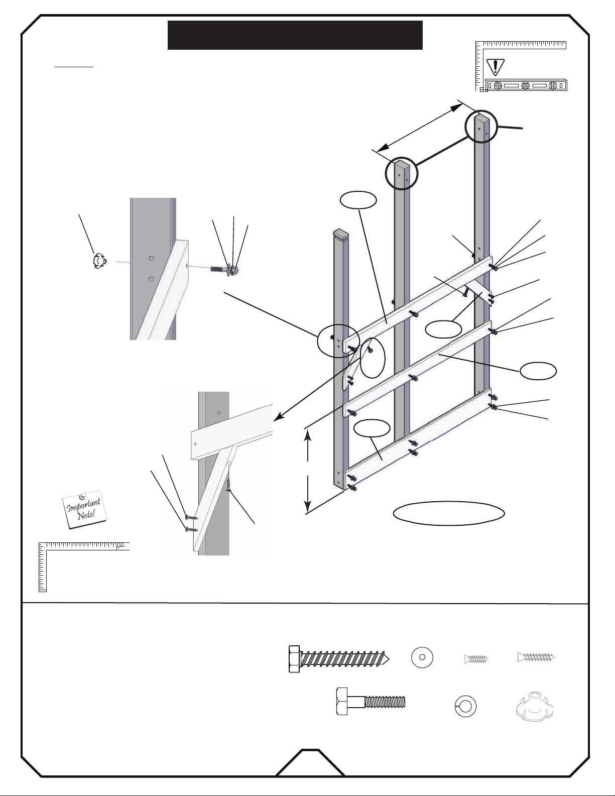
TOWER ASSEMBLY
S T E P :
* Insert all T-Nuts "h" into the uprights respectfully.
* Lay out WQ02a, WQ05b and WQ05a as shown.
* Attach WD07 into the pre-drilled holes with bolt "e3".
* Attach WD04 into the pre-drilled holes with wood screws "b2".
* Attach WD09 between WD07 and WD04 with wood
* Attach both WC13 as shown.
1
screws "b2".
h
k2
m
e3
WD07
WQ02a
WQ06a
30 7/8"
WQ05b
a1
h
WC13
Note: It is vital that the fort
be level after this
phase!
NOTE HOLE
LOCATIONS
WQ05a
k2
m
e3
a3
k2
b2
a3
a3
MAKE SURE FRAME IS
SQUARE BEFORE
PROCEEDING TO
NEXT PHASE!
ITEMS NEEDED
(1) WQ02a Upright-A 3×4×78 3/4
(1) WF04 Sandbox Board-B 1×6×52 13/16
(1) WQ05a Upright-C 3×4×89 5/16
(1) WQ05b Upright-D 3×4×89 5/16
(1) WD07 Floor Joist 5/4×4×52 13/16
(1) WD09 First Floor Guardrail 1×4×52 13/16
(2) WC13 Platform Support 1×3×15 5/16
a1
b2
26"
e3
(9)
WF04
Right wall of tower
HARDWARE NEEDED
k2
a3
(12)
m
(3)
(3)
(4)
WD09
k2
b2
a1
(2)
h
(3)
17
Page 20
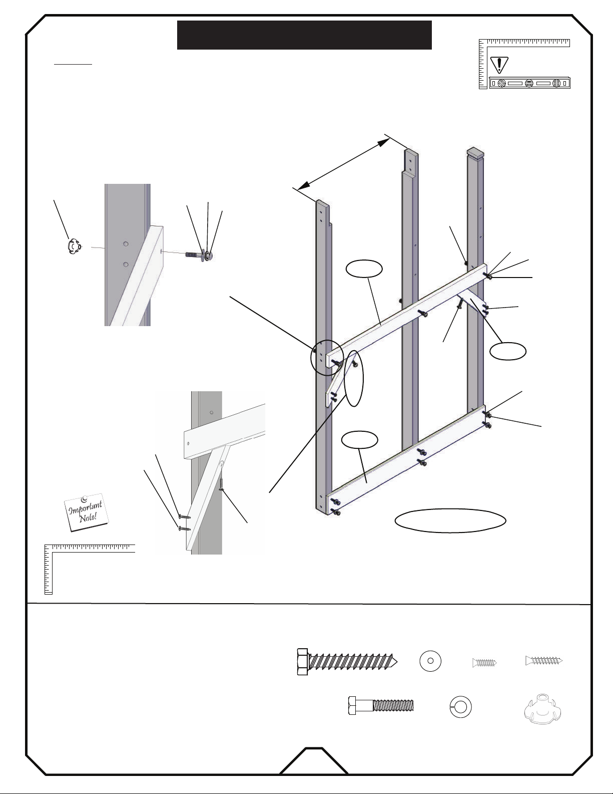
S TE P :
2
TOWER ASSEMBLY
* Insert all T-Nuts "h" into the uprights respectfully.
* Lay out WQ06a, WQ06b and WQ02b as shown.
* Attach WD07 into the pre-drilled holes with bolts "e3".
* Attach WF04 into the pre-drilled holes with wood screws "b2".
* Attach both WC13 as shown.
30 7/8"
Note: It is vital that the fort
be level after this
phase!
h
k2
m
e3
WQ06b
h
WQ02b
k2
WQ06a
WD07
m
e3
a3
a1
WC13
k2
b2
a3
WF04
a3
MAKE SURE FRAME IS
SQUARE BEFORE
PROCEEDING TO
NEXT PHASE!
ITEMS NEEDED
(1) WQ02b Upright-B 3×4×78 3/4
(1) WF04 Sandbox Board-B 1×6×52 13/16
(1) WD07 Floor Joist 5/4×4×52 13/16
(1) WQ06a Upright-E 3×4×89
(1) WQ06b Upright-F 3×4×89
(2) WC13 Platform Support 1×3×15 5/16
a1
b2
18
e3
(6)
Left wall of tower
HARDWARE NEEDED
k2
(3)
a3
(9)
m
(3)
(4)
46 9/16"
a1
(2)
h
(3)
Page 21
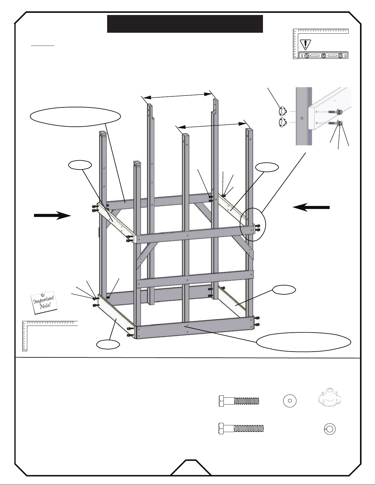
TOWER ASSEMBLY
S TE P :
* Insert all T-Nuts "h" into the uprights respectfully.
* Stand Right Wall from Step1 and Left Wall from Step2.
* Attach both WF01 to form the front and back bottom of the tower with bolts "e6".
* Attach both WD03 to form the front and back middle of the tower with bolts "e5".
3
30 7/8"
Note: It is vital that the fort
be level after this
phase!
h
Left Wall of tower from Step2
WD03
Front side of tower
k2
m
e6
30 7/8"
k2
h
k2
m
e5
WD03
m
e5
Back side of tower
h
WF01
FRONT
MAKE SURE FRAME IS
SQUARE BEFORE
PROCEEDING TO
NEXT PHASE!
WF01
ITEMS NEEDED
(2) WD03 End Floor Support 5/4×4×54
(2) WF01 Sanbox board-A 1×6×54
19
e6
e5
Right Wall of tower from Step1
HARDWARE NEEDED
k2
(8)
(8)
(16)
h
(16)
m
(16)
Page 22

TOWER ASSEMBLY
4S TE P :
* Attach both WD08 with wood screws "a2".
* Install four "L" brackets (M003) with wood screws "c2".
a2
WD08
Note: It is vital that the fort
be level after this
phase!
a2
a2
c2
WD03
c2
M003
a2
a2
a2
c2
WD03
MAKE SURE FRAME IS
SQUARE BEFORE
PROCEEDING TO
NEXT PHASE!
ITEMS NEEDED
(2) WD08 Floor Support 1×4×52 3/4
(4)
M003
20
HARDWARE NEEDED
c2
(8)
a2
(8)
Page 23
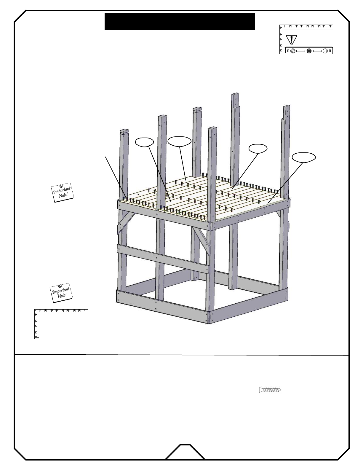
TOWER ASSEMBLY
5S TE P :
* Lay WF15a, WF15b, WF16 in its rightful place as shown.
* Lay all eleven WF14 in between to from the tower deck.
* Once all slats are in place, make sure all slats are flush on the left and right side of the tower.
* Once all slats are are flush secure slats with wood screw "a3".
Note: It is vital that the fort
be level after this
phase!
a3
Make sure "a3" wood screws are
going into the suport below.
WD16
WD07
WD115b
WD14
WD15a
WD03
BACK
MAKE SURE FRAME IS
SQUARE BEFORE
PROCEEDING TO
NEXT PHASE!
ITEMS NEEDED
(11) WF14 Floor Board-A 1×4×56 1/8
(1) WF15a Floor Board-B 1× 4×56 1/8
(1) WF15b Floor Board -C 1× 4×56 1/8
(1) WF16 Floor Boardb-D 1×6×56 1/8
HARDWARE NEEDED
a3
(78)
21
Page 24
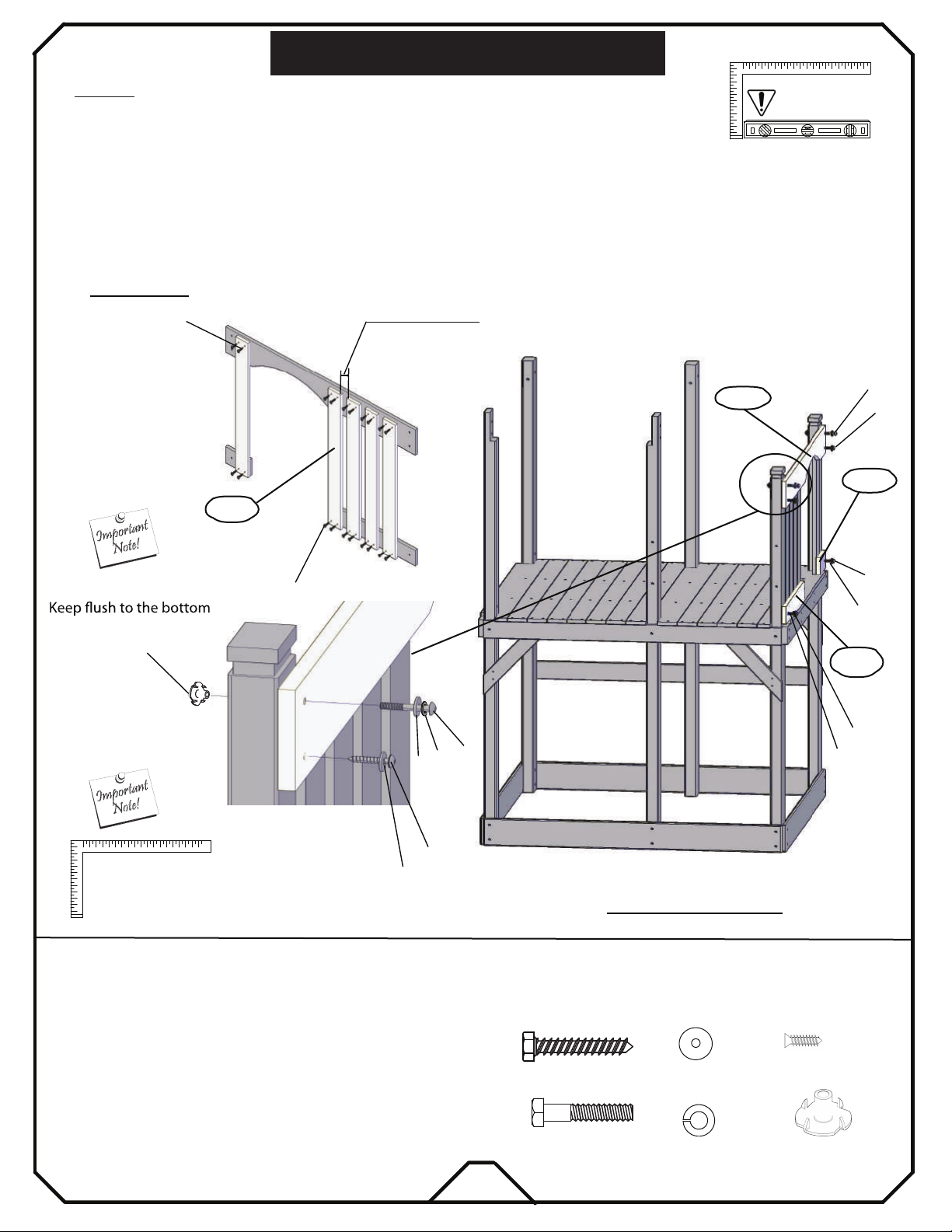
TOWER ASSEMBLY
6S TE P :
* Insert all T-Nuts "h" into the uprights respectfully.
* Attach WD23 and WD31 to WQ02a & b with wood screw "b2".
* Attach WF22 to WQ02a & b (See diagram below).
* From the inside deck, attach four WD24 to the right of the arch with wood screws "a3".
* From the inside deck, attach one WD24 to the left of the arch with wood screws "a3".
Inside view
a3
WD24
1 3/4"
Note spacing
Note: It is vital that the fort
be level after this
phase!
WF22
e6
b2
WD31
Note spacing 1 3/4"
a3
h
MAKE SURE FRAME IS
SQUARE BEFORE
PROCEEDING TO
NEXT PHASE!
k2
ITEMS NEEDED
(1) WF22 Playhouse Arched Guardrail-A 1×6×54
(1) WD23 Tower Surrounded Board 1×4×24 3/8
(1) WD31 Tower Surrounded Board-C 1×4×6 27/32
k2
b2
b2
k2
WD23
e6
m
FRONT
b2
k2
Front wall assembly
HARDWARE NEEDED
b2
(4)
k2
(6)
a3
(20)
(5) WD24 Playhouse Wall Slat-A 1×4×27 9/16
22
e6
(2)
m
(2)
h
(2)
Page 25
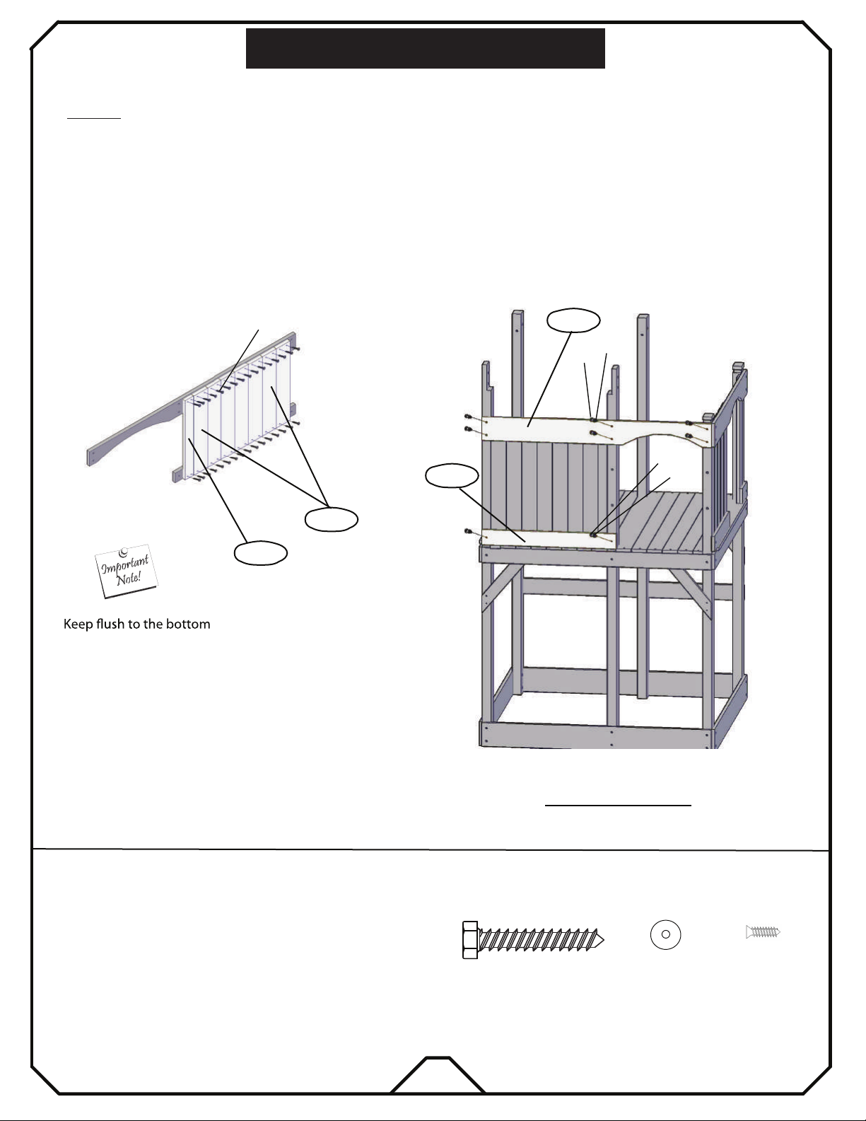
TOWER ASSEMBLY
7S TE P :
* Attach WD33 and WF26 with wood screws "b2".
* From the inside deck, attach WD30 to the right of the arch with wood screws "a3".
* From the inside deck, attach seven WD24 to the right of WD30 side by side with no spaces in between
with wood screws "a3".
a3
WD30
WD24
WD33
WF26
b2
k2
WF22
b2
k2
FRONT
ITEMS NEEDED
(1) WF26 Playhouse Arched Guardrail-B 1×6×52 13/16
(1) WD33 Tower Surrounded Board-D 1×4×31
(1) WD30 Playhouse Wall Slat-D 1×3×27 9/16
(7) WD24 Playhouse Wall Slat-A 1×4×27 9/16
b2
23
Left wall assembly
HARDWARE NEEDED
k2
(8)
(8)
a3
(32)
Page 26

TOWER ASSEMBLY
8S TE P :
* Insert T-Nuts “h" into the uprights respectfully.
* Attach the WD23 and WD31 to the uprights with bolts "e6".
* Attach WF22 to the uprights with wood screws "b2".
* From the inside deck, attach both WD25b, one on each side of the arch with wood screws "a3".
(There should be no spaces).
WF22
WD25b
a3
b2
k2
a3
WD24
WD23
WD31
Back
h
k2
m
e6
Back wall assembly
ITEMS NEEDED
(1) WF22 Playhouse Arched Guardrail-A 1×6×54
(1) WD23 Tower Surrounded Board 1×4×24 3/8
(1) WD31 Tower Surrounded Board-C 1×4×6 27/32
(5) WD24 Playhouse Wall Slat-A 1×4×27 9/16
(2) WD25b Playhouse Wall Slat-C 1×4×46 3/4
24
e6
b2
HARDWARE NEEDED
k2
(4)
(2)
(6)
m
(2)
a3
(28)
h
(2)
Page 27
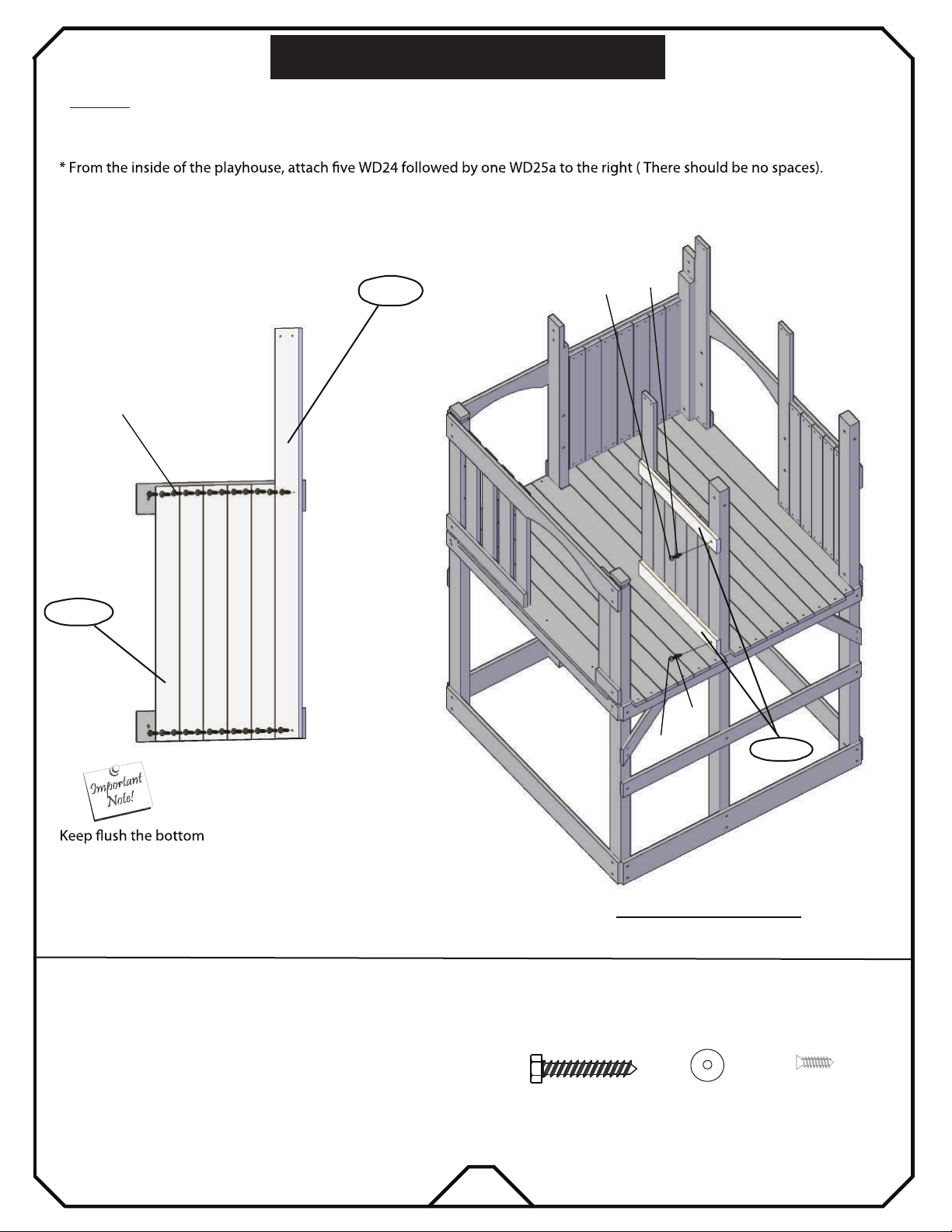
TOWER ASSEMBLY
9S TE P :
* Attach both WD23 with wood screws "b2".
a3
WD25a
k2
b2
WD24
ITEMS NEEDED
(2) WD23 Tower Surrounded Board 1×4×24 3/8
(5) WD24 Playhouse Wall Slat-A 1×4×27 9/16
(1) WD25a Playhouse Wall Slat-B 1×4×46 3/4
b2
k2
b2
Interior wall assembly
HARDWARE NEEDED
k2
(2)
(2)
WD23
a3
(24)
25
Page 28
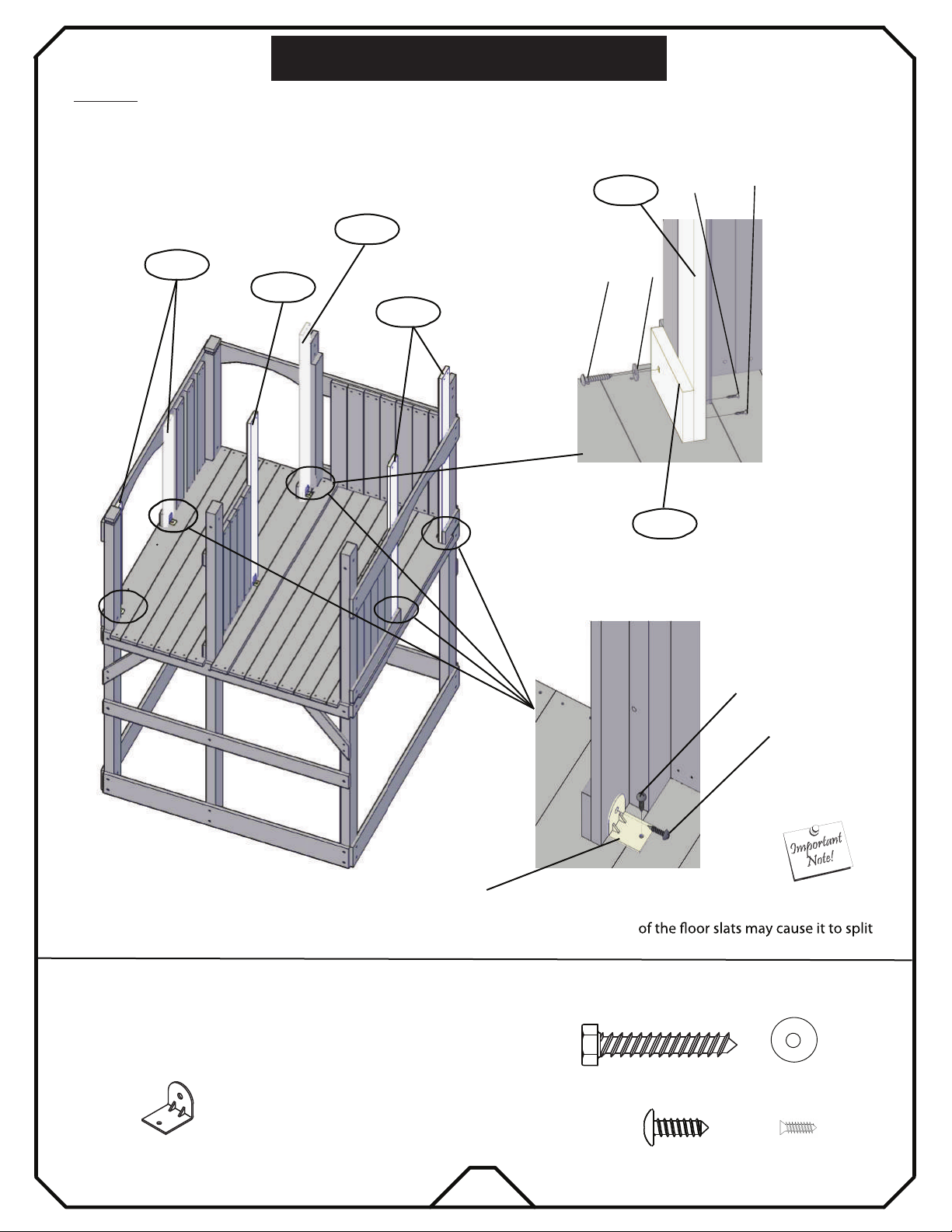
TOWER ASSEMBLY
:
10S TE P
* Attach WD31 with wood screws "b2" from the front .
* From the inside of the play house, attach WD25c with wood screws "a3".
* Install six L brackets "M003" as shown.
WD25c
a3
a3
WD24
WD25a
WD25c
NOTE: (4) Pre-drilled
holes towards top
of board.
WD25b
b2
k2
WD31
ITEMS NEEDED
(1) WD25c Playhouse Wall Slat-E 1×4×46 3/4
(1) WD31 Tower Surrounded Board-C 1×4×6 27/32
(6) M003
M003
b2
c2
c2
Putting screws in too close to the edge
HARDWARE NEEDED
k2
(1)
c2
(1)
a3
26
(12)
(2)
Page 29
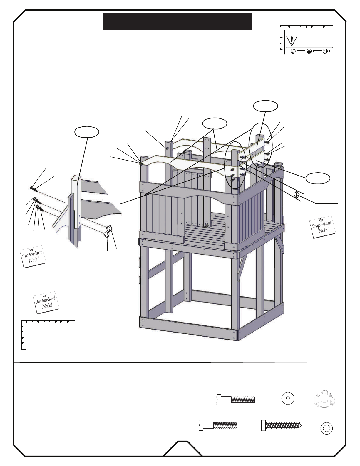
TOWER ASSEMBLY
:
11S TE P
* From the inside of the playhouse, place both WQ32 into its place so you can see the
correct orientation.
* Insert two T-Nuts "h" into both WQ32.
* Attach both WQ32 extensions into uprights (WQ06a & WQ06b) with bolt "e8".
* From the inside of the playhouse, insert the two remaining T-Nuts "h" as shown.
* Attach both WF18 with bolts"e6" and wood screws "b2" from the front and back of the playhouse.
* Attach WF19 with wood screws "b2".
* Attach WD20 with wood screws "b2" about 3" front the top.
WQ32
h
e6
k2
WF18
WD20
k2
m
e6
b2
k2
Note: It is vital that the fort
be level after this
phase!
k2
b2
b2
k2
WF19
e6
m
m
k2
k2
e8
Beware of the different bolts and screws
MAKE SURE FRAME IS
SQUARE BEFORE
PROCEEDING TO
NEXT PHASE!
3"
Note spacing
WQ06a
h
h
WQ06b
BACK
ITEMS NEEDED
(2) WF18 Top Double Arch Board 1×6×54
(1) WF19 Top Arch Board 1×6×31
(1) WD20 Top Brace 1×4×31
(2) WQ32 Upright-G 3×4×15 29/32
27
e8
e6
HARDWARE NEEDED
(4)
b2
(2)
k2
(8)
(14)
h
(6)
m
(6)
Page 30
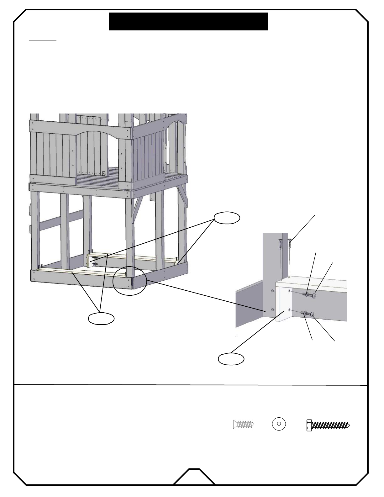
TOWER ASSEMBLY
:
12S TE P
* Attach four WF10 with wood screws "b2".
* Attach both WF11 with wood screws "a3".
WF11
WF10
WF10
k3
k2
a3
b2
b2
ITEMS NEEDED
(4) WF10 Sandbox Seat Support 1×6×4 1/2
(2) WF11 Sandbox Seat 1×6×47 1/4
28
a3
HARDWARE NEEDED
b2
(8)
k2
(8)
(8)
Page 31
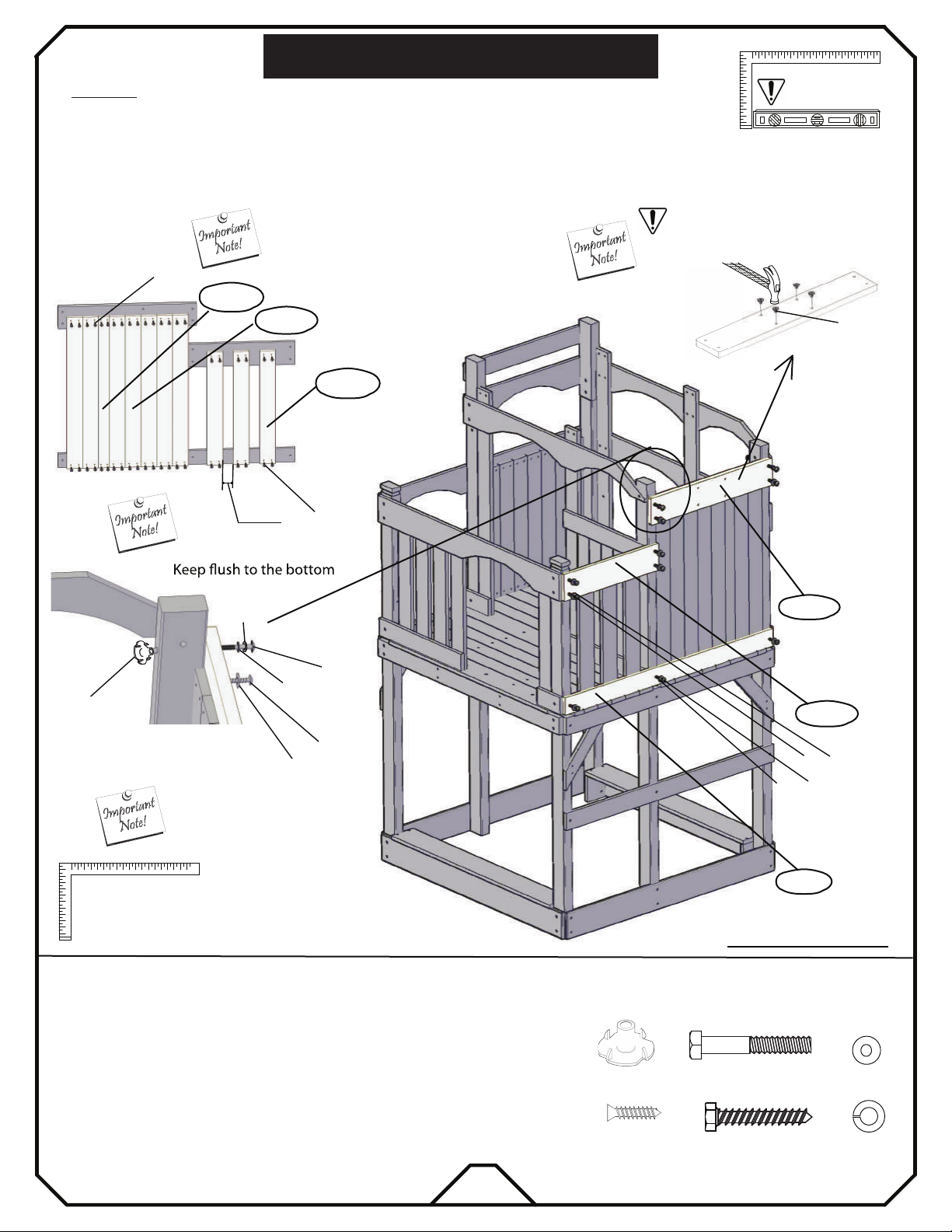
T O W E R A S S E M B L Y
TOWER ASSEMBLY
:
13 S T E P
* Insert four T-nuts "h" into the backside of WF29 for use in Step22.
* Attach WF29 with bolts "e5" and wood screws "b2".
* Attach WF27 and WD09 with wood screws "b2".
* From the inside of the playhouse, attach seven WC17b and one WC17a with wood screws "a3"
* From the inside of the playhouse, attach three WD24 with wood screws "a3".
This is a slightly smaller board
Insert(4)T-nuts into backside
of "WF29" for use in Step22
a3
WC17a
WC17b
WD24
Note: It is vital that the fort
be level after this
phase!
h
h
MAKE SURE FRAME IS
SQUARE BEFORE
PROCEEDING TO
NEXT PHASE!
2 3/8"
m
k2
k2
a3
b2
e3
WF29
WF27
b2
k2
b2
k2
WD09
Right wall assembly
ITEMS NEEDED
(1) WF27 Gazebo Guardrail 1×6×23 29/32
(1) WF29 Swing Attaced Board 5/4×6×31
(1) WD09 First Floor Guardrail 1×4×52 13/16
(3) WD24 Playhouse Wall Slat-A 1×4×27 9/16
(1) WC17a Wall Slat-A 1×3×37
(7) WC17b Wall Slat-B 1×4×37
29
HARDWARE NEEDED
h
(6)
a3
(44)
e3
b2
(2)
(9)
k2
(11)
m
(2)
Page 32
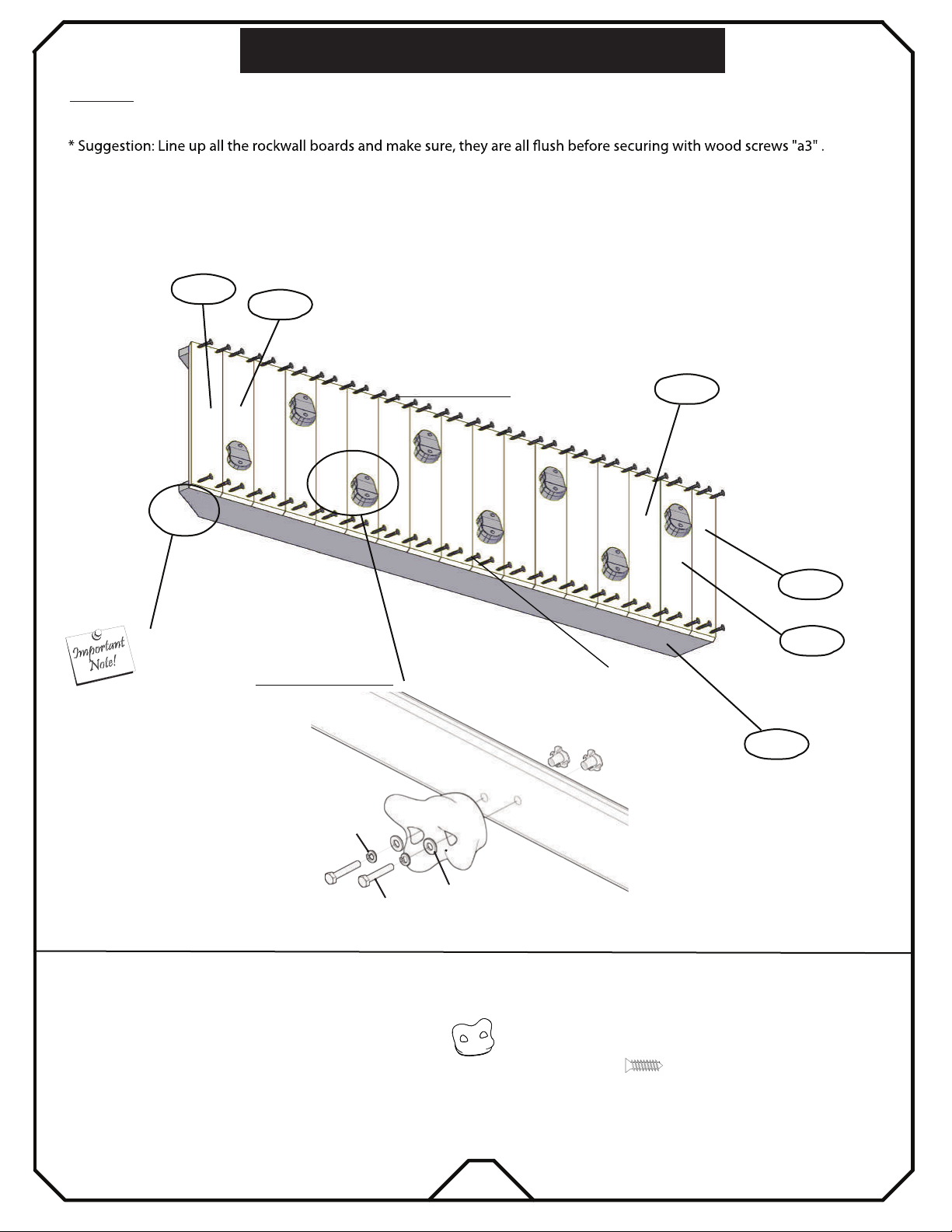
e
:
14S TE P
* Create the rockwall by attaching two WD38 with seventeen rockwall boards. Note the orientation of the holes.
* From the back of assembled rock wall insert T-Nuts.
* Install the climbing rocks ( See detail diagram below ).
ROCKWALL ASSEMBLY
WD39
WD40
Note orientation
Top of Rockwall
ROCK ATTACHMENT
1/4” Split
Washer
a3
T-Nuts
WD39
WC42
WD40
a3
WD38
ITEMS NEEDED
(2) WD38 Rockwall Rail 5/4×4×59 3/4
(8) WD39 Rockwall Board-A 1×4×21
(8) WD40 Rockwall Board-B 1×4×21
(1) WC42 Rockwall Board-C 1×3×21
1/4” Washer
1/4”-20 x 1-1/4
Hex Head Bolt
(2) CLIMBING ROCK 4-PACK
BP011-GYBR
w/ HARDWARE
30
HARDWARE NEEDED
a3
(68)
PLEASE REFER TO
ACCESSORY PLAN FOR
INSTALLATION INSTRUCTIONS
AND HARDWARE
Page 33
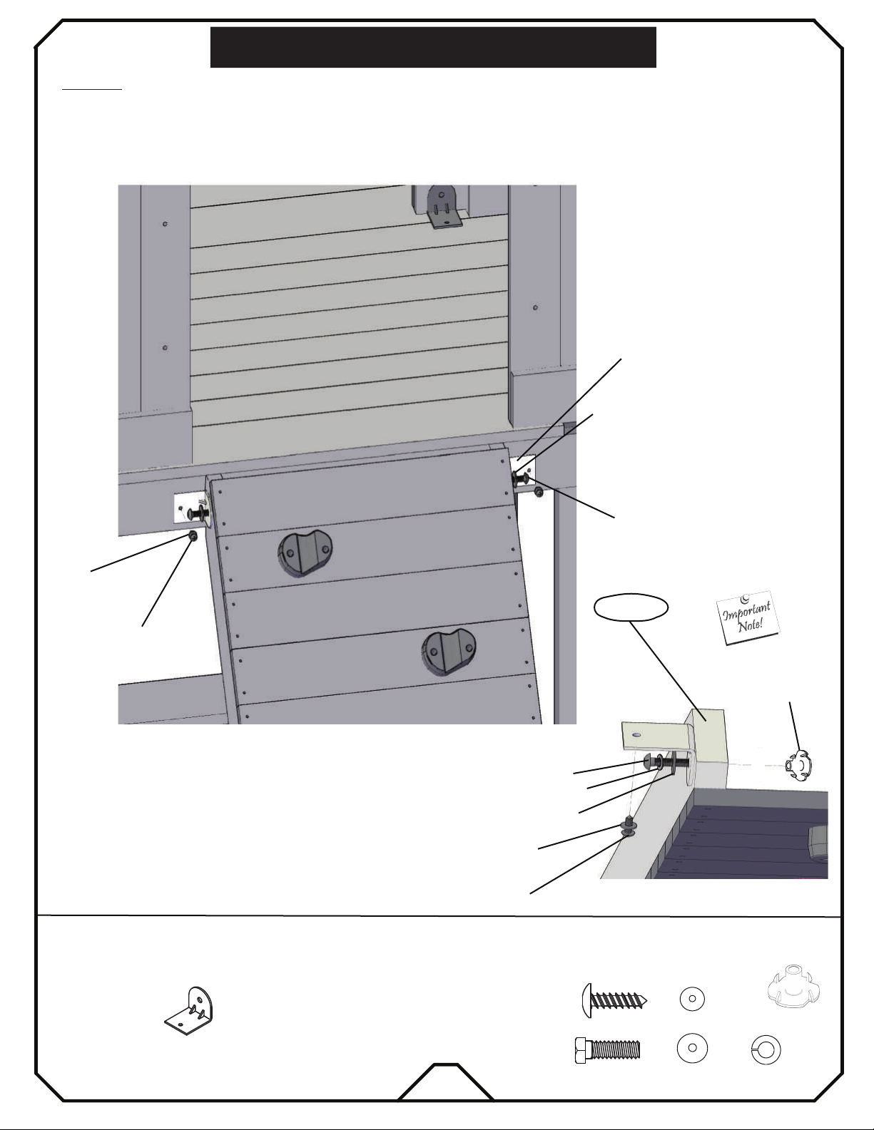
ROCKWALL ASSEMBLY
:
15STEP
* Attach both L brackets "M003" to Rockwall (See detailed diagram below).
* Attach Rockwall with installed L brackets "M003" to the playset's back wall.
M003
k4
WD03
k4
1” Truss Head Screw
1” Truss Head Screw
WD38
h
e9
m
k2
k4
1” Truss Head Screw
ITEMS NEEDED
(2) M003
31
HARDWARE NEEDED
1” Truss Head Screw
(2)
e9
(2)
k4
(2)
k2
(2)
h
(2)
m
(2)
Page 34
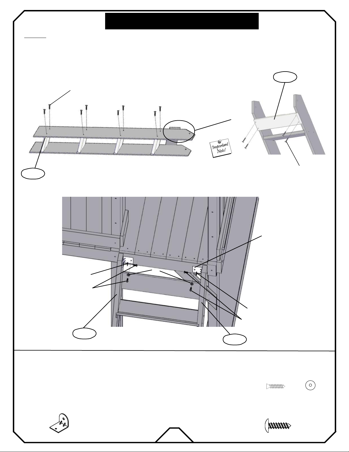
LADDER ASSEMBLY
:
16S TE P
* Create the ladder by attaching four WD36 in between WD34 and WD35. They should fit comfortably inside the notches
and securing with wood screws "a3".
* Attach WD37 to ladder with wood screws "a3".
* Attach ladder to the playset's left wall using both L bracket "M003" and 1” Truss Head Screws.
WD37
a3
WD34
WD35
WD36
1” Truss Head Screw
WD07
k4
Note orientation
a3
M003
k4
k4
1” Truss Head Screw
WD34
ITEMS NEEDED
(1) WD34 Ladder Rail(Left) 5/4×4×54 3/8
(1) WD35 Ladder Rail(Right) 5/4×4×54 3/8
(4) WD36 Ladder Step 1×6×23 29/32
(1) WD37 Ladder Block 1×4×20
(2) M003
32
WD35
HARDWARE NEEDED
a3
(20)
1” Truss Head Screw
(4)
k4
(4)
Page 35

ROOF ASSEMBLY
:
17 S T E P
* Create the short side of the roof by laying out one WF55 and four WF54 with two WD44 boards, securing with wood
screws "a3".
* Flip over assembly and attach WB52 with wood screws “a4”.
* Create the long side of the roof by laying out one WF55 and eight WF54 with two WD43 boards, securing with
wood screws "a3".
* Flip over assembly and attach WB53 with wood screws “a4”.
* Create a peak using both the short and long roofs, and attach WH51 under the roof of the assembly, securing with
wood screws "a3" underneath, sides and on top, as shown.
a3
WF54
WD44
top side of short roof
a3
a3
WF55
WF55
WF54
a3
WD44
17 1/2"
3"
a4
WB52
under side of short roof
Note orientation of WF55
* Make sure all slats are flush
before securing with wood screws.
31 1/8''
WH51
a3
under side of roof
17 1/2"
a4
3"
a3
WD43
WD43
top side of long roof
under side of long roof
ITEMS NEEDED
(2) WD43 Sunburst Frame-A 1×4×45
(2) WD44 Sunburst Frame-B 1×4×25
(1) WH51 Roof Beam-A 2×2×31
(1) WB52 Roof Beam-B 1×2×19 7/8
(1) WB53 Roof Beam-C 1×2×40 15/16
(12) WF54 Roof Board-A 1×6×36 5/16
(2) WF55 Roof Board-B 1×6×36 5/16
WB53
33
top side of roof
HARDWARE NEEDED
a3
(66)
a4
(14)
Page 36
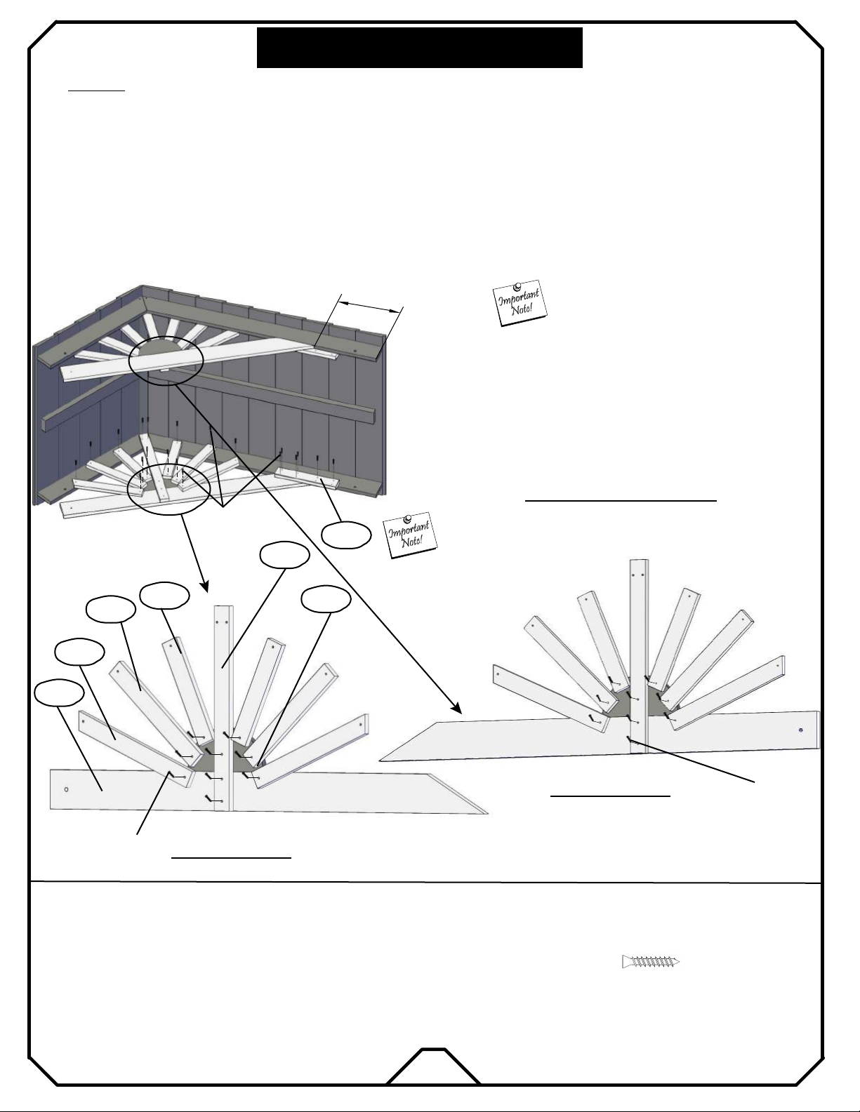
ROOF ASSEMBLY
:
18 S T E P
* Create one sunburst for the front and one for the back, with wood screws "a4" (See diagrams below).
* Secure both sunburts to the roof from the inside with wood screws "a4".
* From the inside, secure one WC46 to longe side of each sunburst with wood screws "a4".
11 11/16''
* Sunbursts should be mirror images!
* Rays of sunburts should be spread out evenly.
WC60
WD45
WC50
a4
a4
WC49
Back Sunburst
WC48
WC46
WD47
Interior views of sunburst
* Use only 6 "a4" wood screws.
Front Sunburst
a4
ITEMS NEEDED
(2) WD45 Sunburst Frame-C 1×4×45 7/16
(2) WC46 Roof Brace Fixed 1×3×11 7/16
(2) WD47 Sunburst DecoBoard 1×4×4 7/8
(2) WC48 Sunburst Trim-A 1×2×18 10/32
(4) WC49 Sunburst Trim-B 1×3×9 27/32
(4) WC50 Sunburst Trim-C 1×3×11 13/16
(4) WC60 Sunburst Trim-D 1×3×13
HARDWARE NEEDED
a4
(46)
34
Page 37
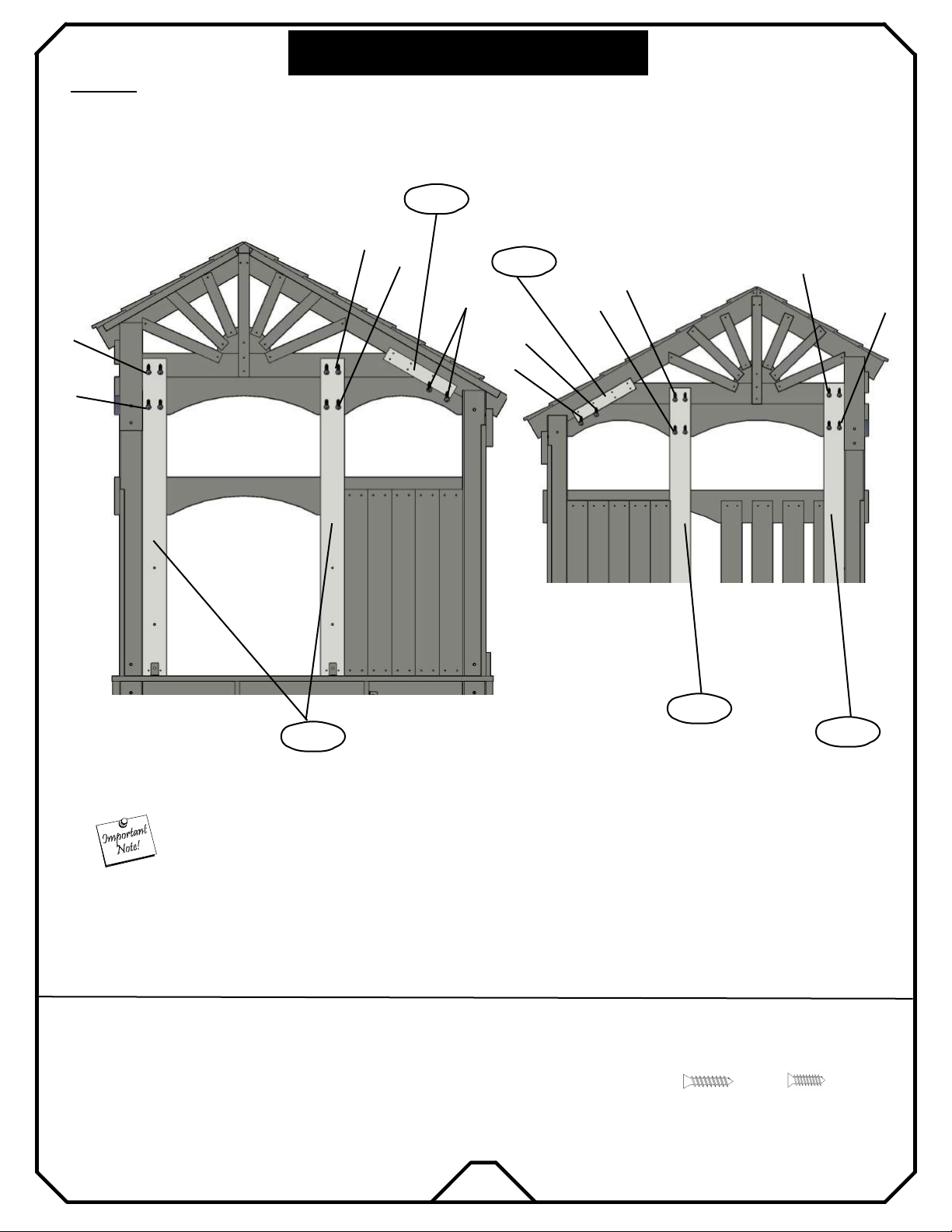
ROOF ASSEMBLY
:
19 S T E P
* Mount the roof to the playhouse.
* Secure WD25a, WD26b and WD25c with wood screws "a3".
* Secure WC46 with wood screws "a4".
WC46
a3
a3
a3
a3
a4
WC46
a4
a4
a3
a3
a3
a3
WD25b
Inside view of back
The shorter roof side gets mounted to the taller post.
The longer roof side gets mounted to the shorter post.
WD25a
WD25c
Inside view of front
HARDWARE NEEDED
a3
(16)
a4
(4)
35
Page 38
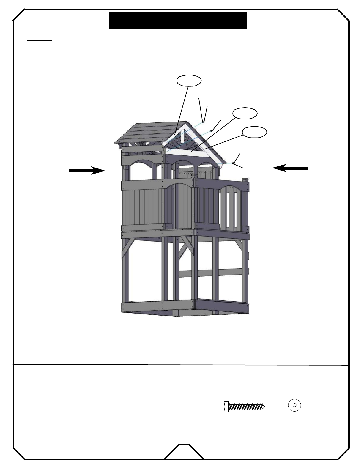
ROOF ASSEMBLY
:
20S TE P
* Secure the roof with wood screw "b2", three time in the front and three times in the back.
NOTE: To prevent wood splitting, pre-drill all locations where “b2” screws are used.
WD44
k2
b2
WD45
b2
WD43
b2
k2
Back
Front
36
Front
b2
HARDWARE NEEDED
k2
(6)
(6)
Page 39
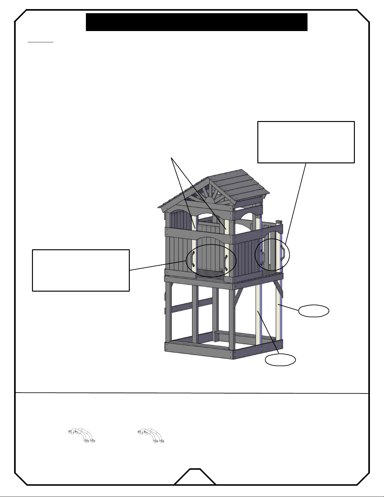
SAFETY HANDLE ATTACHMENT
:
21S TE P
* Attach side wall’s safety handle with BP 007 (wood screws) accessory plan.
* Attach front wall’s safety handle with BP 007T (T-nuts) accessory plan.
WD25b
PLEASE REFER TO ACCESSORY
PLAN BP 007 (Wood Screws) FOR
INSTALLATION INSTRUCTIONS
AND HARDWARE.
PLEASE REFER TO ACCESSORY
PLAN BP 007T (T-Nuts) FOR
INSTALLATION INSTRUCTIONS
AND HARDWARE.
ITEMS NEEDED
(2 PAIR) SAFETY HANDLE
WQ02b
WQ06b
BP 007T-Y
w/ T-Nuts
BP 007-Y
w/ Wood Screws
37
Page 40
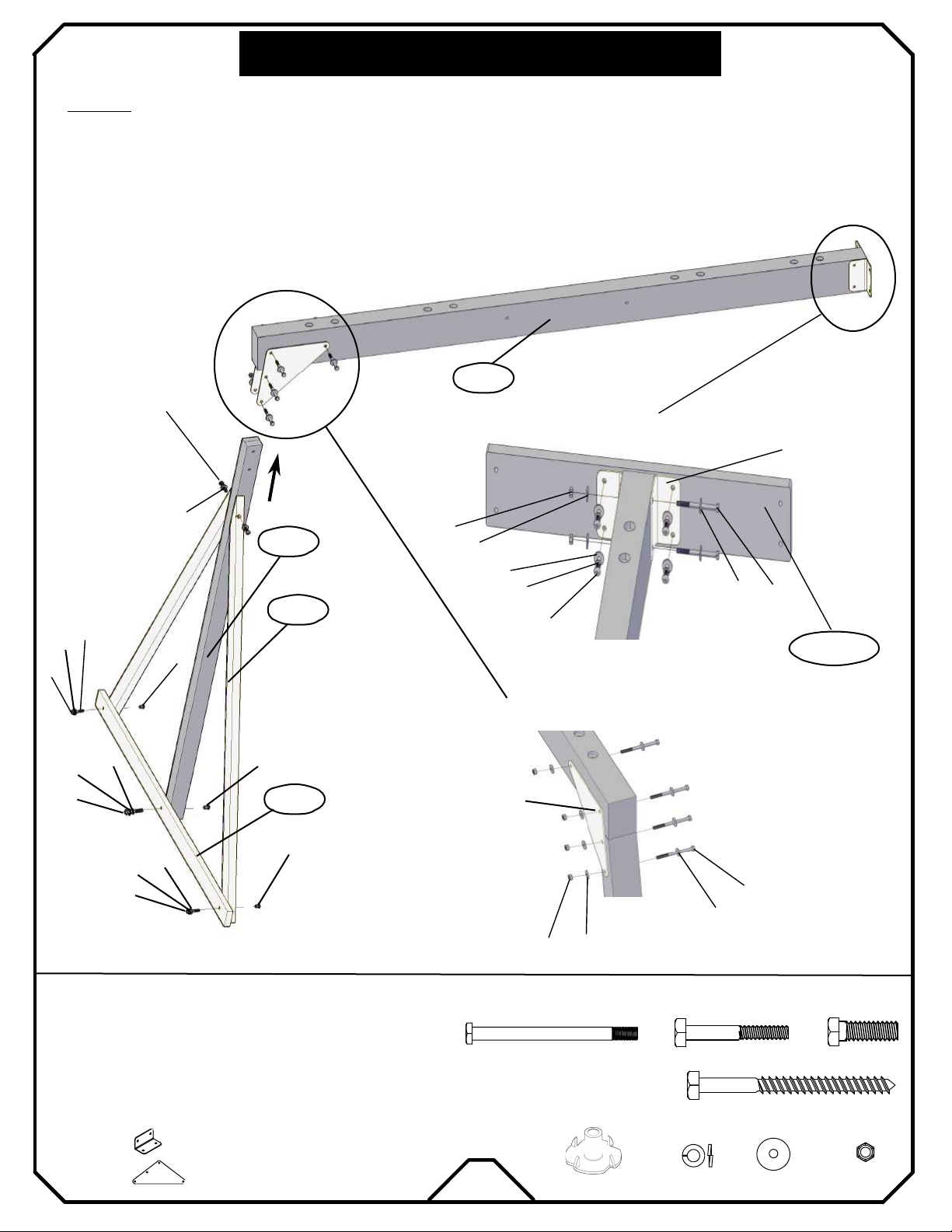
SWING BEAM ASSEMBLY
:
22S TE P
* Prepare swing beam WZ59 by mounting two triangle plates "M100" and two angle brackets "M005" with bolts "f3".
* Insert T-Nuts "h" into both WQ56 and WU58.
* Create swing beam leg with both WQ56, WQ57 and WU58 with bolts "e4", "e7" and wood screws "b1".
* Attach the swing beam WZ59 to the prepared swing beam leg.
* Attach the completed swing beam to the playset's right wall with bolts "e9".
LA251
b1
M005
e6
m
f3
m
k2
k2
e6
m
k2
k2
LD254
k2
k2
g
k2
LG252
m
f3
e9
h
WF29
f3
h
LG253
M100
f3
f3
h
f3
k2
g
k2
ITEMS NEEDED
(1) LA251 swing beam 4x6x89 1/2
(2) LG252 swing beam leg-A 2x4x82 1/2
(1) LD254 swing beam leg-B 3x4x83
(1) LG253 swing beam ground support 2x4x89
(2) M005
(2) M100
f3
38
HARDWARE NEEDED
e6
(7)
b1
h
(3)
m
(7)
(2)
k2
(21)
e9
(4)
(2)
g
(6)
Page 41
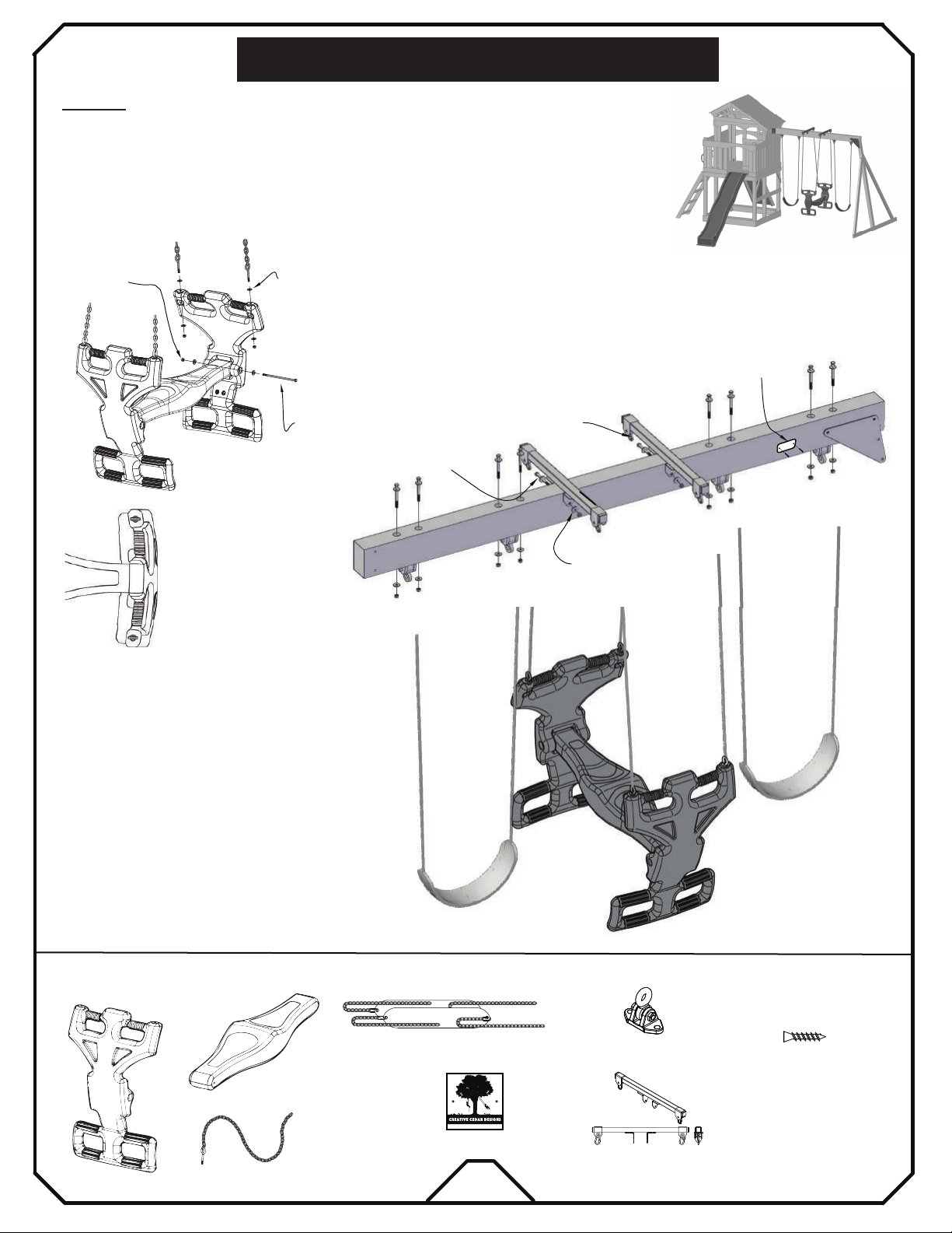
SWING BEAM ASSEMBLY
:
23S TE P
* Install swing hangers in accordance with your accessory instructions.
* Install both glider supports "BP 020" as shown.
* Build two person glider ( See diagram ).
* Hang the completed glider to glider suport and fasten.
* Hang both swings to the swing hangers and fasten.
1/2” LOCK NUT
& 3/4” WASHERS
EYE BOLT
ORIENTATION
1/2” LOCK NUT
& 7/8” WASHERS
NOTE:
TIGHTEN LOCK NUTS
UNTIL (3) THREADS
ARE EXPOSED
7-1/2” HEX BOLT
& 3/4” WASHER
& FENDER WASHER
PLEASE REFER TO
ULTIMATE SWING HANGER
INSTALLATION INSTRUCTIONS.
TIGHTEN QUICK LINK
AFTER ATTACHING CHAIN
4" HEX BOLT
1/2” LOCK NUT
& 7/8” WASHERS
NOTE:
FENDER WASHER
TIGHTEN LOCK NUTS
& LOCK NUT
UNTIL (3) THREADS
ARE EXPOSED
7-1/2” HEX BOLT
& 3/4” WASHER
CENTER ID TAG AND
ATTACH WITH
3/4” DECK SCREWS
EYE BOLT
ORIENTATION
(1) GLIDER - BP 018-GY
(2) GLIDER ARM
w/ HARDWARE
(4) CHAIN w/ EYE BOLT
ITEMS NEEDED
(1) GLIDER SEAT
(2) ULTIMATE SWING SEAT - BP014-Y
(1) ID Tag
CreativeCedarDesigns.com
39
HARDWARE NEEDED
(2) 3/4 Deck Screw
(4) ULTIMATE SWING HANGER
KC 003 w/ HARDWARE
(1 PAIR) GLIDER BRACKET
BP 020
w/ HARDWARE
Page 42
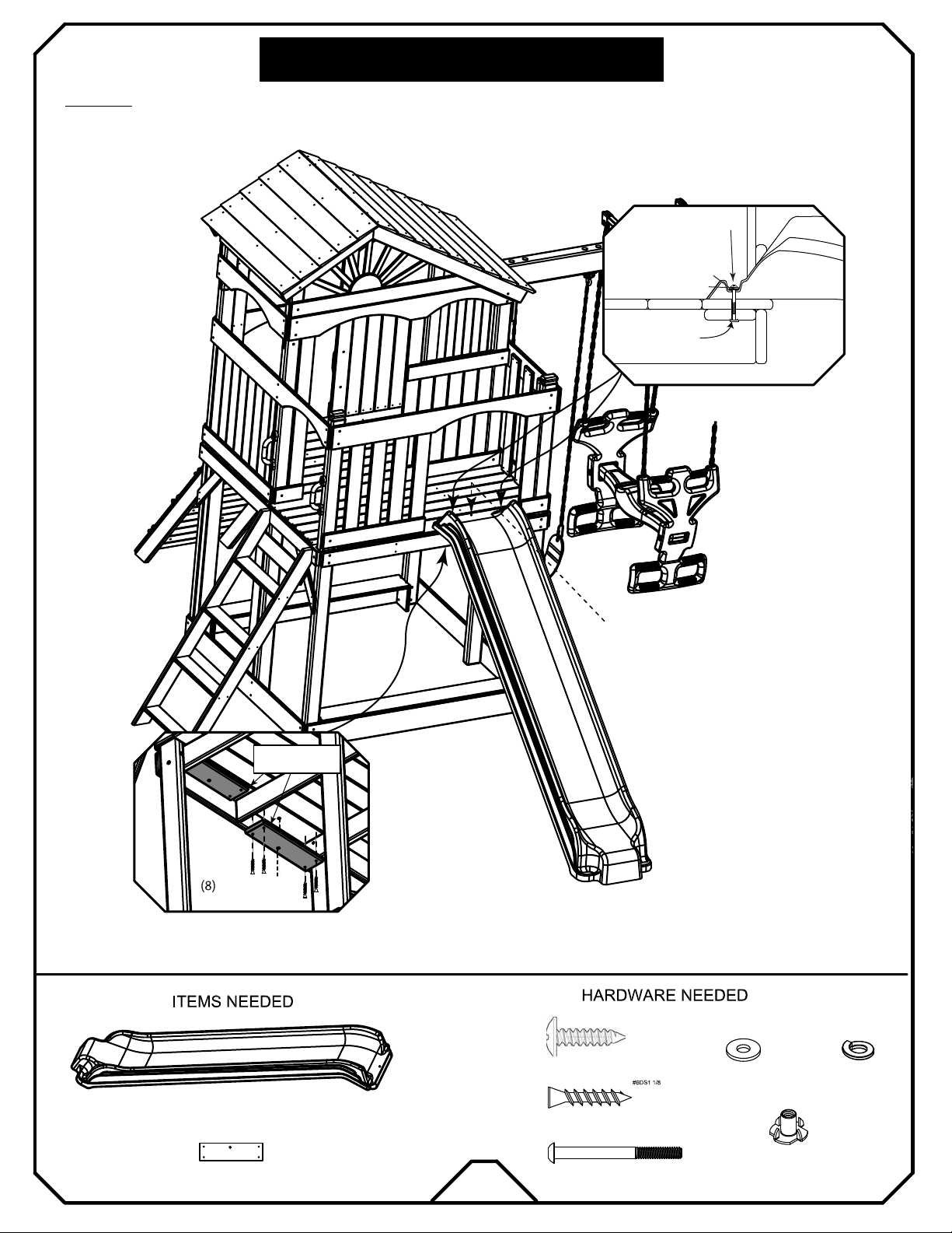
SLIDE ATTACHMENT
:
24S TE P
ALIGN SLIDE WITH PRE-DRILLED HOLES ON DECK.
INSTALL (1) 1" TRUSS HEAD SCREW IN THE
CENTER HOLE PER SLIDE.
1/4" x 2" Button
Head Bolts
1/4" Lock Washer
1/4" Flat Washer
1/4" T-NUT
SIDE VIEW
SLIDE SUPPORT
BOARD
1 1/8" Deck
Screws
ALIGN HOLE IN SUPPORT BOARD
WITH HOLE IN UNDERSIDE OF DECK BOARD
(1) 8’ SLIDE
(2) WD116 - SLIDE SUPPORT BOARD - 11/16 " X 3 1/2" X 12"
40
(1) 1" Truss
Head Screws
(1)
1" Truss Head Screws
(8)
1 1/8" Deck Screws
(2)
1/4" x 2" Button Head Bolts
(2)
1/4" Flat Washer
(2)
1/4" T-Nut
(2)
1/4" Lock Washer
Page 43

ANCHORING
:
25 S T E P
* Place six stakes in to the ground next to the playset as shown.
* Secure the stakes with hardware shown ( See diagram ).
Note: Failure to use stakes can void warranty & cause injury.
Final Step: Double check and make sure every bolt, screw
and nut is tight. Make sure every board is secure. Make sure
the fort is level and enjoy your playset.
e
METAL STRAP
FLAT WASHER
1-1/2’’ LAG BOLT
STAKE
STAKE
STAKE
STAKE
ANCHOR
ITEMS NEEDED
(2) ANCHOR 4-PACK w/ HDW
BP001-B
STAKE
41
STAKE
HARDWARE NEEDED
(8) 1-1/2’’ LAG BOLT
(8) FLAT WASHER
Page 44
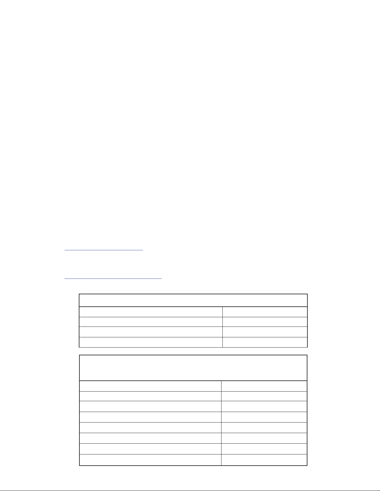
LIMITED WARRANTY
Creative Cedar Design (CCD) offers many fun, interactive, and safe play sets. We only guarantee the
original purchaser that this product is free of defects for 30 days from the date of purchase. The
product registration card, along with a dated purchase receipt, must be returned to CCD within 30 days.
Within a 30 day period, CCD will repair or replace, at our option, defective merchandise free of charge,
provided that the defective part is a manufacturer’s defect and not seasonal check. CCD requires
photographs of the part in question. The customer service center must be contacted for authorization
for all warranty related s
and handling charges, even if the warranty claim has been approved. Depending on the size of the part,
quantity of the order, availability of part at the time, the claim can take between 1-3 weeks.
Under this warranty there will be a replacement for the defective component of the play set. A 1-year
Warranty is available on all components with a manufacturer’s defect. A 10-year Limited Warranty is
available on wood parts (4x6 and 4x4) against wood rotting and termite damage. This guara
effective only if the product is used for the purpose for which it was designed, maintained with
accordance to the instructions, and installed at a residential, single family dwelling.
The warranty does not cover, (a) products which have been damaged by acts of God, negligence,
misuse, or accident, or which have been modified or repaired by unauthorized persons; (b) the cost of
labor; (c) the cost of shipping the product, any part, or any replacement product or part; (d) damage
caused by the addition of any accessories not sold by CCD.
Cosmetic defects that do not affect the structural integrity of the product, or natural defects of wood
as warping, checking or any other physical properties of wood that do not present a safety hazard,
such
are not covered by this warranty. Defects that develop because the product is exposed to extreme
climate conditions are not covered by this warranty. Defects that develop as a result of faulty or
improper installation of the product are also not covered by this warranty.
For warranty service or replacement part information, please visit our website at
www.creativecedardesigns.com and submit a request. If you have any additional questions, please call
1-888-363-4967.
Replacement parts are available for purchase after the warranty expires. Please contact us by email at
[email protected] for details.
ervice. After the 30 day period, the customer is responsible for all shipping
ntee is
Warranty: 1 Year for all Components
Days from Date of Purchase Cost to Customer
With in 30 days No Cost
After 30 days , but within 1 year Shipping and Handling (S&H)
Warranty: 10 Year Pro Rated for Wood Parts
(4x4 and 4x6 ONLY against wood rot and termite damage)
Years from Date of Purchase Cost to Customer
0-1 (after first 30 days through Year 1) Cost of S&H and 0% on part
2-3 Cost of S&H and 20% on part
4-5 Cost of S&H and 40% on part
6-7 Cost of S&H and 60% on part
8-9 Cost of S&H and 80% on part
Over 10 Cost of S&H and 100% on part
42
Page 45

Warranty claim procedure
If you are confident that your play system has been installed and maintained
properly, and you have a warranty claim, proceed with the following steps:
1. We will need copy of your proof of purchase (Vendor sales receipt only.)
2. We require a brief written description of the warranty issue.
3. Photos of warranted parts and of the entire play system.
If any of the above steps are not completed, there may be delays in the
completion of your claim, or possibly warranty cancellation.
Mail information to:
Creative Cedar Designs
PO Box 4901
Chattanooga, TN 37405
Or email at
Our customer service department will review the claim and make contact
with the customer by mail or by phone.
1-888-363-4967
Page 46

PRODUCT REGISTRATION CARD
Please complete this Product Registration Card along with a copy of the receipt and return to Creative
Cedar Designs, within 30 days of original purchase in order to validate time of purchase for warranty.
Or register at www.creativecedardesigns.com
Name:________________________________________________________________
Address: _______________________________________________________________
City, State, Zip Code: ___________________________________________________
Phone:________________________________________________________________
Email Address: __________________________________________________________
Date of Purchase: _______________________________________________________
Purchased Through:__________________________________________________
City, State, Zip Code: ___________________________________________________
Playset Name: ____________________________ Playset Model: ________________
Page 47

PRODUCT REGISTRATION CARD
Please complete this Product Registration Card along with a copy of the receipt and return to Creative
Cedar Designs, within 30 days of original purchase in order to validate time of purchase for warranty.
FOLD HERE
Creative Cedar Designs
PO Box 4901
Chattanooga, TN 37405
Place
Stamp
Here
 Loading...