

XBoard mini.book Page 3 Thursday, April 21, 2005 11:09 AM
Owner’s Manual
© 2005 E-MU Systems
All Rights Reserved
PN: 02EM770006000
Revision: A
E-MU World Headquarters
E-MU Systems
1500 Green Hills Road
Scotts Valley, CA
95067-0015
USA
Europe, Africa,
Middle East Creative Labs
Ballycoolin Business Park
Blanchardstown
Dublin 15
IRELAND
E-MU Japan
Creative Media K K
Kanda Eight Bldg., 3F
4-6-7 Soto-Kanda
Chiyoda-ku, Tokyo
101-0021
JAPAN
www.japan.creative.com
X Board 3
XBoard mini.book Page 4 Thursday, April 21, 2005 11:09 AM
Important!
The complete X Board manual is available in .pdf format on the included CD-ROM.
Important
Le manual français de l’ X Board est disponible au format .pdf, sur la CD-ROM
inclus.
Wichtig
Das deutsche Handbuch ist als .pdf Dokument vom enthaltenen CD-ROM
vorhanden.
E-MU Systems 4

XBoard mini.book Page 5 Thursday, April 21, 2005 11:09 AM
Table of Contents
Introduction .................................................................7
Requirements .......................................................................................................8
On a PC: ................................................................................................................... 8
On a Mac: ................................................................................................................. 8
Package Contents ................................................................................................. 8
Optional ................................................................................................................... 8
Hardware Installation ..........................................................................................8
Connecting the X Board to your Computer ........................................................ 9
USB Connection ...................................................................................................... 9
MIDI Connection ....................................................................................................9
MIDI Interface ........................................................................................................ 10
Software Installation .........................................................................................10
Macintosh OS X .....................................................................................................10
Windows 2000 ....................................................................................................... 10
Windows XP ........................................................................................................... 11
Uninstalling all Audio Drivers and Applications ................................................11
Troubleshooting ................................................................................................12
Main Panel Controls ....................................................16
Back Panel Description ...............................................19
Powering the X Board .................................................20
Inserting Batteries into the X-Board ......................................................................20
Basic Operations .........................................................21
Entering Data .....................................................................................................21
Selecting Patches ................................................................................................21
Storing Patches ..................................................................................................22
X Board 5
XBoard mini.book Page 6 Thursday, April 21, 2005 11:09 AM
Changing the MIDI Channel .............................................................................22
Transposing the Keyboard .................................................................................22
Editing Patches ..................................................................................................23
Scrolling Text Display ............................................................................................23
16 Channel Control Mode .................................................................................24
Note Latch Mode ................................................................................................25
Snap Shot ...........................................................................................................26
Bypass Mode ......................................................................................................26
Edit Parameters ..................................................................................................27
Semitone Transpose ...............................................................................................27
Velocity Curve Select ..............................................................................................27
16 Channel CC Number .......................................................................................27
Latch High/Low Note ............................................................................................28
Save CC Value in Patch ..........................................................................................28
CC Send On Recall ................................................................................................28
PGM Send on Recall ..............................................................................................28
Bank Send MSB ......................................................................................................28
Bank Send LSB .......................................................................................................28
Send Prog Change ..................................................................................................29
Aftertouch On/Off .................................................................................................29
Program Change (PGM) Browse Mode ................................................................29
X1 Functions ..........................................................................................................30
Index ......................................................................... 31
E-MU Systems 6
XBoard mini.book Page 7 Thursday, April 21, 2005 11:09 AM
Introduction
INTR
ODUCTION
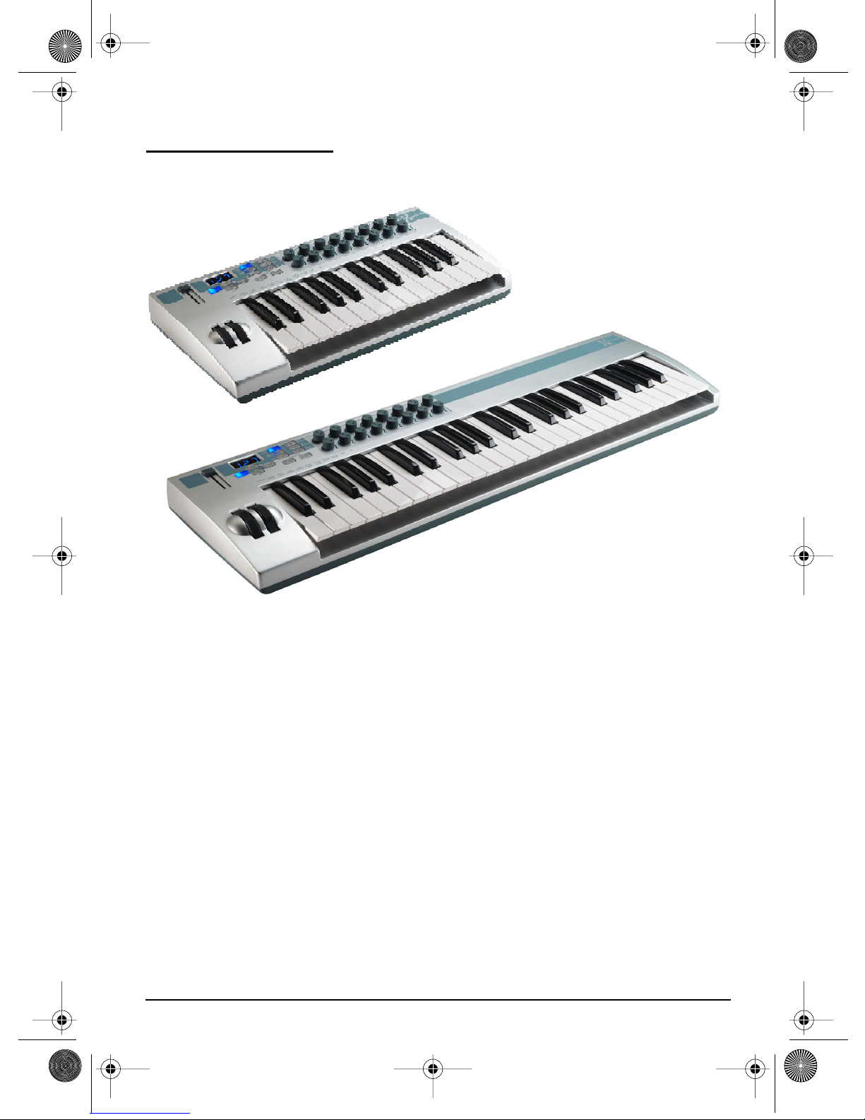
Congratulations on your purchase of the E-MU X Board 25 or X Board 49 USB/
MIDI controller. The X Board professional USB/MIDI controllers offer unmatched
playability, real-time control and programmability in portable 25 key or 49 key
packages. Both models feature full-size velocity-sensitive keys with aftertouch, pitch
and modulation wheels and 16 controller knobs. These keyboards are ideal for
either studio or stage use since they can be used as stand-alone MIDI controllers or
with a USB equipped PC or Macintosh computer. The X board MIDI output can
even be used as a MIDI interface for your computer when connected via USB. The X
Boards are ultra-portable and can be powered via USB, battery, or using the
optional 6 VDC power supply.
Each of the 16 controller knobs can be programmed to any controller number on
any MIDI channel. The keyboard can be transposed up or down ±4 octaves in order
to play in any key and any pitch.
Both X Boards contain a host of extra features. The “Snap Shot” feature lets you
send multiple program changes and controller values with a single button press.
The “XBoard Latch Mode” lets you define a section of the keyboard as On/Off
triggers—perfect for drum loops. Each of the 16 internal patches has a programmable footpedal/footswitch setting, can select one of eight velocity curves, and can
send program changes for up to 16 MIDI channels.
X Board 7

XBoard mini.book Page 8 Thursday, April 21, 2005 11:09 AM
Introduction
Requirements
The included X Board Control software provides an intuitive desktop interface that
makes it easy to create custom templates for all your favorite hardware and software
instruments.
On a PC:
You must be running Windows 2000 or XP, and your computer must support USB
to communicate with the X Board. The X Board can operate in MIDI Output mode
without a computer if 6VDC power is supplied via a DC adapter or batteries.
On a Mac:
You must be running Mac OS X to connect the X Board. The X Board can operate in
MIDI Output mode without a computer if 6VDC power is supplied via a DC
adapter or batteries.
Package Contents
•X Board Keyboard
• USB Cable
• CD-ROM containing the following software bundle
+ X Board USB Drivers
+ X Board Control software
+ Proteus X LE Desktop Sound Module
+ Ableton Live Lite 4 for E-MU
+ Adobe PDF Reader
+ PDF manual for X Board and X Board Control software
• This Owner’s Manual
Optional
• DC Power Adapter (contact E-MU Systems)
Hardware Installation
The connection diagrams on the following pages show how to connect the X Board
to your computer or to another MIDI device.
The supplied USB cable provides power and a two-way data link between the X
Board and your computer. The USB port on your computer is a small (1/8” x 3/8”)
rectangular opening. The connector is keyed so you cannot plug it in wrong. The
other end of the USB cable is square and plugs into the back of the X Board. This
end is also keyed to prevent incorrect insertion.
If the X Board is not connected to the computer via USB it requires a source of
power in the form of a 6VDC adapter (tip positive) or (3) AA batteries.
E-MU Systems 8
XBoard mini.book Page 9 Thursday, April 21, 2005 11:09 AM
Introduction
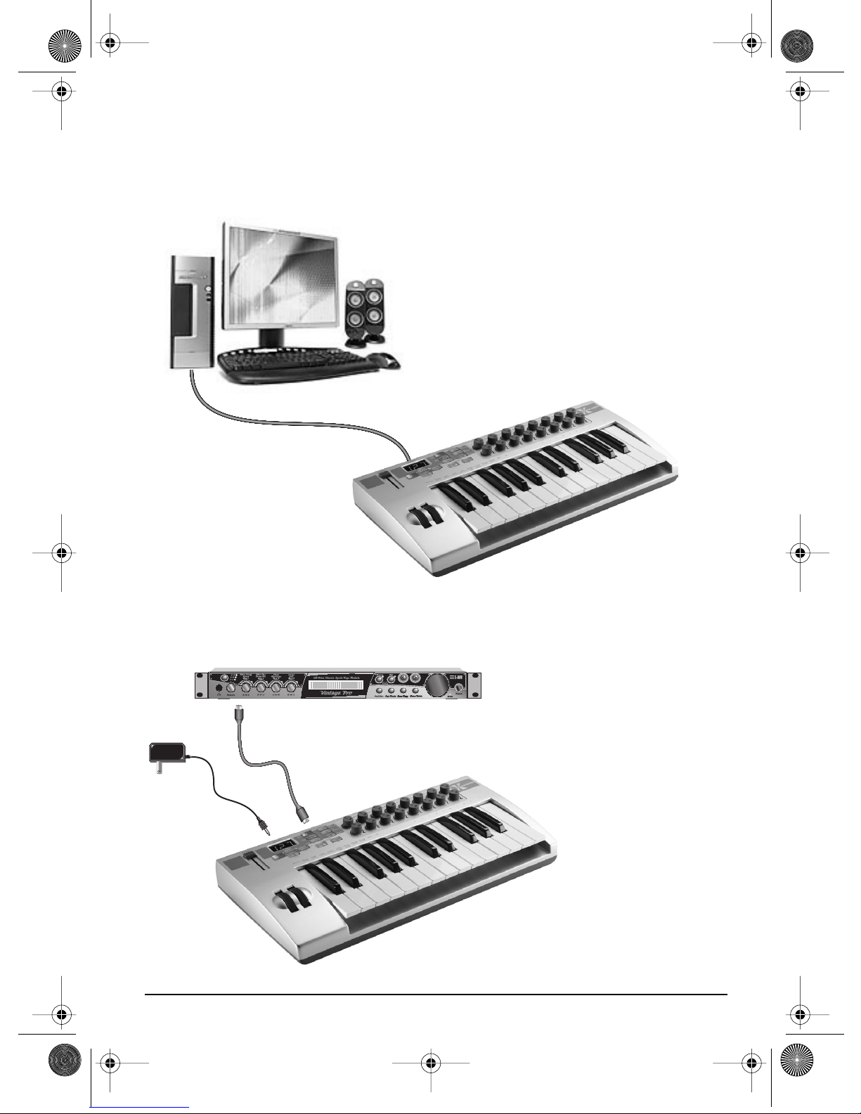
Connecting the X Board to your Computer
USB Connection
USB provides a two-way data link
between the X Board and your
computer and also supplies
power to the X Board. Always
connect to the USB port on the
computer itself—the USB port on
your computer keyboard will not
supply sufficient power.
U
S
B
C
a
b
l
e
MIDI Connection
MIDI Sound Module
CO1 A V 12 7 P PA:01RNIVTG
3
022
trn:Mellotron tr S
In
MIDI
Cable
6 VDC
Adapter
Out
X Board 9
The X Board sends MIDI
performance data to another
MIDI device, such as a MIDI
sound module. The X Board
always transmits MIDI data
except when “Thru” mode is
enabled.
(See page 30.)
XBoard mini.book Page 10 Thursday, April 21, 2005 11:09 AM
Introduction
U
S
B
C
a
b
l
e
Out
MIDI Sound Module
In
MIDI
Cable
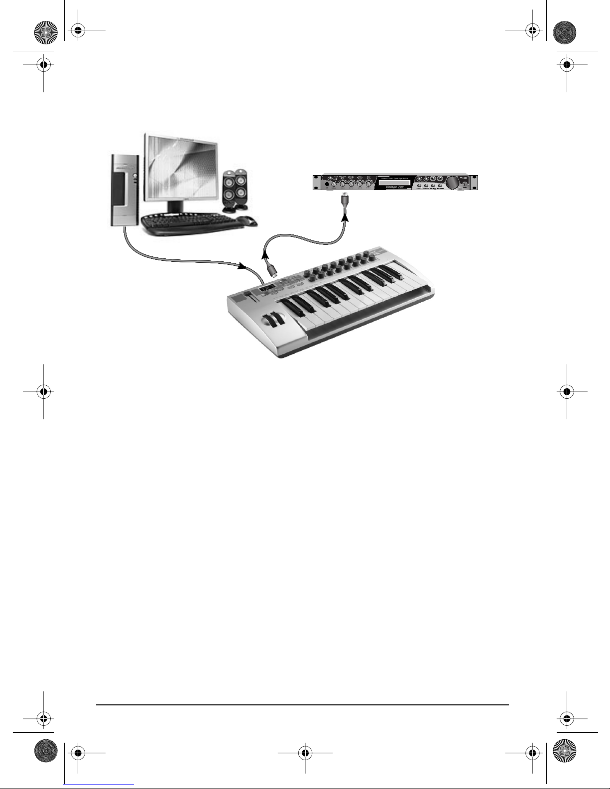
MIDI Interface
CO1A V12 7 P PA:01RNIVTG
3
trn:Mellotron tr S
022
The X Board can function as a MIDI interface when connected to your computer via
USB. Set the X Board MIDI port to “Thru”
(page 30)
to transmit MIDI from your
sequencing application to an external MIDI device.
Software Installation
Macintosh OS X
Follow these instructions to install the X Board USB drivers and editor/librarian
software on a Macintosh computer.
1. Double-click on the installer package.
2. Click on the lock icon and enter the administrator password you chose when
you installed OS X.
3. Follow the prompts to install the software.
Windows 2000
Follow these instructions to install the X Board USB drivers and editor/librarian
software on a Windows 2000 computer.
1. Make sure the X-Board is NOT CONNECTED to your computer.
2. Insert the E-MU software Installation CD into your CD-ROM drive. If Windows
AutoPlay mode is enabled for your CD-ROM drive, the CD starts running automatically. If not, from your Windows desktop, click
d:\setup.exe
also simply open the CD and double-click
(replace
d:\
with the drive letter of your CD-ROM drive). You can
Setup.exe
Start->Run
.
and type
E-MU Systems 10

XBoard mini.book Page 11 Thursday, April 21, 2005 11:09 AM
Introduction
3. The installation splash screen appears. Follow the instructions on the screen to
complete the installation. You will have the option to install:
•
E-MU X Board
•
Proteus X LE
•
Ableton Live Lite for E-MU
- USB Drivers and X Board Control Application
- A virtual sampling musical instrument (VSTi)
- A loop-based composition/improvisation tool.
•Adobe Acrobat Reader
4. Choose “Continue Anyway” when you encounter the “Windows Logo Testing”
warning screen. See the note on the following page.
5. When prompted, restart your computer.
6. Connect the X Board to your computer using the supplied USB cable.
Windows XP
Follow these instructions to install the X Board USB drivers and editor/librarian
software on a Windows XP computer.
1. First connect the X Board to your computer using the supplied USB cable. This
will allow Windows to install a USB Audio Device driver for the product. Wait
for this installation to complete.
2. Insert the E-MU software Installation CD into your CD-ROM drive. If Windows
AutoPlay mode is enabled for your CD-ROM drive, the CD starts running automatically. If not, from your Windows desktop, click
d:\setup.exe
also simply open the CD and double-click
(replace
d:\
with the drive letter of your CD-ROM drive). You can
Setup.exe
Start->Run
.
and type
3. The installation splash screen appears. Follow the instructions on the screen to
complete the installation. You will have the option to install:
•
E-MU X Board
•
Proteus X LE
•
Ableton Live Lite for E-MU
tool
(Windows only version at this time)
- USB Drivers and X Board Control Application
- A virtual sampling musical instrument (VSTi)
- A loop-based composition and improvisation
•Adobe Acrobat Reader
4. Choose “Continue Anyway” when you encounter the “Windows Logo Testing”
warning screen. See the note on the following page.
5. When prompted, restart your computer.
Uninstalling all Audio Drivers and Applications
At times you may need to uninstall or reinstall some or all of the X Board's applications and device drivers to correct problems, change configurations, or upgrade
outdated drivers or applications. Before you begin, close all X Board
applications. Applications running during the uninstallation will not be removed.
X Board 11

XBoard mini.book Page 12 Thursday, April 21, 2005 11:09 AM
Introduction
1. Click
2. Double-click the
3. Click the
4. Select the
5. In the
6. Click the
Start
->
Settings
->
Add/Remove Programs
Install/Uninstall
E-MU X Board
InstallShield Wizard
Yes
button.
Control Panel
.
icon.
tab (or
Change or Remove Programs
entry and then click the
dialog box, select the
button).
Change/Remove
Remove ALL
option.
button.
7. Restart your computer when prompted.
8. You may now re-install existing or updated E-MU device drivers or applications.
Note About Windows Logo Testing
When you install the X Board USB drivers, you will see a dialog box that informs
you that the driver has not passed Windows Logo testing.
However, the X Board USB drivers have been rigorously tested using the same test
procedures that a signed driver requires, and it passes in all important categories,
including those that measure the relative stability of the driver. So, it is perfectly
safe to install these drivers on your computer.
Troubleshooting
Lost Communication
Should you loose MIDI communication between your X Board and an audio application (Cubase, Sonar, etc) or the X Board Editor, the X Board drivers may need to
be re-selected in your application.
1. Go to your application's MIDI I/O settings, de-select the X Board for both
MIDI input and output (or select a different MIDI device).
2. Apply these changes and exit the dialog.
3. Re-enter the application's MIDI settings and re-select the X Board drivers. If this
does not work, the application may need to be restarted.
Wrong Driver in Windows XP or Windows 2000
You may encounter a situation where the X Board Control Editor or Proteus X LE
programs are not running properly, even though the MIDI device itself seems to be
working fine.
If this is the case, you may be in a situation where the Microsoft USB MIDI driver is
running, rather than the E-MU USB MIDI Driver. This may happen if you add a
USB Hub, or if you plug the X Board keyboard into a different USB port than the
one it was plugged into when you installed the X Board software.
E-MU Systems 12

XBoard mini.book Page 13 Thursday, April 21, 2005 11:09 AM
Introduction
To confirm the problem, do the following:
1. Temporarily disconnect any USB audio devices you may have connected (USB
audio/USB MIDI interfaces, etc.).
2. Connect the Xboard to a USB port and switch the power to the on position.
3. Windows may prompt the user with an Add New Hardware Wizard--Cancel
this wizard.
4. Start menu -> Settings -> Control Panel -> System -> Hardware -> Device
Manager.
5. Under Sound, Video and Game Controllers, find the device called either
Audio Device
6. Double-click on this device and then click on
or
E-MU XBoardxx
.
Driver.
7. • If the vendor shown here is E-MU Systems, you have run into a different
problem, and you should contact Technical Support.
• If the vendor shown here is Microsoft, instead of E-MU Systems, you have
indeed run into this situation. Continue on to the next section.
Windows XP -> You may recover by doing the following:
1. Click on
Update Driver
.
2. If you are running Windows Service Pack 2, you will receive this dialog box.
Click on “
No, not this time
”, then
Next
.
USB
X Board 13

XBoard mini.book Page 14 Thursday, April 21, 2005 11:09 AM
Introduction
3. In the next panel, click on (Advanced) and then Next.
4. In the next panel. click on Don't Search, and then Next.
5. In the next panel, select the E-MU USB-MIDI Device, then Next.
E-MU Systems 14

XBoard mini.book Page 15 Thursday, April 21, 2005 11:09 AM
Introduction
6. After a few moments, you will see the Microsoft Digital Signature warning.
Click Continue Anyway.
7. At this point, you should now be using the correct driver. It may be necessary
to reboot your computer at this point.
Windows 2000 -> You may recover by doing the following:
1. Double-click the incorrect listing in the Device Manager and choose Update
Driver... from the Driver tab.
2. Choose Next, then Display a list of known drivers for this device...
3. Choose Next.
4. Choose Have Disk...
5. Insert your Xboard install CD. If the disk autoruns, Exit the disk's installer.
6. Click Browse.
7. Browse to the following file, double-click the file, and press OK: ---->
X:\Audio\Drivers\Driver\emuumidi.inf (where X = your CD drive letter).
8. Choose Next.
9. Choose Next again. The Windows logo testing dialog should appear.
10. Choose Yes.
11 . Click Finish. It may be necessary to reboot your computer at this point.
X Board 15

XBoard mini.book Page 16 Thursday, April 21, 2005 11:09 AM
Main Panel Controls
MAIN PANEL CONTROLS
8 91012
Panic
DATA ENTRY / MASTER VOLUME
1
2
11 13
Store
3456 7
1. Data Slider / Master Volume
This control is used to enter data values when editing. When not being used
for editing, the Data Slider functions as a master volume control transmitting
a “Universal Real Time System Exclusive” message for Master Volume.
2. Edit
Press this button to edit the current patch.
To Edit: Press the Edit button, choose the parameter to be edited using the
keyboard keys, enter the value with the slider, then press Enter.
3. Home
The Home button takes you out of edit mode and back into play mode
without saving your edit. You can also think of this button as an Escape
button which returns you to the power-up state of the keyboard. The Home
LED is lit whenever the X Board is in Play mode.
4. Store Patch
Use this button to store your keyboard setup in one of the 16 memory
locations.
To Store a Patch: After pressing Store, select the desired patch number using
the data slider or numeric keys, then press Enter to store the current setup.
5. Enter
Press Enter to confirm your settings when editing. The Home LED illuminates
after Enter is pressed.
E-MU Systems 16

XBoard mini.book Page 17 Thursday, April 21, 2005 11:09 AM
Main Panel Controls
6. Octave Down
This button transposes the keyboard down one octave each time it is pressed.
The octave transpose value (-1, -2, -3, -4) momentarily appears in the display
and the LED on the button remains lit.
7. Octave Up
This button transposes the keyboard up one octave each time it is pressed. The
octave transpose value (+1, +2, +3, +4) momentarily appears in the display
and the LED on the button remains lit.
MIDI Panic Button (6 + 7)
Pressing both of the Octave Transpose buttons simultaneously causes the
following MIDI messages to be sent on all 16 channels: “All Notes Off”, “All
Sounds Off”, “Sustain Pedal Off”. This will turn off any “stuck notes” which
occur when a synthesizer receives a note-on message without receiving a corresponding note-off message.
8. Patch Select
This button is used to select one of the 16 user patches in memory.
To Select a Patch: Press the Patch Select button, then choose a patch using the
data slider or numeric keys and press Enter.
9. MIDI Channel Select
This button selects the active MIDI channel for the keyboard and all controls.
To Select a MIDI Channel: Press the MIDI Channel button, then select the
channel using the data slider or numeric keys, and press Enter.
10. 16 Channel Control Mode
In this mode, one MIDI Continuous Controller number is assigned to all 16
knobs and each numbered knob transmits on the same numbered MIDI
channel. This gives you control of one parameter (such as volume or pan) for
all 16 MIDI channels. See page 24 for detailed information.
11. Latch Mode
In this mode, pressed keys continue to play until they are pressed again to turn
them off. This allows notes to be sustained for any length of time without
having to hold down the keys. A range of latch keys can be defined using the
“Latch High Note” and “Latch Low Note” edit parameters. See page 25.
12. Knob Bypass
Knob Bypass disables the transmission of MIDI messages from the knobs or
control pedal/footswitch to avoid abrupt parameter jumps in performance.
X Board 17

XBoard mini.book Page 18 Thursday, April 21, 2005 11:09 AM
Main Panel Controls
When Bypass is On, you can pre-set the knobs anywhere you like without
sending MIDI controller messages. When you turn Bypass Off again, nothing
is transmitted, but the knobs are now in the desired position for your performance. When you turn a knob, the value of the new knob position will be sent
This feature can also be used to set up any of the knobs the way you want,
then send the values later using the Snapshot feature. See page 26 for more
information.
13. Snapshot
When this button is pressed, the stored current settings of all performance
controls (knobs, wheels, footswitch/pedal) are transmitted. This feature can
also be used in conjunction with the Knob Bypass control to set-up, and then
send a group of MIDI continuous controllers messages at once.
Snapshot mode is always accessible, except while Edit mode is active.
14. Controller Knobs
The 16 Controller Knobs are designed to modify the sound during performance. MIDI Continuous Controller messages are transmitted whenever the
knobs are turned (except when “Knob Bypass” is enabled).
Whenever a controller knob is turned, the current value of the knob is
displayed on the LED. Next, the letters “CC” flash on the display, followed by
the flashing MIDI Continuous Controller number of the knob.
Normal mode
Any MIDI Continuous Controller number can be assigned to any knob. See the
pdf manual for details.
16 Channel Controller mode
In this mode, one MIDI Continuous Controller number is assigned to all 16
knobs and each numbered knob transmits on the same numbered MIDI
channel. This gives you control of one parameter (such as volume or pan) for
all 16 MIDI channels. See page 24.
E-MU Systems 18

XBoard mini.book Page 19 Thursday, April 21, 2005 11:09 AM
Back Panel Description
BACK PANEL DESCRIPTION
1 2 3 4 5
1. Footswitch / Footpedal Input
This jack accepts either a footswitch or continuously variable footpedal. The
default setting is for a footswitch. To use a footpedal, see page 30.
Footswitch - Accepts either a normally-open or normally closed, momentary
footswitch. The X Board auto-senses the polarity on power-up.
Footpedal - Accepts most standard footpedals with a stereo plug. See the pdf
manual for the pedal wiring specifications.
2. MIDI Output
Outputs note and controller MIDI data from the X Board. This jack can also be
used as a MIDI interface from a computer software application. See page 30.
Use a standard MIDI cable to connect the X Board to the MIDI input jack of
other MIDI devices.
3. USB
Connects X Board to your computer via the supplied USB cable. The USB
connection provides two-way communication when connected to the
computer and also supplies power to the X Board. Always connect to the USB
jack on the computer itself and NOT an unpowered USB connection that
may be present on your computer keyboard or other USB peripheral.
4. 6 Volt DC Power
This jack allows the X Board to be powered from a standard 6VDC Adapter
(positive tip) when not connected to the computer via USB.
5. On/Off Switch
This switch turns the X Board on or off whether powered via USB, AC Adapter,
or batteries.
X Board 19

XBoard mini.book Page 20 Thursday, April 21, 2005 11:09 AM
Back Panel Description
POWERING THE X BOARD
The X Board can be powered using any of the following power sources:
• USB from the host computer
•6 VDC Adapter (optional - contact E-MU Systems)
• (3) AA batteries
The priority of power sources is as follows:
1. 6VDC power - will be used over all other power sources if available.
2. USB power - will be used if connected and 6VDC is not available.
3. Battery power - will be used only if no other power source is available.
Inserting Batteries into the X-Board
Sometimes it’s nice not to have to hassle with power at all. Thankfully the X Board
can be operated using (3) AA batteries. Battery life generally exceeds 5 hours using
standard alkaline batteries. Lithium batteries typically last 16+ hours.
To Insert Batteries
The battery compartment is located on the bottom of the unit.
1. Press the two tabs toward the middle of the battery door while lifting up. The
compartment door lifts up and out.
2. Insert (3) AA batteries. Make sure you install them as indicated at the bottom
of the battery compartment with + aligned with the + side of the battery.
Insert Batteries
here
This Side
Not Used
3. Insert the tabs of the battery compartment door into the hinge slots, then press
down to snap the door closed.
E-MU Systems 20

XBoard mini.book Page 21 Thursday, April 21, 2005 11:09 AM
Basic Operations
BASIC OPERATIONS
Entering Data
There are two ways to enter data from the X Board front panel.
• Data Slider - Move the slider to select the data value.
• Keyboard Data Entry - The black and white keyboard keys marked with
numbers can be used to directly enter data values (except when changing the
MIDI channel number or storing and selecting patches).
Selecting Patches
The X Board can hold 16 patches in its internal memory. A patch contains the
settings for all user programmable controls of the X Board.
In addition, depending on the patch settings, the X Board can send MIDI program
changes message(s) and initial controller settings for the knobs, wheels and
footswitch/pedal when a particular patch is selected.
To Select a Patch
1. Press the Patch Select button, illuminating the LED.
2. Select the desired patch number using the data slider.
3. The Enter button will be flashing. Press Enter to confirm the operation. Press
Home to cancel the operation.
1
To Select a Patch:
DATA ENTRY / MASTER VOLUME
1. Press Patch Select
2. Select Patch using
the Data Slider
3. Press Enter.
2
OCTAVE TRANSPOSE
Store
Panic
3
X Board 21

XBoard mini.book Page 22 Thursday, April 21, 2005 11:09 AM
Basic Operations
Storing Patches
To Store a Patch:
1. Press the Store button. The Enter LED begins flashing.
2. Select the desired patch number using the data slider.
3. The Enter button will be flashing. Press Enter to store the patch. Press Home to
cancel the operation.
DATA E NTRY
1. Press Store
2. Select Save Location
OCTAVE TRANSPOSEOCTAVE TRANSPOSE
StoreStore
using the Data Slider
3. Press Enter.
312
Changing the MIDI Channel
The MIDI specification allows for up to 16 channels to be used. This control allows
you to set the Basic MIDI channel for data transmitted by the X Board keyboard
and controllers.
To Change the MIDI Channel:
1. Press the MIDI Channel button. The MIDI Channel LED illuminates.
2. Select the desired MIDI channel using the data slider.
To Store a Patch:
3. The Enter button will be flashing. Press Enter to confirm the operation.
Press Home to cancel the operation.
Transposing the Keyboard
E-MU Systems 22
The keyboard can be transposed up and down ±4 octaves by
pressing the Transpose buttons. The octave number appears
momentarily in the display. The LED on the transpose
button remains lit to remind you that the keyboard is transposed. The transposition value is stored with the patch.

XBoard mini.book Page 23 Thursday, April 21, 2005 11:09 AM
Basic Operations
Editing Patches
The editable program functions are accessed using the labelled keyboard keys.
To Edit a Patch:
1. Press the Edit button. The Edit LED illuminates.
2. Select the desired Function to be edited by pressing one of the marked keyboard keys. (The Velocity Curve is being edited in the example below.)
3. Adjust the value of the parameter using the data slider or using the numeric
keyboard keys. The Enter button will be flashing.
4. Press Enter to confirm the operation. Press Home to cancel the operation.
5. Remember to Store the Patch or your changes will be lost when the X Board is
turned off. See page 22.
1
1. Press Edit
2. Select Function
3. Adjust Value
4. Press Enter
PGM Send
PGM Send
Bank
Bank
Bank
Bank
Send
Send
On
On
Recall
Recall
Sel
Sel
MSB
MSB
Sel
Sel
LSB
LSB
Prog
Prog
Change
Change
AftertouchAftertouch
Save CC
Save CC
Val in
Val in
Patch
Patch
Step:
CC Send
CC Send
On
On
Recall
Recall
DATA ENTRY / MASTER VOLUME
Semitone
Semitone
Tran spose
Tran spose
2
Vel
Vel
Curve
Curve
Select
Select
16-Ch.
16-Ch.
CC
CC
Number
Number
Edit
Store
Latch
Latch
Low
Low
Note
Note
43
Latch
Latch
High
High
Note
Note
Scrolling Text Display
In the Edit menu, the 3-digit LED serves double duty as a scrolling text display.
When you first press the Edit button, the word “SELECt” scrolls continuously across
the display, prompting you to select an edit parameter by pressing one of the
labelled keys. After an edit parameter is selected, the current value of the parameter
is displayed. After a short delay, the edit parameter name begins scrolling. If you
enter a value, the display stops scrolling.
X Board 23

XBoard mini.book Page 24 Thursday, April 21, 2005 11:09 AM
Basic Operations
You’ll notice that the scrolling messages mix upper and lower case characters. This
is a necessary compromise to display alphabetical characters on a numeric display.
16 Channel Control Mode
16 Channel Control mode is a special performance mode in which all 16 knobs
send one CC number on MIDI channels 1 through 16. This allows you to control a
single parameter on all 16 MIDI channels. For example, if the controller number
were set to #7 (Channel Volume), the knobs could be used to mix the volumes of
all 16 MIDI channels.
In 16 Channel Control Mode, each knob transmits on its same-numbered MIDI Channel.
All knobs transmit the same MIDI Controller Number.
To Select 16 Channel Control Mode:
1. Press the 16 Channel button. The 16 Channel LED illuminates.
2. Press the button again to exit 16 Channel Control Mode. The LED goes off.
To Set the 16 Channel Control Number:
1. Press the Edit button. The Edit LED illuminates.
2. Press the keyboard key marked 16-Ch. CC Number.
3. Select a CC number from 0-127 using the data slider or using the numeric
keyboard keys. The Enter button will be flashing.
4. Press Enter to confirm the operation. Press Home to cancel the operation.
E-MU Systems 24

XBoard mini.book Page 25 Thursday, April 21, 2005 11:09 AM
Basic Operations
Note Latch Mode
This is a performance mode in which a selected range of keys can be set to Latch. A
latched key remains on when pressed once. Pressing the key again turns the note
off. Latched notes can be useful to trigger loops or repeating rhythmic patterns
without having to hold the key.
Any range of keys (0-127) can be specified as latch notes. Therefore, you could set a
range of latch keys that are only accessible with the keyboard transposed down, so
as to be out the way in normal operation. Note that you cannot set a low key
number higher that the high key, or a high key number lower than the low key.
Note latching is independent per MIDI channel. Notes can remain latched on a
given channel while you switch to a different channel, either via direct channel
setting change or via patch load. Additional notes can be latched on the new
channel.
Turning Latch Mode off manually, via the Latch button, will switch off all latched
notes, regardless of their channel or the sequence in which they were latched.
Latched notes are NOT switched off upon loading a new patch in which Latch
Mode is OFF. To turn these notes off, either return to the original MIDI channel and
play the same notes again, or manually switch Latch Mode ON and then OFF.
Latching Notes
Latch
Low Note
To Select Latch Mode:
Latch
High Note
These notes play normally
1. Press the Latch button. The Latch LED illuminates.
2. Press the button again to exit Latch Mode. The LED goes off.
To Set the Keyboard Range of Latched Notes:
1. Low Key -> Press the Edit button, illuminating the LED.
2. Press the keyboard key marked Latch Low Note.
3. Press the keyboard key of the lowest note you want to be in Latch Mode.
X Board 25

XBoard mini.book Page 26 Thursday, April 21, 2005 11:09 AM
Basic Operations
4. Press Enter to confirm the operation. Press Home to cancel the operation.
5. High Key -> Press the Edit button, illuminating the LED.
6. Press the keyboard key marked Latch High Note.
7. Press the keyboard key of the Highest note you want to be in Latch Mode.
8. Press Enter to confirm the operation. Press Home to cancel the operation.
Snap Shot
The X Board can store the settings of the 16 knobs and footpedal/footswitch with
the Patch. When the Snap Shot button is pressed, the currently stored settings of all
performance controls (knobs, wheels, footpedal) are transmitted. The initial setting
of the footswitch is not transmitted.
Here’s an example of how you might use this feature. The knob settings can be
stored with the Patch, and can either be transmitted when the Patch is selected or
not. For the purpose of this example, suppose the knob settings are NOT transmitted when the Patch is selected. At a certain point in your song, you could press
Snap Shot and completely change the sound by sending the stored controller
messages.
This feature can also be used in conjunction with the Knob Bypass control to set
up, and then send a group of MIDI continuous controllers messages at once. See
the description of “Bypass Mode” below.
Bypass Mode
When you move a controller knob on the X Board, the position value is immediately transmitted via MIDI. Knob Bypass disables the transmission of MIDI
messages from the knobs or control pedal/footswitch.
Bypass mode allows you to pre-set the knobs to a known position in order to avoid
abrupt parameter jumps in performance when you turn the knob.
When Bypass is On, you can set the knobs anywhere you like without sending MIDI
controller messages. When you turn Bypass Off again, nothing is transmitted, but
the knobs are now in the desired position for your performance. When you turn a
knob, the value of the new position will be sent.
This feature can also be used in conjunction with the Snap Shot feature. In Bypass
mode, moving the controller knobs temporarily changes the stored settings.
Pressing Snap Shot in Bypass mode transmits the stored settings with any changes
you made while in Bypass mode.
E-MU Systems 26

XBoard mini.book Page 27 Thursday, April 21, 2005 11:09 AM
Basic Operations
Edit Parameters
These parameters are accessed via the Edit button. See “Editing Patches” on page 23
for detailed instructions about how to access the Edit mode.
Semitone Transpose
The keyboard can be transposed up or down in one-semitone steps. Transpose
works by shifting the keyboard position relative to middle C.
The transposition range is -64 to +63 semitones.
Velocity Curve Select
This function selects one of the eight velocity curves to customize the feel of the
keyboard. When playing a velocity-sensitive sound (such as piano), select a curve
that provides the most natural response to your playing style.
Select a curve from 1 to 8.
1234
Linear -
to velocity.
No change
Compressed -
For hard players.
Medium
medium velocity.
Compressed dynamics
- Outputs
Compress/Limit -
Outputs medium
values. Limits dynamics.
5678
Low Vel 1
compression. Outputs
low velocity values.
16 Channel CC Number
16 Channel Control mode is a special performance mode in which all 16 knobs
send one CC number on MIDI channels 1 through 16. This allows you to control a
single parameter on all 16 MIDI channels. See “16 Channel Control Mode” on page 24
for more information about how to use this function.
- Extreme
Low Vel 2
compression. Outputs
low velocity values.
- Extreme
Expanded
velocity range.
Soft -> Loud.
- Expands
Full Velocity
outputs full velocity.
- Only
X Board 27

XBoard mini.book Page 28 Thursday, April 21, 2005 11:09 AM
Basic Operations
Latch High/Low Note
These keys allow you to set the keyboard range for Latch mode. Please see page 25,
for detailed information about Latch mode.
Save CC Value in Patch
When this parameter is set to On, the position of the 16 knobs, Mod Wheel and
Footswitch/Footpedal settings will be stored with the Patch. If this parameter is Off,
the existing continuous controller settings are retained.
Select on to save the continuous controller settings, or oFF if you don’t want the
current CC settings stored with the patch.
CC Send On Recall
When this parameter is set to On, the stored settings of the 16 Controller Knobs,
the Mod Wheel and the Footswitch/Footpedal will be transmitted when the Patch is
selected. When set to Off the continuous controller settings will not be transmitted
when the patch is selected.
Select on to transmit the initial CC settings, or oFF if you don’t want the stored CC
settings transmitted.
PGM Send on Recall
This switch enables or disables transmission of stored MIDI Program Changes
when a new patch is selected. (The stored program changes for each MIDI channel
can only be programmed from the X Board Control application.)
Select on to transmit stored program changes when a patch is selected, or oFF if you
don’t want the stored program changes transmitted on patch select.
Bank Send MSB
This parameter allows you to select the MIDI Bank MSB (most significant byte) that
will be used when selecting program changes with the Send PC or PC Browse Mode
commands.
Select a Bank MSB from 0-127.
For more information on MIDI Bank Select commands, see the pdf manual.
Bank Send LSB
This parameter allows you to select the MIDI Bank LSB (least significant byte) that
will be used when selecting program changes with the Send PC or PC Browse Mode
commands.
Select a Bank LSB from 0-127.
For more information on MIDI Bank Select commands, see the pdf manual.
E-MU Systems 28

XBoard mini.book Page 29 Thursday, April 21, 2005 11:09 AM
Basic Operations
Send Prog Change
This function sends MIDI program changes to your external gear on the currently
selected MIDI channel.
To Send an External Program Change
1. Press the Edit button.
2. Press the PC Send keyboard key.
3. Select the desired program change number from 0-127 using the Data Slider
or numeric keyboard keys.
4. Press Enter to send the program change.
5. Press Home to exit without sending the program change.
Aftertouch On/Off
When Aftertouch is On, the keyboard will transmit channel aftertouch messages.
Aftertouch is transmitted when additional pressure is applied to the keyboard after
the keys have been pressed.
Select on to turn Aftertouch on, or oFF to turn it off.
Program Change (PGM) Browse Mode
This function allows you to browse through MIDI programs while playing the
keyboard. Program change messages are sent on the basic MIDI channel.
To Browse MIDI Program Changes
1. Press the Edit button.
2. Press the PGM Browse Mode keyboard key.
3. Select the desired program change number using the Data Slider. The program
change numbers are shown on the LED. You can play the keyboard to listen to
the selected program. (Program change messages are transmitted when the
slider stops moving for one second.)
4. Press Enter or Home to exit Edit mode.
X Board 29

XBoard mini.book Page 30 Thursday, April 21, 2005 11:09 AM
Basic Operations
X1 Functions
This key accesses two miscellaneous functions. These are global functions which
affect all patches. For example, if Pedal is set to Sus, it will remain so for all patches.
• Mid - Out or Thru - When Out is selected, the MIDI output transmits local
data from the keyboard and knobs. When Thru is selected, the MIDI
output transmits data from the host application.
• PEd - Selects between a footswitch (SuS) or a continuous footpedal (ctL)
To Select one of the X1 Functions
1. Press the Edit button. The Edit LED illuminates.
2. Select X1.
3. Adjust the data slider to view the four functions: Mid, PEd, SyS.
4. Press Enter to select the desired function.
5. Select the desired value using the data slider.
6. Press Enter to confirm your selection. Press Home to cancel the operation.
Mid
The X Board can function as a MIDI interface between your computer applications
and external MIDI gear. When set to Thru, MIDI data from your computer appli-
cation is transmitted on the X Board’s MIDI output jack. When Out is selected, the
MIDI output transmits local data from the keyboard and knobs.
X Board keyboard and controller data is NOT transmitted from the MIDI output
when this function is set to Thru. (Keyboard/Controller data is always sent via USB.)
Pedal
This function sets up the Footswitch / Footpedal input to accept a switch or a
variable pedal control input.
• SuS = Sustain or footswitch input. In this mode, the X Board automatically
senses the footswitch polarity on power up (either normally-open, or
normally-closed). Because of the automatic sensing feature, you should not
hold down the footswitch during power up or the switch action will be
reversed.
• ctL = Control Pedal. The X Board accepts control pedals wired as shown in the pdf
manual.
E-MU Systems 30
 Loading...