

Page 1

Modem
Getting Started
Plug and Play
TM
Page 2

Getting Started
Information in this document is subject to change without notice and does not represent a
commitment on the part of Digicom Systems Inc. or Creative Technology Ltd. The software
described in this document is furnished under a license agreement and may be used or copied
only in accordance with the terms of the license agreement. It is against the law to copy the
software on any other medium except as specifically allowed in the license agreement. The
licensee may make one copy of the software for backup purposes. No part of this manual may be
reproduced or transmitted in any form or by any means, electronic or mechanical, including
photocopying and recording, for any purpose without the written permission of Digicom Systems
Inc.
Copyright © 1997 by Creative Technology Ltd. All rights reserved.
Version 1.1
September 1998
Modem Blaster is a registered trademark of Creative Technology Ltd.
Sound Blaster is a registered trademark of Creative Technology Ltd.
Sound Blaster 16 and Wave Blaster are trademarks of Creative Technology Ltd.
IBM is a registered trademark of International Business Machines Corporation.
Microsoft, MS-DOS, Windows, and the Windows logo are registered trademarks of Microsoft
Corporation.
Hayes is a registered trademark of Hayes Microcomputer Products, Inc.
Touch-Tone is a registered trademark of AT&T.
All other products are trademarks or registered trademarks of their respective owners.
Modem Blaster
PCI
Page 3

Safety & Regulatory Information
Safety Information
CAUTION: Always disconnect modem board (the one with the
telephone plug/jack) from telephone system when installing or when
covers are removed from the ho st product.
This card is intended to be installed in a CSA/UL certified equipment
in the field by the user in manufacturer-defined operator access area.
Check the equipment operating/installation instructions and/or
equipment manufacturer to v erify/confirm if your equipment is
suitable for user-installed application cards.
ATTENTION: T oujours débrancher la ligne téléphonique de la carte
modem (munie d’une prise ou d’une fiche) avant de procéder à
l’installation dans l’appareil ou lorsque le couvercle de celui-ci est
retiré.
Ce carte est destiné à être installé par l’utilisateur, sur place et à
l’intérieur de la zone définie par le fabricant, dans un appareil certifié
CSA/UL. Consulter le mode d’emploi ou le fabricant de l’appareil
pour vérifier ou confirmer si l’utilisateur peut y installer lui-même
des cartes périphériques.
Regulatory Information
The following sections contain regulatory notices for the USA.
Notice for the USA
FCC Part 15: This equipment has been tested and found to comply
with the limits for a Class B digital device, pursuant to Part 15 of the
FCC Rules. These limits are designed to provide reasonable
protection against harmful interference in a residential installation.
This equipment generates, uses, and can radiate radio freque ncy
energy and, if not installed and used in accordance with the
instructions, may cause harmful interference to radio
communications. However, there is no guarantee that interference
will not occur in a particular installation. If this equipment does cause
harmful interference to radio or television reception, which can be
determined by turning the equipment o ff and on, the user is
encouraged to try one or more of the following measures:
❑ Reorient or relocate the receiving antenna.
❑ Increase the distance between the equipment and receiver.
❑ Connect the equipment to an outlet on a circuit different from
that to which the receiver is connected.
❑ Consult the dealer or an experienced radio/TV technician.
CAUTION: To comply with the limits for the Class B digital device,
pursuant to Part 15 of the FCC Rules, this device must be installed in
computer equipment certified to comply with the Class B limits.
All cables used to connect the computer and pe ripherals must be
shielded and grounded. Operation with non-certified computers or
non-shielded cables may result in interference to radio or television
reception.
Modifications
Any changes or modifications not expressly approved by the grantee
of this device could void the user’s authority to operate the device.
FCC Registration Information
for Users
This product is compliant and registered with the CFR47-Part 68 of
the Federal Communications Commission (FCC). The FCC requires
us to provide you with the following information:
❑ Connection to the nationwide telephone ne twork sh ould be
made by using standard modular telephone jacks, type RJ11.
❑ This equipment may not be used with Party Line Service or
with Coin Telephone Lines.
❑ You should provide the FCC registration number and Ringer
Equivalent Number (REN) of this product to your telephone
company. The REN is useful to determine the number of
devices you may connect to your telephone line and still have
all of these ring when your telephone number is called.
❑ If your telephone equipment causes harm to the tele ph on e
network, the telephone company may discontinue your service
temporarily. If possible, they will notify you in advance. If
advance notice is not practical, you will be notified as soon as
possible. Y ou will hav e an opportunity to correct the problem,
and you will be informed of your right to f ile a com plaint with
the FCC. Your telephone company may make changes in its
facilities, equipment, operations or procedures that could affect
the proper functioning of your product. If such changes are
planned, you will be notified in advance.
❑ If it is determined that the equipment still fails to operate
properly, the FCC requires that the unit be disconnected from
the telephone line until the problem has been corrected. Repair
to this equipment can only be made by the manufacturer, its
authorized agents, or others who are authorized by the FCC.
Fax Branding
In order to program fax branding information into your fax machine,
you should:
1. Refer to the instructions in the User Reference Manual for
your communications software.
2. Set up the identification information in your
communications software.
Page 4

iii
Contents
Before You Begin.............................................................................................. v
Recording Model and Serial Numbers................................................ v
Using This Guide.............................................................................................. v
Document Conv entions......................................................................vii
1
Getting to Know Your Modem
Plug and Play..................................................................................................1-1
Jacks................................................................................................................1-2
Telephone Line Jack..........................................................................1-2
Phone Jack..........................................................................................1-2
Mic and Speaker Jacks......................................................................1-2
2
Setting Up the Modem
Installing the Modem.....................................................................................2-1
Connecting Telephone Line and Phoneset....................................................2-3
3
Installing Software in Windows 95/98
Installing Software.........................................................................................3-1
T e sting the Installation...................................................................................3-3
4
Connectors and Settings
.........................................................4-1
5
Uninstalling the Modem in Windows 95/98
...........5-1
Appendices
A
General Specifications
..............................................................A-1
B
Troubleshooting
Problems with Modem..................................................................................B-1
Resolving Hardware Conflicts..................................................................... B-4
Resolving Conflicts in Windo ws 95/98...........................................B-4
Page 5

Page 6

v
Bef ore You Begin
This section provides information you should know before using this
manual. It is organized as follows:
❑ Recording Model and Serial Numbers
Recording Model and Serial Numbers
Your modem card has a model number and a serial number . After you
have removed the card from its packaging, write down its model and
serial numbers at the back of this manual for future reference.
Note: Some supplied software run only under Windows 95/98.
For your modem to work, check that it is connected to an analog
telephone line, also called a POTS (Plain Old T elephone Service) line.
Using This Guide
This guide helps you install and configure your modem. It is organized
as follows:
Chapter 1, “Getting to Know Your Modem”
Contains information about the various hardware components on your
modem. If you are new to modems, it is strongly recommended that
you read this chapter before setting up your card.
Chapter 2, “Setting Up the Modem”
Guides you through the process of installing the card in your system.
Chapter 3, “Installing Software in Windows 95/98”
Shows you how to install your software. It also shows you how to run
the test program to ensure the modem card has been installed
correctly.
Chapter 4, “Connectors and Settings”
Provides connectors and jumpers information.
Page 7

vi
Chapter 5, “Uninstalling the Modem in Windows 95/98”
Shows you how to uninstall your software in Windows 95/98.
Appendix A, “General Specifications”
Describes the general specifications of your modem.
Appendix B, “Troubleshooting”
Provides tips and strategies for resolving some of the problems you
might encounter with your modem either during installation or normal
use.
Page 8
vii
Document Conventions
This guide follows certain conventions to help you locate and identify
the information that you need. These conventions are described in the
following sections:
❑ Text Conventions
❑ Icons
Text Conventions
The following text conventions are used to help distinguish elements
of the text in this guide (see Table i).
Icons
In this guide, icons are used to highlight areas of text that require your
attention (see Table ii).
Table i: Text Conventions.
Text Element Use
bold
Command names, switches, and any text that
must be entered exactly as it appears.
italics
Title of a book. When presented at the DOS
command line, it is a placeholder that represents
information you must provide. This information
usually appears in the parameter listing after the
command is presented.
UPPERCASE Directory name, file name, or acronym.
< > Symbols, letters, and key names on the keyboard.
Table ii: Icons.
Icon Use
A note or tip.
A caution or warning.
Page 9

Page 10

Getting to Know Your Modem 1-1
1
Getting to Know Your Modem
This chapter explains what Plug and Play is, and also helps you locate
and identify the components of your modem.
Place the modem card in front of you as you go through this
chapter . This will help you identify the various components on
your card.
Plug and Play
Your modem supports Plug and Play in W indows 95/98. This feature
enables the system to detect and assign system resources to your
modem when it is installed. For a list of available resources, refer to
Table A-1 on page A-1.
Page 11
1-2 Getting to Know Your Modem
Jacks
Jacks are one-hole connecting interfaces on your modem card. They
allow you to attach other devices to your card. Jacks are found
exclusively on the rear panel of your modem card.
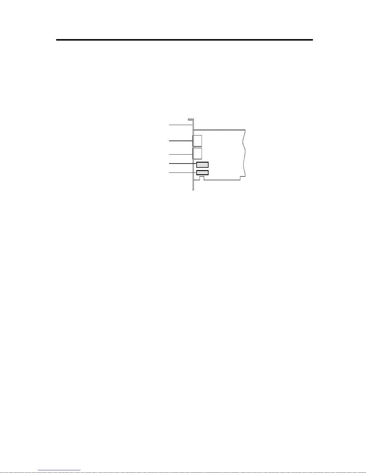
The jacks on your modem card can be seen in Figure 1-1.
Telephone Line Jack
The Telephone Line jack allows you to connect a telephone line for
data transmission and faxing of documents. If your card is a voice
model, the voice mail feature can be used as well.
Phone Jack
The Phone jack allows you to connect a phoneset to the card.
This jack is found only on modem cards sold for use in countries that
follow the United States’ standard.
Mic and Speaker Jacks
These jacks allow you to connect an external microphone and
speakers for use with voice mail and speakerphone features.
(found on those models that support voice and speakerphone)
Figure 1-1:
The jacks on your modem card.
Telephone Line jack
Phone jack
Rear panel
Mic
Speaker
Page 12
Setting Up the Modem 2-1
2
Setting Up the Modem
This chapter guides you through the process of installing your modem.
It is organized as follows:
❑
Installing the Modem
❑
Connecting Telephone Line and Phoneset
Inst alling t he Modem
Installing the modem card in your system is simple. Follow the
instructions carefully.
Telephone Line jack
Phone jack
Rear panel
Mic
Speaker
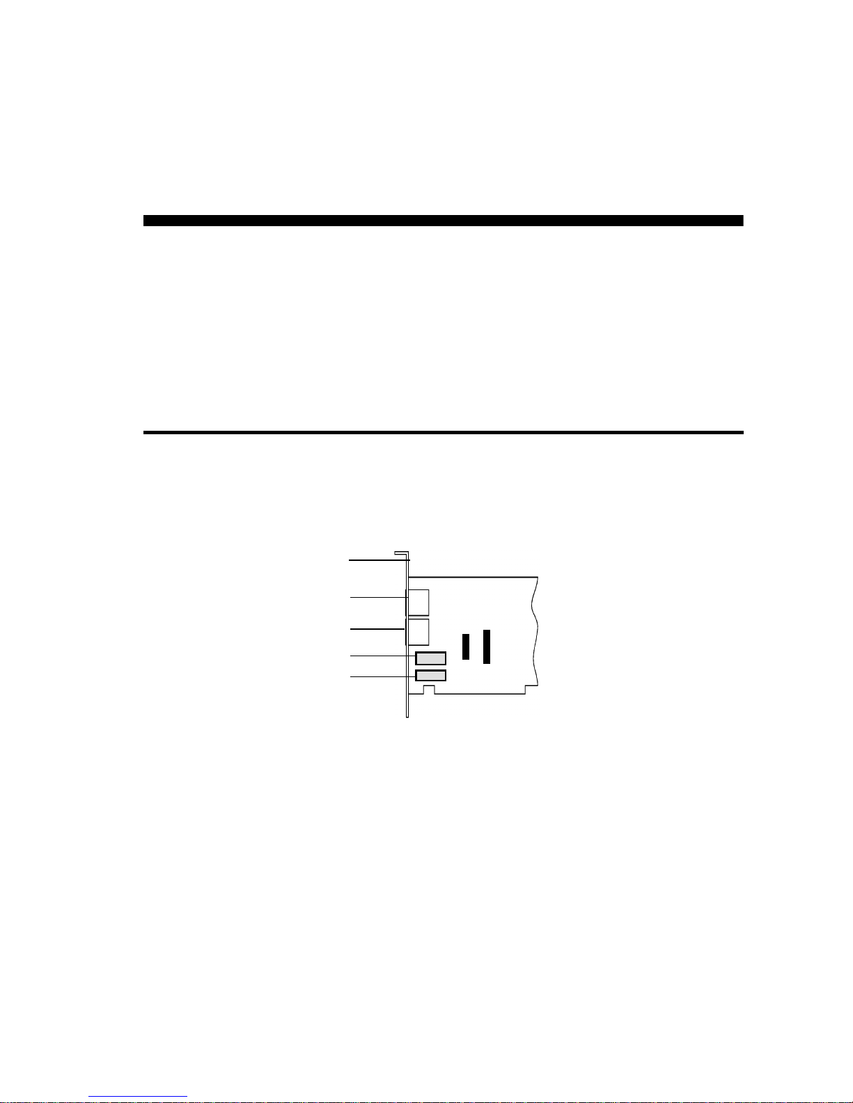
Figure 2-1: Modem Jumpers
(JP5 and JP4 only on those models that
support TAD and Sound Blaster Connector)
JP4
SB
JP5
TAD
Page 13
2-2 Setting Up the Modem
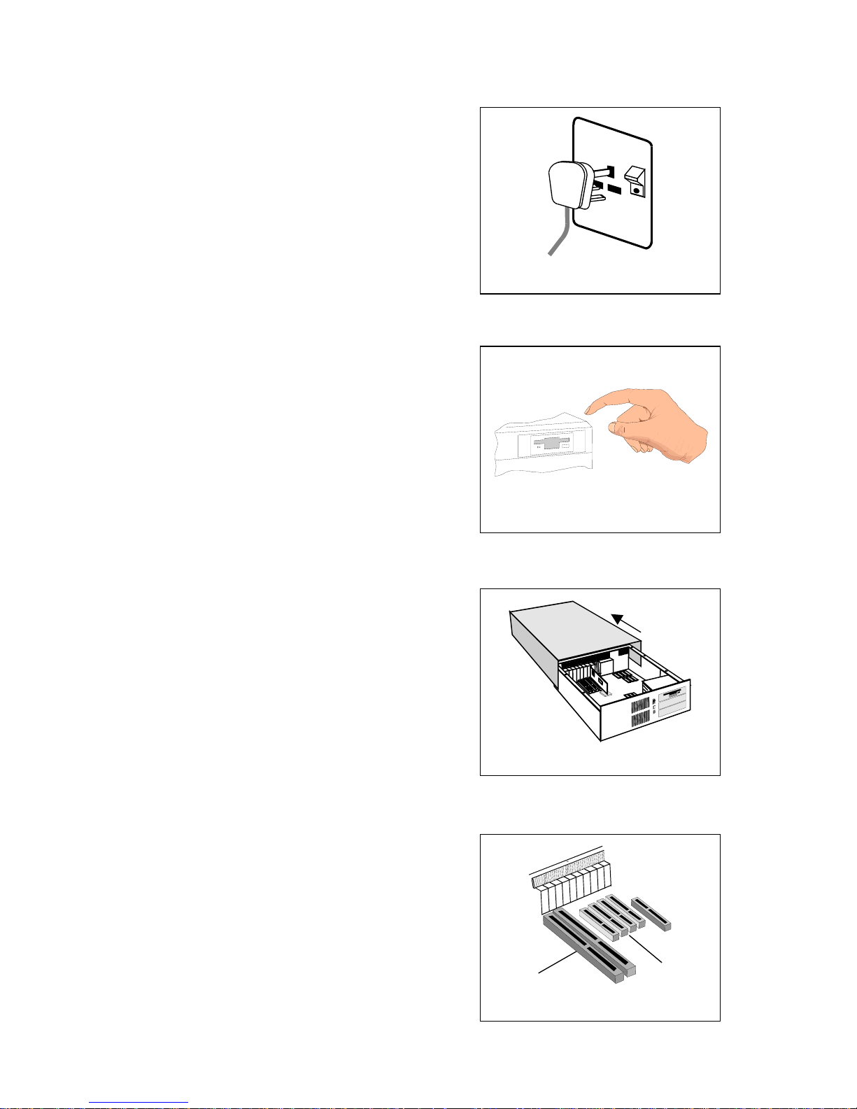
1. Switch off your system
and all peripheral devices.
Unplug the power cord
from the wall outlet.
(The power cord and wall
outlet shown may be
different in your country.)
2. T ouch a metal plate on your
system to ground yourself
and discharge any static
electricity.
3. Remove the cover from
your system.
4. Find a free PCI expansion
slot in your system.
Figure 2-2
Figure 2-3
Figure 2-4
Figure 2-5
ISA slot
PCI slot
Page 14
Setting Up the Modem 2-3
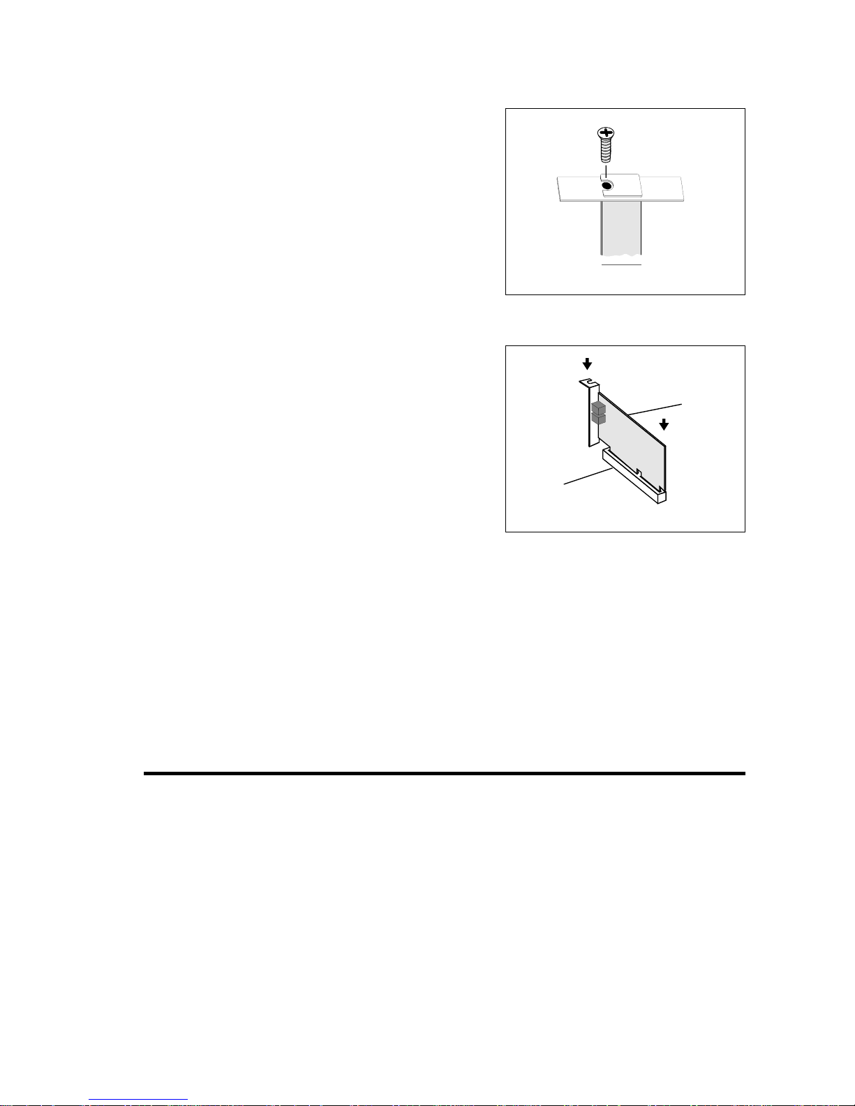
5. Remove the metal plate
from the slot you have
chosen. Retain the screw
and put the removed blank
plate aside.
6.
Align your card’s PCI slot
connector with the
expansion slot and press
the card gently and evenly
into the free slot as shown
in Figure 2-7.
Ensure that the bus
connector has been pressed
in as far as it will go and is
sitting firmly inside the
expansion slot.
7. Secure the card to the expansion slot with the screw you
removed from the blank metal plate.
8. Replace the cover of your system.
Connect ing Telephone Line and Phoneset
Before using the modem, you need to connect your telephone line and
phoneset to the card. T o ensure that the modem works properly, know
that:
❑ Y our modem cannot be used on “party lines”, nor can it be used
on toll or coin-operated lines.
Contact your local telephone company for help if you are not
sure about the suitability of your telephone line.
Figure 2-6
Figure 2-7
PCI slot
Modem
card
Page 15
2-4 Setting Up the Modem
❑ This modem is intended for use on an analog telephone line,
also called a POTS (Plain Old Telephone Service) line. This
modem cannot be connected directly to a digital telephone line,
such as those commonly found in businesses.
Either obtain an analog line or an analog converter compatible
with the telephone line you are using.
❑ Certain optional telephone features, such as a “message
waiting” light or call waiting, are not compatible with this
modem and should not be present on the telephone line on
which the modem is to be used. Call waiting may be selectively
disabled (in most areas) on outgoing calls. If call waiting is
present, it may interfere with data being transferred through the
modem.
To connect the telephone line and phoneset to your modem:
1. Locate the most convenient telephone wall outlet.
2. If a phone is already connected to it, unplug the telephone cable
from the wall outlet.
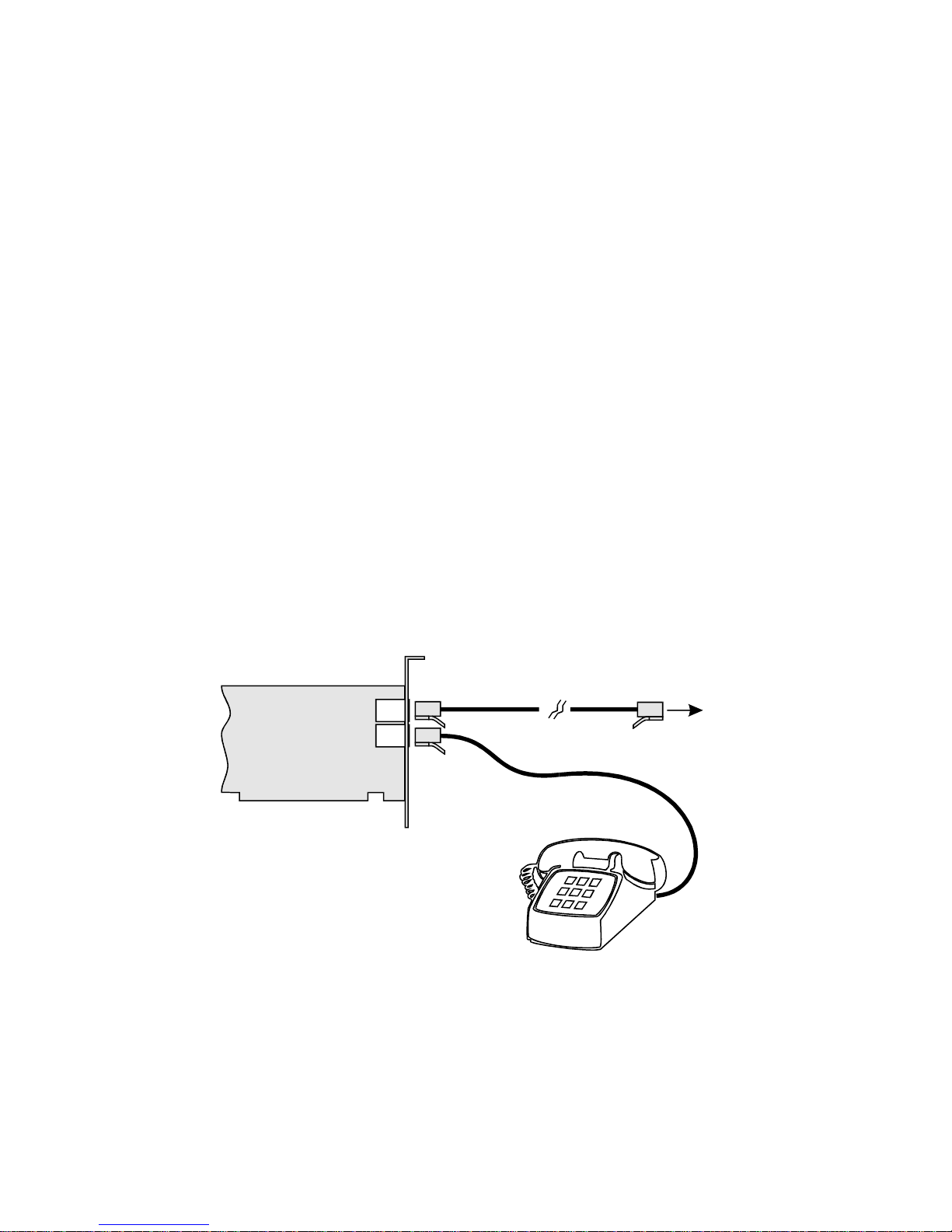
3. See Figure 2-8 for how to connect the telephone line and
phoneset to the modem.
i. Connect the telephone cable from the phoneset to the Phone
jack of the modem.
ii. Connect one end of the telephone cable provided, to the
wall outlet and the other end to the Telephone Line jack of
the modem.
Figure 2-8: Connecting telephone line and phoneset to your modem.
Telephone Line
Phone
Telephone cable provided
To wall outlet
Phone Set
Page 16

Installing Software in Windows 95/98 3-1
3
Installing Software in
Windows 95/98
This chapter provides instructions to install the software and test your
installation in Windows 95/98.
If you have not installed Windows 95/98, please do so before you
proceed. To install the modem software, have the Windows
Installation CD ready to install the required drivers.
Installing Sof tware
To install your modem drivers:
1. Switch on your system to allow the operating system to detect
modem card.
2. If you are prompted for the Windows Installation CD, insert it
into your CD-ROM drive and click OK.
3. Specify the WIN directory (for example, D:\WIN95) to install
the drivers.
Page 17
3-2 Installing Software in Windows 95/98
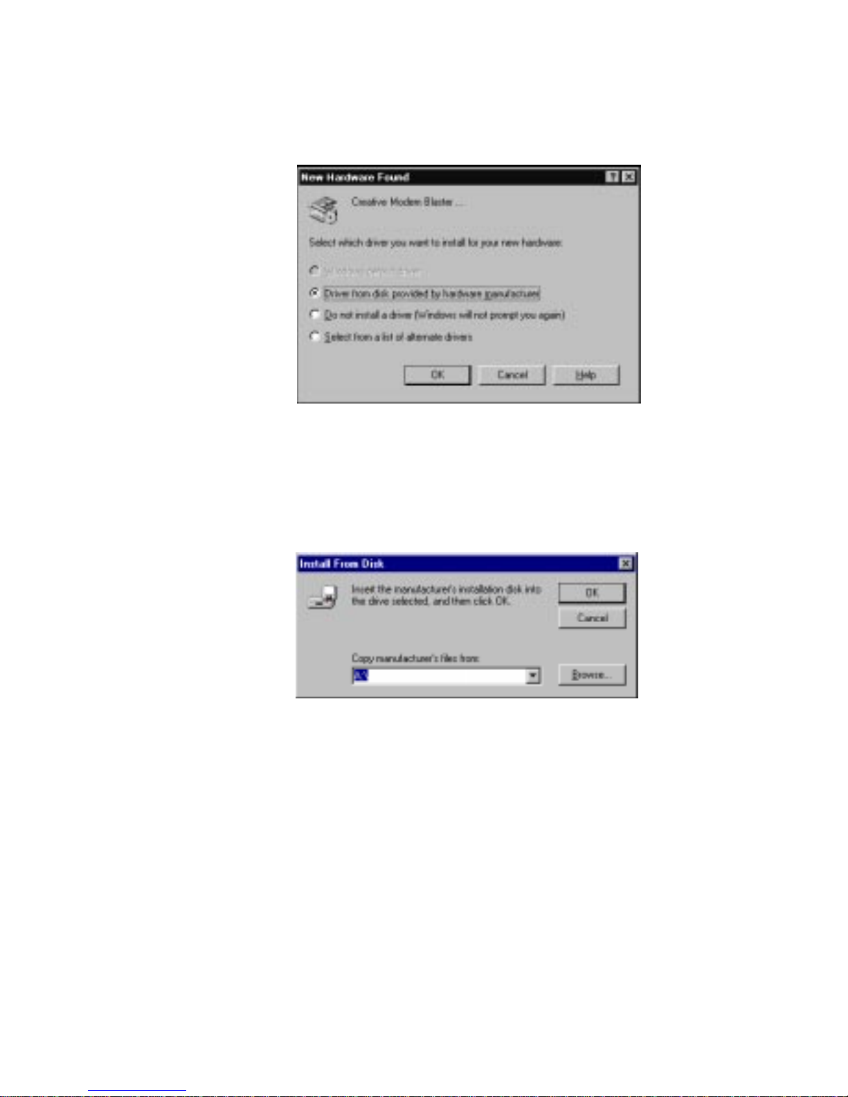
4. When the modem interface on your card is detected,
a dialog box similar to the one in Figure 3-1 appears.
5. Select Driver From Disk Provided By Hardware Manufacturer
and click the OK button.
The Install From Disk dialog box similar to Figure 3-2 appears.
6. Insert the Modem Blaster Installation CD or Diskette.
7. Type or click the Browse button and point to the drive
containing the CD or Diskette.
For example, if the CD or Diskette is in drive D, type D: and
click the OK button.
8. Follow the instructions on the screen to complete the
installation.
Figure 3-1: The New Hardware Found dialog box.
Figure 3-2: The Install From Disk dialog box.
Page 18
Installing Software in Windows 95/98 3-3
Testing the Installation
After you have set up your modem, run the following test to ensure
that your card has been properly installed. To test your modem:
1. Click the Start button on the taskbar, point to Settings and then
click Control Panel.
The Control Panel window appears.
2. Double-click the Modems icon.
The Modems Properties dialog box appears.
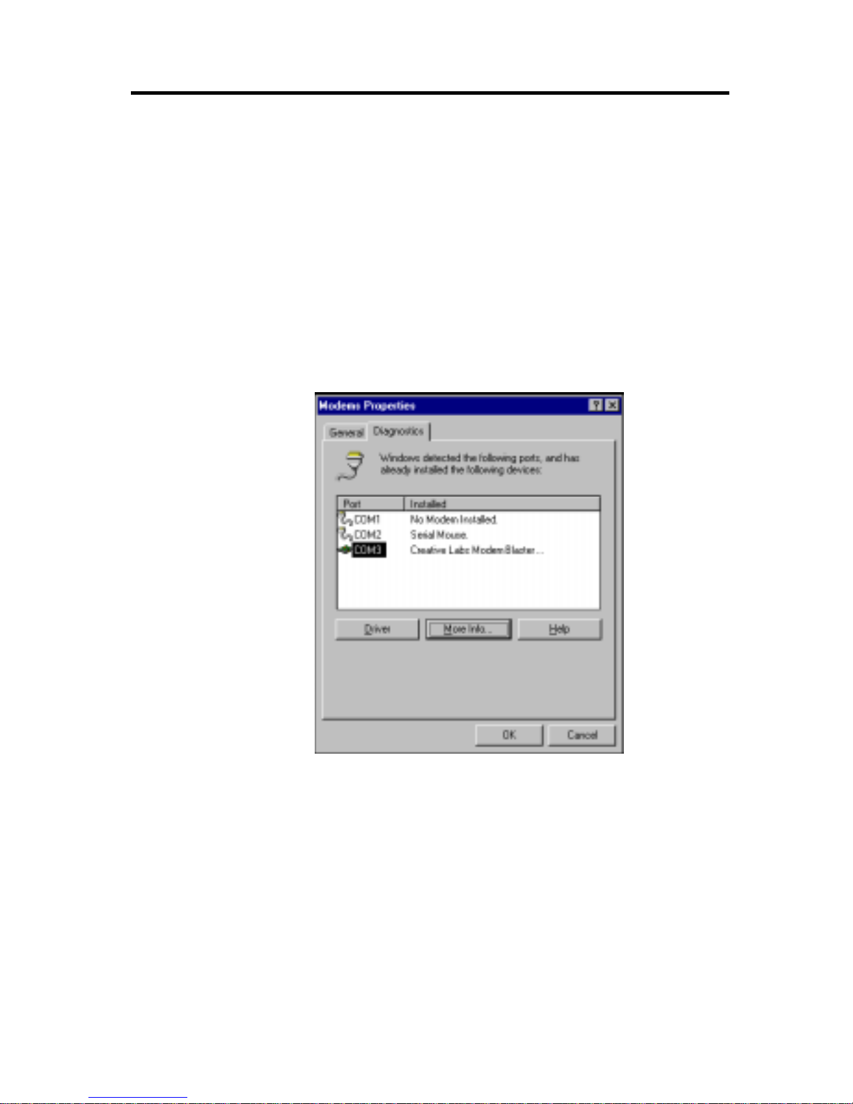
3. Click the Diagnostics tabbed page.
The dialog box similar to Figure 3-3 appears.
4. Select the COM port that has been assigned to your modem.
5. Click the More Info button to display the response status of
your modem.
If your modem is not responding, it may be due to a conflict
between the modem and another peripheral device. T o resolve
the conflict, you must change the settings of your modem
(see the “Resolving Hardware Conflicts” section on page B-4).
Figure 3-3: COM ports assigned to the different devices.
Page 19

Page 20
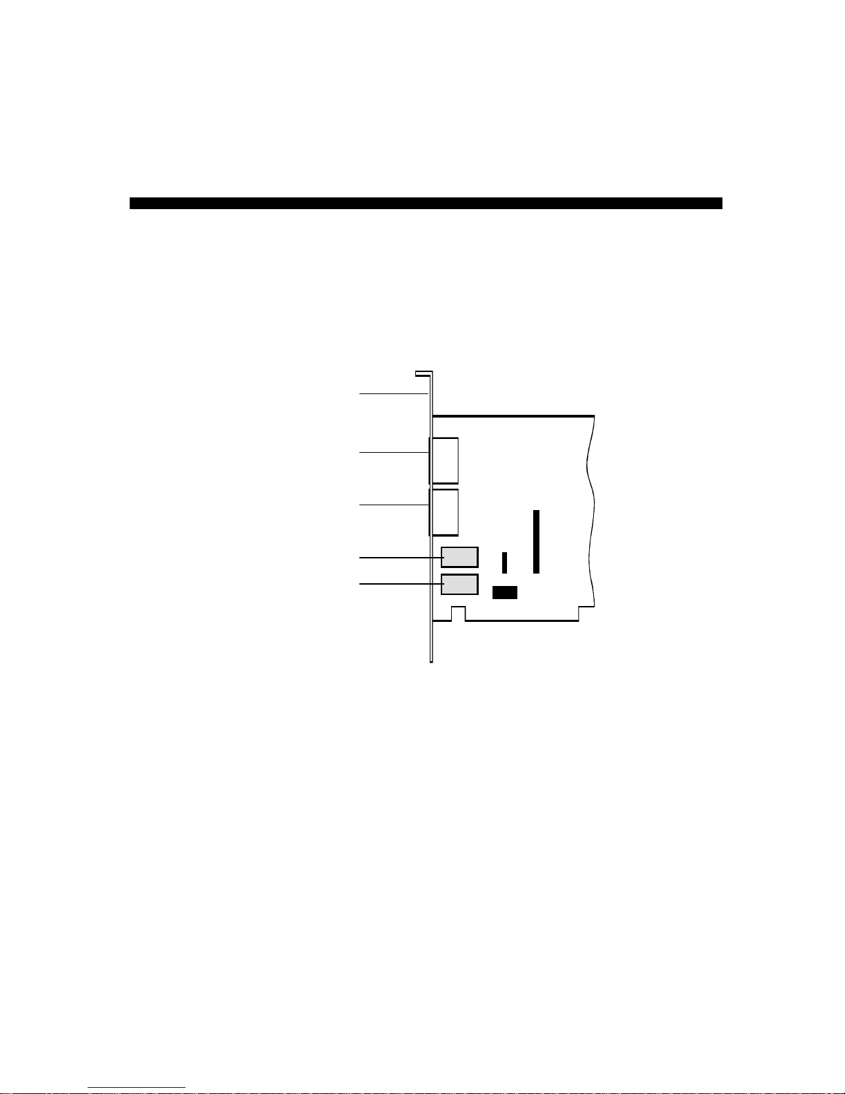
Connectors and Settings 4-1
4
Connectors and Settings
This chapter provides information on your modem card connectors
and jumpers.
JP4 SB (Sound Blaster) connector (found only on those models
that support Sound Blaster Interface):
This connector is used to
connect the modem directly to a Sound Blaster card. Sound Blaster is
the most popular and highest performance PC sound card in the
industry. By connecting the modem directly to a Sound Blaster card,
you will enjoy the highest performance and quality sound experience
when connected to the internet or other users. Simply use a 10 pin
cable to connect directly to your Sound Blaster card.
Figure 4-1: Connector & Jumper Locations.
Telephone Line jack
Phone jack
Rear panel
Mic
Speaker
JP4 SBJP5
TAD
JP6 & 7
Page 21

4-2 Connectors and Settings
JP5 TAD (Telephone Answering Device) (found only on those
models that support Sound Blaster Interface): Some sound cards
support a T AD connection from the modem directly to the sound card
(it has less functionality than the SB connector). If your sound card
supports this function you can connect a 4 pin cable from the TAD to
your sound card. Please ensure Pin 1 is connected together on both
cards.
JP6 & 7 (Internal Speaker) (found only on those models that
support Sound Blaster Interface): To activate internal speaker,
place jumper shunts on pins 2 & 3 of both JP6 and JP7. T o disable the
internal speaker remove all jumper shunts from JP6 and JP7.
Page 22
Uninstalling the Modem in Windows 95/98 5-1
5
Uninstalling the Modem in
Windows 95/98
This chapter provides instructions to uninstall the modem in
Windows 95/98. To uninstall your modem:
1. Click the Start button on the taskbar, point to Settings and then
click Control Panel. The Control Panel window appears.
2. Double-click the Modems icon.
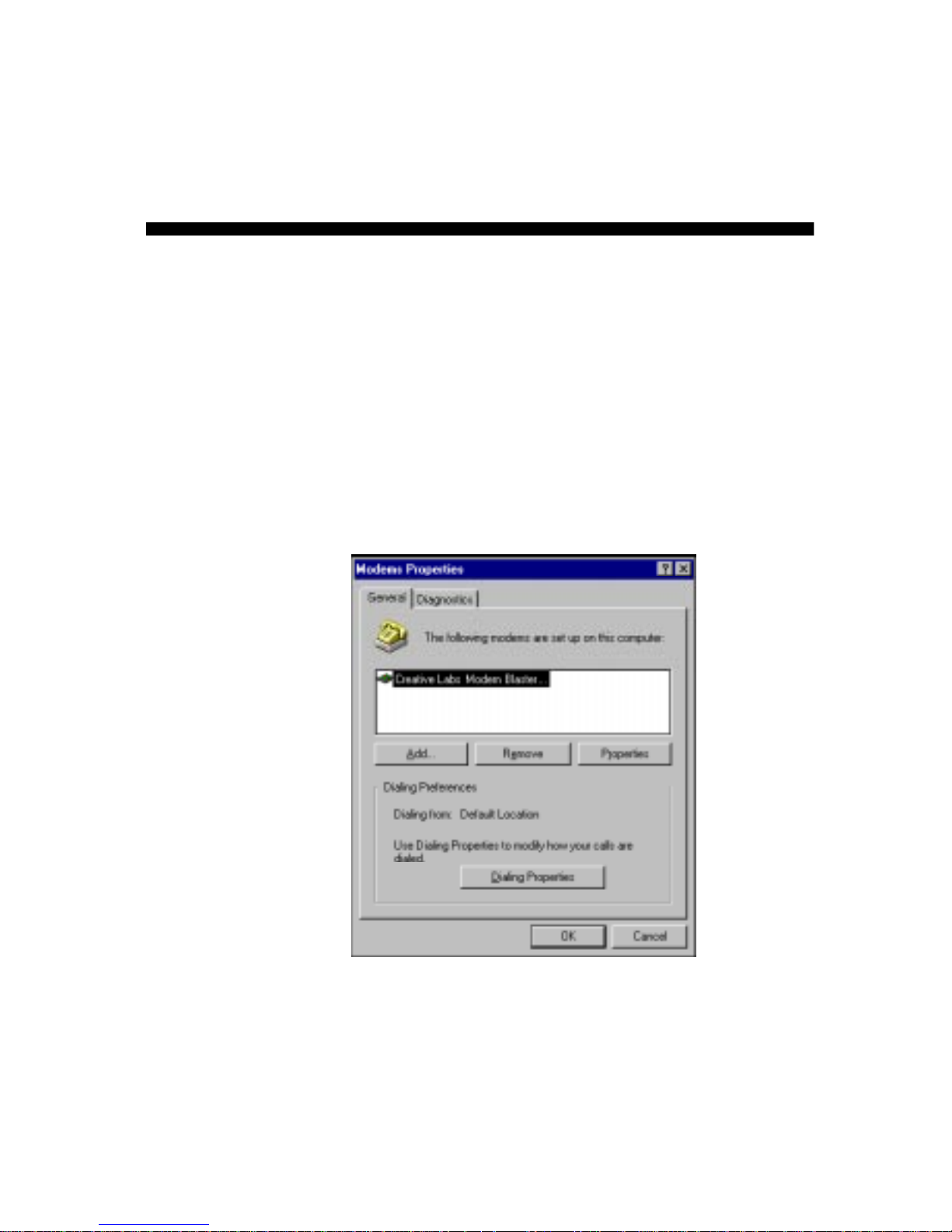
The Modems Properties dialog box similar to Figure 5-1
appears.
3. Select the modem, click the Remove button, then Close.
4. Exit from Windows.
5. Switch off your system and remove the modem card from your
system.
Figure 5-1: The Modems Properties dialog box.
Page 23

Page 24
General Specifications A-1
A
General Specifications
This appendix lists the general specifications of your modem.
Plug and Play
❑
PCI specification compliant.
❑
Plug and Play resources.
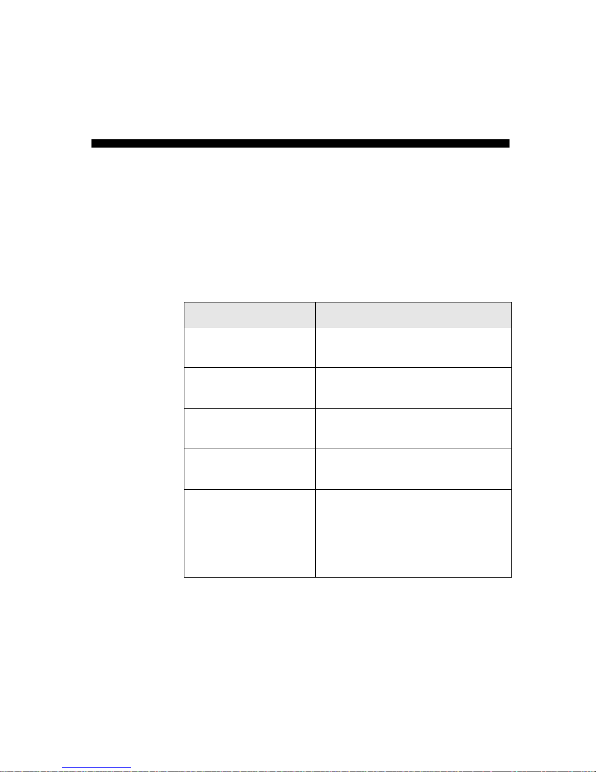
Table A-1:Plug and Play Resource Information.
Dependent functions Resource Information
Choice 1
COM 3
I/O Port: 3E8 to 3EF
IRQ: 3, 4, 5, 7, 9, 10, 11 or 15
Choice 2
COM 4
I/O Port: 2E8 to 2EF
IRQ: 3, 4, 5, 7, 9, 10, 11 or 15
Choice 3
COM 2
I/O Port: 2F8 to 2FF
IRQ: 3
Choice 4
COM 1
I/O Port: 3F8 to 3FF
IRQ: 4
Choice 5
Free-For-All
I/O Port: 2A0 to 2A7,
2A8 to 2AF,
...
2D8 to 2DF
IRQ: 3, 4, 5, 7, 9, 10, 11 or 15
Page 25

A-2 General Specifications
Data Features of the Modem
❑ Integrated data, fax, and voice mail modem.
❑ 56,000/54,000/52,000/50,000/48,000/46,000/
44,000/42,000/40,000/38,000/36,000/34,000
❑ 33,600/28,800/26,400/24,000/21,600/19,200/16,800/14,400/
12,000/9,600/7,200/4,800/2,400/1,200/300 bps data speeds.
Compatibility with the following data modem standards:
- V.34, V.FC, V.32bis, V.32, V.23, V.22bis, V.22A/B, and
V.21; Bell 212A and 103.
- V.42 LAPM and MNP2-4 error correction.
- V.42bis and MNP5 data compression.
❑ Compression, line control, and error control are implemented
in hardware. Therefore, no special drivers or libraries are
needed to take advantage of the higher speeds and data
reliability.
❑ Automatic dial and answer capabilities.
Note: Due to line conditions and FCC regulations your data rate may
be lower. Current FCC regulations limit download to 53 Kbps max.
Fax Features of the Modem
❑ Supports Class 1 fax commands.
❑ Fax speeds up to 14400 bps for send and receive.
❑ Compatibility with the following fax modem transmission
standards:
- V.17 (14400 bps)
- V.21 Channel 2 (300 bps)
- V.27ter (7200 bps)
- V.29 (9600 bps)
Voice and Speakerphone Features of the Modem (available only
on models that support these features)
❑ Ability to record and play voice messages over the telephone
line.
❑ Multiple mailboxes using included communications software.
❑ High performance speakerphone.
Page 26

General Specifications A-3
Video Conferencing Support
❑ Supports V.80 standard to allow high performance video
conferencing over standard phone lines and the internet. V ideo
conferencing standards are H.324 and H.323.
Sound Blaster Interface (available only on models that support
this feature)
❑ This connector is used to connect your modem directly to a
Sound Blaster card. Sound Blaster is the most popular and
highest performance PC sound card in the industry. By
connecting your modem directly to a Sound Blaster you will
enjoy the highest performance and quality sound experience
when connected to the internet or other users.
Telephone Answering Device (TAD) (available only on models
that support this feature)
❑ Some sound cards support a T AD connection from the modem
directly to the sound card (it has less functionality than the
Sound Blaster Interface).
Page 27

Page 28

Troubleshooting B-1
B
Troubleshooting
This appendix provides some tips and strategies for resolving some of
the problems you might encounter with your card either during
installation or normal use.
Problems with Modem
Problem
The modem fails to accept commands to dial or to
answer a call.
Cause
An improper telephone line connection.
Solution
Make sure the telephone cable is attached to the
T elephone Line jack, and that the phoneset is connected
to the Phone jack on your card.
Also check that all devices are turned on.
Problem
Interference on the telephone line that is connected to
the modem.
Cause
It might be due to interference from a power source,
monitor, printer, or other computer cables.
Solution
Try moving the telephone line away from any power
source, monitor, printer, and other computer cables.
Page 29

B-2 Troubleshooting
Problem Cannot connect to internet at 56,000 bps speeds.
Cause It might be due to line conditions in your area. Due to
FCC regulations and/or line conditions it is not always
possible to achieve the maximum data rate.
Solution Try moving the telephone line away from any power
source, monitor, printer, other computer cables and
remove other telephone equipment from the line.
Problem The modem or communications software fails to detect
that the remote user has hung up.
Cause The modem and communications software rely on the
dial tone, busy tone, or silence period to detect a remote
user has hung up. This detection may fail due to one of
the following reasons:
❑ Your local telephone system does not generate the
dial or busy tone when the remote user hangs up.
❑ The silent period, for the modem or
communications software to detect that the remote
user has hung up, is not long enough.
❑ The modem or communications software cannot
detect a different dial or busy tone.
For example, if you are connecting to a PABX
system, the dial or busy tone generated is different
from the usual dial or busy tone.
Solution Prompt the user to respond.
This may however result in a long delay before the
communications software responds to the remote user
hanging up. To minimize this delay, try to modify the
following settings:
❑ Voice message recording time.
❑ The number of prompts.
❑ The time to wait for a response after prompting.
Page 30

Troubleshooting B-3
Problem Poor sound quality when using communications
software.
Cause Some 32-bit sound and communications software
require a Unimodem V file. Windows 95 normally
installs this file. However, in some installations the file
is missing and that could affect sound quality when
32-bit software is used.
Solution Try to install the Unimodem V file as follows:
1. Go to www.digicom.sys download section.
Download the Unimodem V file.
2. Use Windows Explorer and copy the file
‘unimodemv.exe’ to your Windows directory.
3. Run ‘unimodemv.exe’ - this can be done by
double-clicking on the file under Windows
Explorer.
4. Restart your computer to activate ‘unimodemv .exe’.
Page 31

B-4 Troubleshooting
Resolving Hardware Conflict s
Hardware conflicts occur when two or more peripheral devices
contend for the same signal lines or channels. Conflicts between your
modem and another peripheral device might be due to the settings of
the I/O addresses or IRQ lines.
Resolving Conflicts in Windows 95/98
T o resolve conflicts in Windows 95/98, run Device Manager to change
the resource settings of your modem or the conflicting peripheral
device in your system.
To run Device Manager:
1. Right-click the My Computer icon on your Windows 95/98
desktop.
2. Select Properties.
The System Properties dialog box appears.
3. Click the Device Manager tab.
A list of system devices is displayed.
4. Double-click Modem.
5. Select your modem and click Properties.
The Properties dialog box of modem appears.
6. Click the Resources tab.
7. Select the Use Automatic Settings check box.
If this check box is already selected, you need to go to the
Properties dialog box of the conflicting peripheral device and
select the same check box there.
8. Reboot your system to allow Windows 95/98 to reassign
resources to your modem and/or the conflicting peripheral
device.
If you are unsure of the settings of any conflicting peripheral
devices, you can isolate the source of the problem by
temporarily removing all devices (except your modem and
essential devices such as the disk controller). After that, add the
devices back one at a time until the device that is causing the
conflict is found.
Page 32

Creative Labs, Inc.
Creative Technology Ltd
1901 McCarthy Boulevard
Milpitas CA 95035
31, International Business Park
Creative Resource
Singapore 609921
Printed in Singapore
 Loading...