

Page 1

CD ROM Upgrade
4X CD-ROM Drives
User Guide
On-line Version
Page 2

CD-ROM UPGRADE
Creative GCD-R542B CD-ROM Drive
User’s Guide
Information in th is doc um ent is subject to change withou t notice and does not represent a
commitment on the part of Creative Technology Ltd. The software described in this document
is furnished under a license agreement and may be used or copied only in accordance with the
terms of the license agr eement. It is against the law to copy the software on any other medium
except as specifically allowed in the license agreement.
The licensee may ma ke one copy of the software for backup purposes. No part of this manual
may be reprodu ce d or transmitted in any form or by any means, electr oni c or mechanical,
including photo copying and recording, for any purpose without the written pe rm issi on of
Creative Technology Ltd.
Copyright 1995 by Creative Technology Ltd . All rig hts reserved.
Version 1.0
August 1995
Sound Blaster is a regi ste red trademark of Creative Technology Ltd.
Sound Blaster 16 is a trade mark of Creative Technology Ltd.
IBM is a registered trademark of International Business Machines Corporation.
MS-DOS is a registe red trademark and Windows is a trademark of Microsoft Corporation.
All other products are trademarks or registered trademarks of their respective owners.
Page 3

Regulatory Information
The following sec tions consist the noti ce for the USA and Canada.
Notice for the USA
FCC Part 15: This equipment has been tested and found to comply with the limits for a Class B
digital device, pursuant to Part 15 of the FCC Rules. These limits are designed to provide
reasonable protect ion against harmful inte r f erence in a res idential installation. This equipm ent
generates, uses, and c an radi ate radio frequency energy and , i f not inst alled and used in
accordance with the instruction s , may cause ha rmful interf erence to radio communications.
However, there is no guarantee that interference will not occur in a particular installation. If this
equipment does c ause harmful interference to rad io or television reception, whic h ca n be
determined by turning the equipment off and on, the user is encouraged to try one or more of the
following measure s:
Reorient or relocate the receiving antenna.
❑
Increase the separation bet w een the equipment and receiver.
❑
Connect the equi pment into an outlet on a circuit different from tha t to which the
❑
receiver is connected.
Consult the dealer or an experienced radio/TV technician for help.
❑
Caution
To comply with the limits for the Class B digital device, pursuant to
Part 15 o f the FCC Rules , this device must be installed in computer equip ment certif ied to
comply with the Class B limits.
All cables used to connect the computer and peripherals must be shielded and grounded.
Operation with non-certified computers or non-shielded cables may result in interference to radio
or television reception.
Modifications
Any changes or modifications not expressly app rove d by the grantee of this devic e co uld void
the user’s authority to operate the device.
Notice for Canada
This apparatus complies with the Class “B” limits for radio interference as specified in the
Canadian Department of Communications Radi o Interference Regulation s.
Cet appareil est conforme aux normes de CLASSE “B” d’interference radio tel que spe’cifie’ par
le Ministère Canadi en des Communications dans les règle ments d’interfe’rence radio.
ii
Page 4

Safety Information
CAUTION: This CD-ROM is intended to be installed by the user in a CSA/TUV/UL
certifie d/listed IBM A T or compatible personal computers in the manufac turer’ s defined operator
access area. Ch eck the equipment op erating/ins tallation manual an d/or with the equipment
manufacturer to verify/confirm if your equipment is suitable for user-installed application cards.
ATTENTION: Cette CD-ROM est destinée à être instal lé e par l ’utilisateur, dans un ordinateur
compatible certifié CSA/TUV/UL ou listé IBM AT, à l’intérieur de la zone définie par le
fabricant. Consulter le mode d’emploi ou le fabricant de l’appareil pour vérifier ou confirmer si
l’utilis ateur peut y in s taller lui- même des carte s périphériques.
Compliance
This product is in conforminty to the following Council Directive:
Directive 89/336/ EEC, 92/31/EEC (EMC)
❑
iii
Page 5

Introduction
This User’s Guide provides you with information to install and operate
your CD-ROM drive. It also provides you with information to install
and use QuickCD, an application that allows you to play au dio CDs in
DOS and Windows.
Before Y ou B egin
Before you set up your package, please read the following carefully:
❑ Checking System Requirements
❑ Obtaining Latest Information
❑ Making a Copy of Your Diskette
Checking System Requirements
The following are the system requirements:
❑ A 386SX or compatible computer (486SX recommended).
❑ 720 Kilobytes (KB) of hard disk space for the software.
❑ MS-DOS version 5.0 or later.
❑ Windows 3.1 or later.
❑ An audio card with IDE CD-ROM in terface, an IDE CD-ROM
interface card, or any device with an IDE interface.
Obtaining Latest Information
The README.TXT file on the diskette labeled CD-ROM Installation
Disk contains the latest information and changes not available at the
time of printing. Please read the file before you continue.
To view the file:
1. Insert the CD-ROM Installation Disk into drive A or B of your
computer.
2. Type A:README (or B:README) and press <Enter>.
ix
Page 6

Making a Copy of Your Diskettes
If you have not made a copy of the origi nal diskettes, you shou ld do so
before installing the software in your system. Store your original
diskettes in a safe place.
Using this Guide
This guide is arranged as follows:
Chapter 1, “Knowing Your CD-ROM Drive”
Before you install your drive, you should read this chapter to become
more familiar with your drive. This chapter acquaints you with the
various components and features of your CD-ROM drive. This
chapter is especially helpful if you are new to CD-ROM drives.
Chapter 2, “Setting Up Your CD-ROM Drive”
After you have acquired a general understanding of your CD-ROM
drive, you will be able to set up your CD-ROM drive easily and
quickly. This chapter shows you how to install the drive and run the
test program to ensure that your installation is successful.
Chapter 3, “Using QuickCD”
When you install your CD-ROM drive, the installation progr am copies
QuickCD to your syste m. QuickCD is a program that plays audio CDs
in DOS or Windows. Thi s ch apte r des cri bes h ow to run this pr ogram
in both environments.
Chapter 4, “Doing More with Your CD-ROM Drive”
This chapter comprises several sections to help you get more out of
your CD-ROM drive. These sections provide you with additional
information about your drive e.g., changing the parameters of your
CD-ROM drivers, and connecting additional drives.
Appendix A, “Technical Data”
If you want to know mor e about the physical dimension s, performance
characteristics, and other specifications of your CD-ROM drive, you
can refer to this appendix.
x
Page 7

Appendix B, “Resolving Hardware Conflicts”
The base I/O address or IRQ line of the IDE CD-ROM inter face card
might conflict wi th the I/O address or IRQ line of other devices. Read
this appendix on how to resolve these conflicts by changing your
card’s jumpers.
Appendix C, “Troubleshooting”
If you encounter pr oblems during ins tallation or normal us e, you need
to know how to resolve them. This appendix provides solutions for
some of the problems you might encounter.
Appendix D, “Glossary”
This appendix explains the technical terms used in this guide.
Appendix E, “Technical Support”
If you still cannot resolve a problem after looking at Appendix C, you
can call our Technical Support service. This appendix provides
information on where you can get help.
Document Conventions
This guide follows certain conventions to help you locate and identify
the information that you need. Thes e conventions are described in the
following sections:
❑ Text Conventions
❑ Key Combinations
❑ Icons
Please note that in this guide, installed directory or path refers to the
directory where your CD-ROM’s software is stored (e.g., SBCD).
xi
Page 8
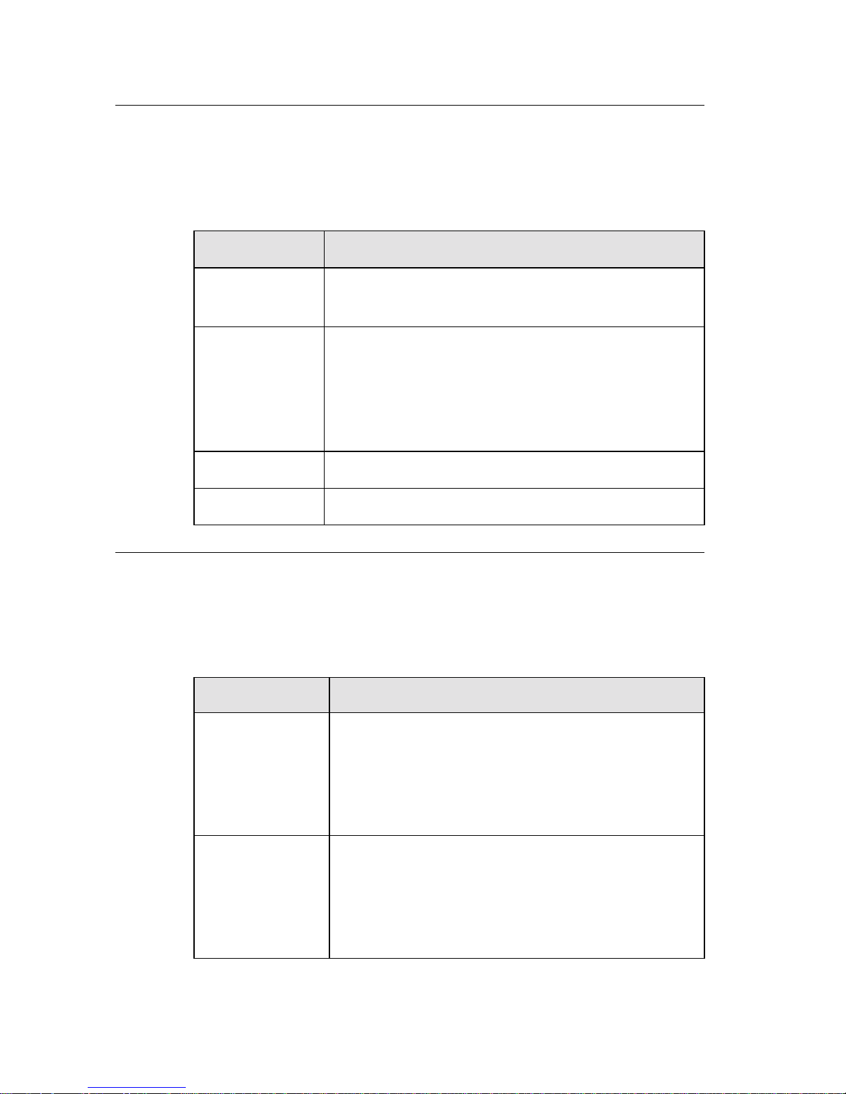
Text Conventions
The following text elements are used to help you distinguish d iffer ent
types of information presented in this guide:
Table i:Text conv entions u sed in th is guide.
Text Element Use
bold
italics
UPPERCASE Directory name, file name, or acronym.
<> Symbols, letters , and key names o n the keyboard.
Key Combinations
In this guide, the following conventions are used to help you identify
different key stroke combinations:
Table ii:Key conventions used in this guide.
Command names, switches, and any text that
must be entered exactly as it appears.
Title of a book. When presented at the DOS
command line, it is a placeholder that represents
information you must provide. This information
usually appears in the parameter listing after the
command is presented.
Combination Use
<Key1+Key2> A plus sign (+) between key names means you
<Key1,Key2> A comma sign (, ) between key names means you
must press the keys at the same time. For
example, “Press <Ctrl+Z>” means press the
<Ctrl> key and hold it down while you press the
<Z> key.
must press the keys in sequence. For example,
“Press <Alt,F>” means press the <Alt> key an d
release it, and then press the <F> key and release
it.
xii
Page 9
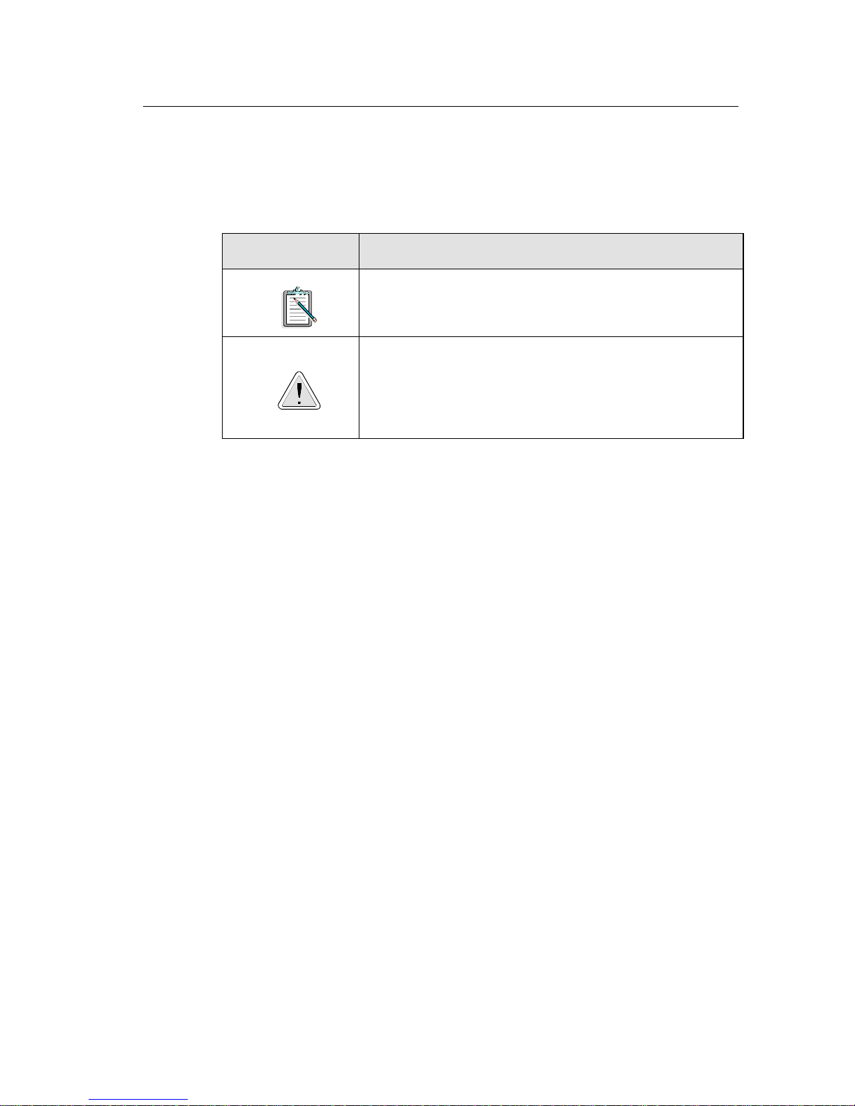
Icons
In this guide, icons are used to highlight areas of text that require your
attention.
Table iii:Icons used in this guide.
Icon Use
Information or inst ructions that must not be taken
lightly a nd should be noted.
Cautions or warn ings that you must pay atten tion
to. Information highlighted by this icon tells you
how to avoid situations such as the risk of not
enough memory or even damag es to your system.
xiii
Page 10

Knowing Your CD-ROM Drive
Your CD-ROM drive is just like a CD player. It allows you to play
audio CDs, skip and stop a track, and eject the CD using software
application (see Chapter 3, “Using QuickCD”).
Furthermore, your drive supports the following features:
❑
Quad Speed Transfer
Your drive can supply a continuous stream of information at
600 KB per second to the PC’s bus. This higher transfer rate
produces better performance when viewing Video for
Windows or QuickTime m ovies and multimedia applications.
❑
CD-ROM Standards
Your drive meets the MPC level 2 requirements for CD-ROM.
It also enables you to read CD-ROM/XA (Extended
Architecture) — a specification that allows you to interleave
data, au dio, and video sectors on a CD.
1
❑
Motorized Tray Loading System
Your drive comes with a motorized tray loading system which
allows you to load your CDs like a CD player.
❑
Multiple Drives Support
You can connect more than one CD-ROM drive to your PC.
For more information on connecting additional drives, refer to
the section “Connecting Additional Drives” in Chapter 4.
The rest of this chapter describes the components of yo ur drive’ s front
and rear panels.
Knowin g Your CD-ROM Drive 1-1
Page 11
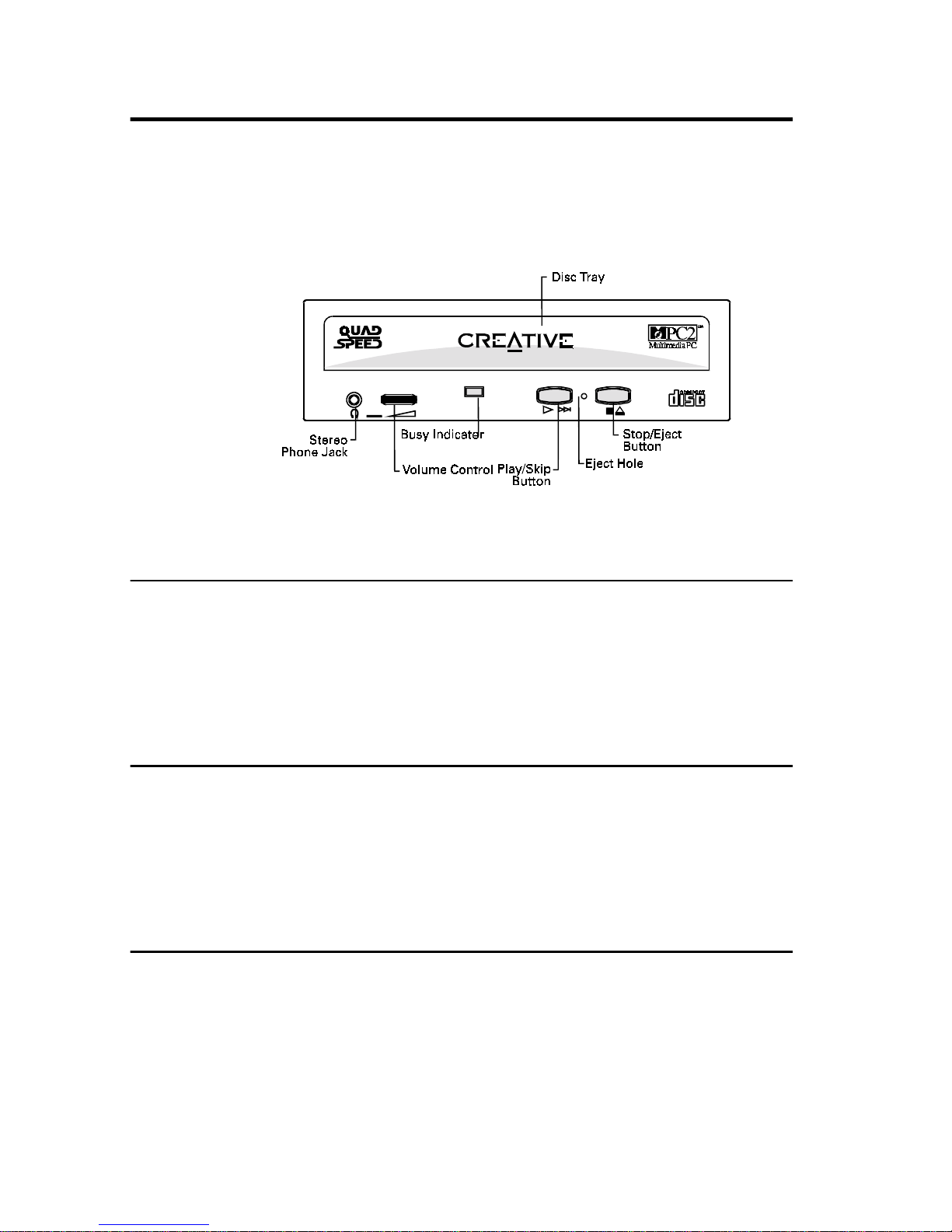
The Drive’ s Front Panel
This section describes the vario us controls on y our drive’s front panel
as shown in Figure 1-1.
Figure 1-1: The front panel of your CD-ROM drive.
Stereo Phone Jack
The Stereo Phone Jack allows you to connect a pair of earphone s to the
drive. It also allows you to connect a pair of powered speakers. If you
are connecting a pair of speakers to your drive, make sure that you
switch on the speakers.
Volume Control
The Volume Control allows you to adjust the volume of your
earphones or powered speakers connected to the front panel Stereo
Phone Jack. This control has no effect on the audio output from
devices (such as speakers) connected to your audio card.
Busy Indicator
The Busy Indicator lights up whenever yo ur drive is reading data from
your disc.
Knowing Your CD-ROM Drive 1-2
Page 12

Play/Skip Button
The Play/Skip button allows you to play audio CDs when the
CD-ROM drive is connected to your system’s power supply. If your
disc tray is ejected and loaded with a audio CD, pressing this button
closes the tray and plays the audio CD.
While your audio CD is playing, you can press this button to skip a
track. If you play a disc that does not contain any audio data, you will
not hear any sound and the Busy Indicator blinks momentarily to
signal the error.
You can operate your CD-ROM drive using controls on the
drive’ s front panel or us ing applications such as QuickCD (see
Chapter 3). If you are using the co ntrols on the fr ont panel, you
cannot use QuickCD. Similarly, if you use QuickCD, you
cannot use the controls.
Eject Hole
The Eject Hole allows you to eject the disc tray if the Eject/Stop button
is disabled by a software or if power failure occurs. Refer to “Disc
Tray” for more information on how to do so.
Stop/Eject Button
The Stop/Eject button stops playing a CD. It also allows you to eject
or close the disc tray when the drive is not playing CD.
The Stop/Eject button will not eject the disc tray if the tray is
locked by software application. To eject the disc tray, q uit the
application before you press the button.
Disc Tray
The disc tray is where you place your CD-ROM or audio CD. To
eject button the tray, press the Stop/Eject button on your drive.
Knowin g Your CD-ROM Drive 1-3
Page 13
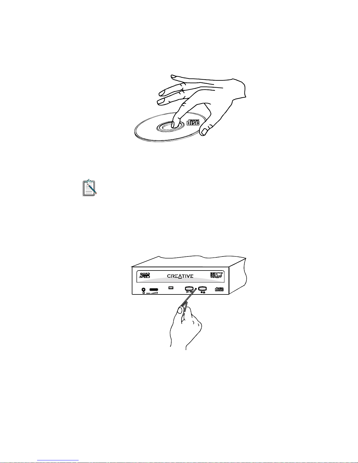
When placing the disc onto the tray, hold the disc by the inner and
outer edges with the disc label facing up as shown in Figure 1-2.
Figure 1-2: Holding a disc.
The disc tray can be locked using the LOCKCD.EXE utility
(see the section “Locking the Disc Tray” in Chapter 4).
When there is a power or system failure, you can eject the disc tr ay by
inserting a straightened paper clip into the Eject Hole and push hard
(see Figure 1-3). Pull the ejected tray out gently as shown in
Figure 1-4.
Figure 1-3: Inserting the straightened pa per clip to eject the tray.
Knowing Your CD-ROM Drive 1-4
Page 14
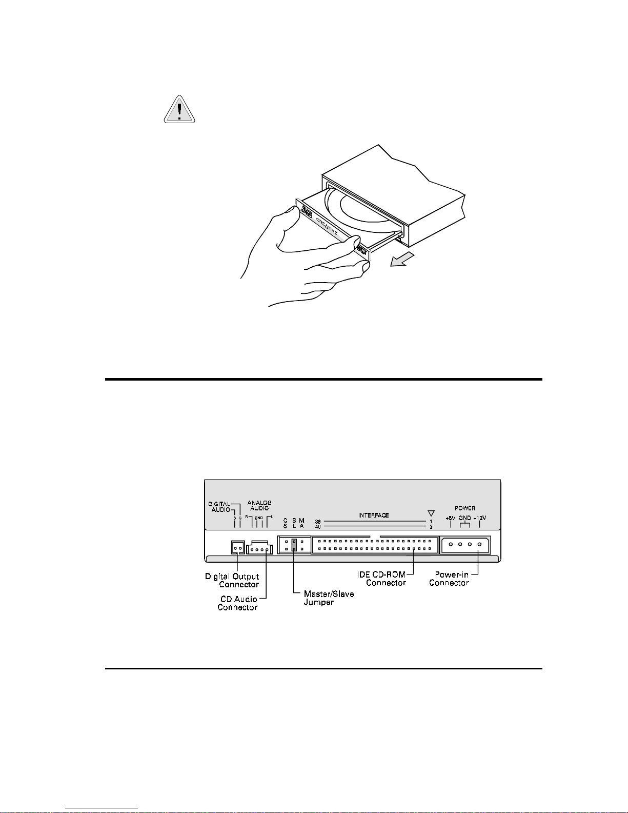
Please refrain from using excessive force to open the tray as
this may damage your drive
Figure 1-4: Pulling out the tray.
.
The Drive’ s Rear Panel
This section provides you with information on the connectors and
jumpers found on your drive’s back panel as shown in Figure 1-5.
Figure 1-5: The rear panel of your CD-ROM driv e.
Digital Output Connector
The Digital Output Connector allows your CD-RO M drive to provid e
digital output for recording to a digital audio tape (DAT) or
professional a udio recording system.
Knowin g Your CD-ROM Drive 1-5
Page 15
CD Audio Connector
The CD Audio Connector al lows you to direct audio output from y our
CD-ROM drive to your audio card when it is connected using a CD
audio cable.
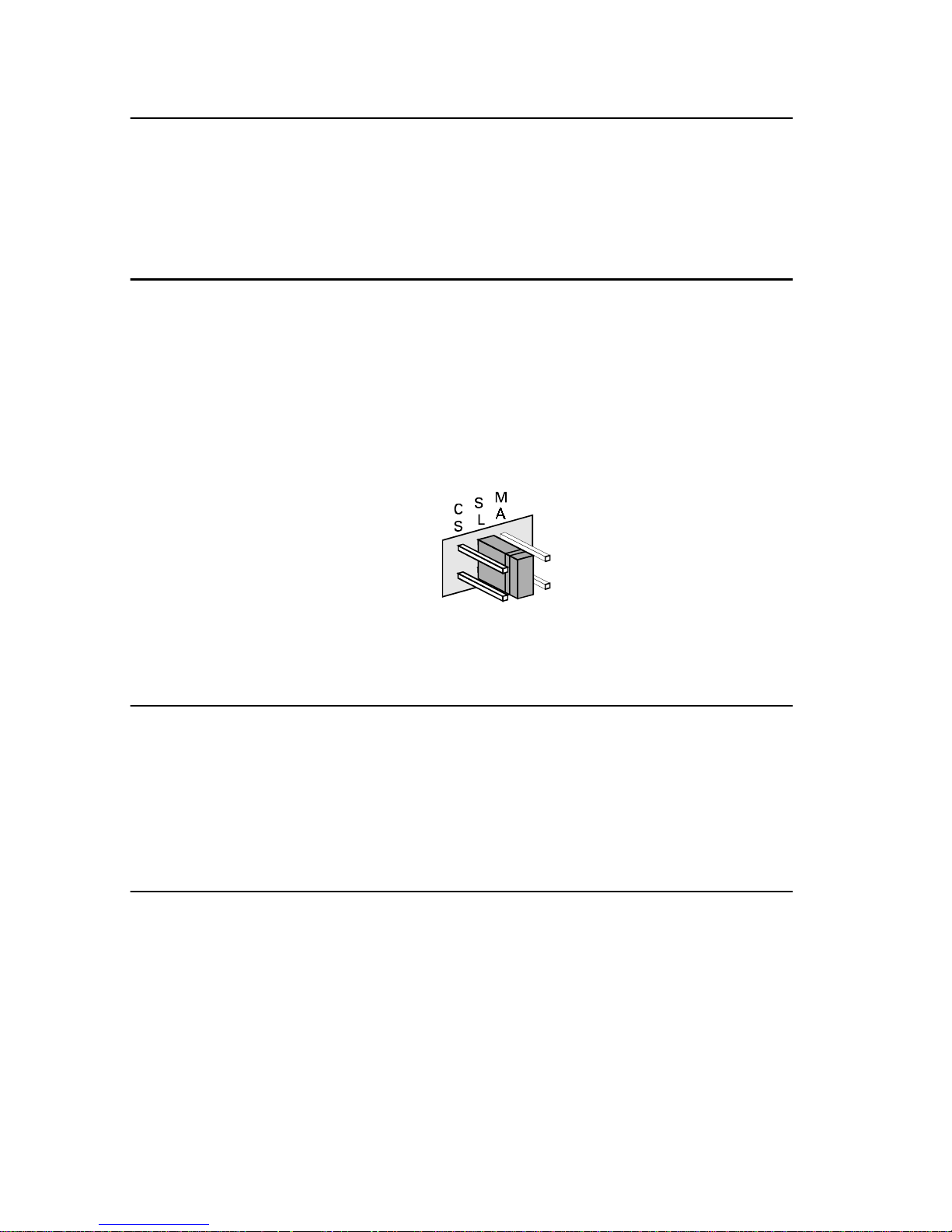
Master/Slave Jumper
The Master/Slave Jumper (see Figure 1-6) allows you to set your drive
as the Master or Slave drive. When you connect more than one drive,
you must set your drive to be either a Master or Slave drive (see the
section “Connecting Additional Drives” in Chapter 4). The jumper
labeled CS is reserved and should not be used.
Figure 1-6: Master/Slave Jumper.
IDE CD-ROM Data Connector
The IDE CD-ROM Data Connector allows data transfer b etween your
CD-ROM drive and various devices when connected using a data
cable. These devices include y our audio card (with an IDE interf ace),
IDE CD-ROM interface card, and hard disk controller card.
Power-in Connector
The Power-in Connector allows electrical power to be directed from
your PC to the drive when connected using a power cable.
Knowing Your CD-ROM Drive 1-6
Page 16
Setting Up Your CD-ROM Drive
This chapter provides you with instructions to set up your CD-ROM
drive. These instructions work:
❑
If you have purchased your CD-ROM drive as a stand-alone
product or in a multimedia upgrade kit.
❑
If you have purchased your CD-ROM drive with a CD-ROM
interface card.
If you are new to CD-ROM drives, we recommend that you
read Chapter 1 before attempting to set up your drive.
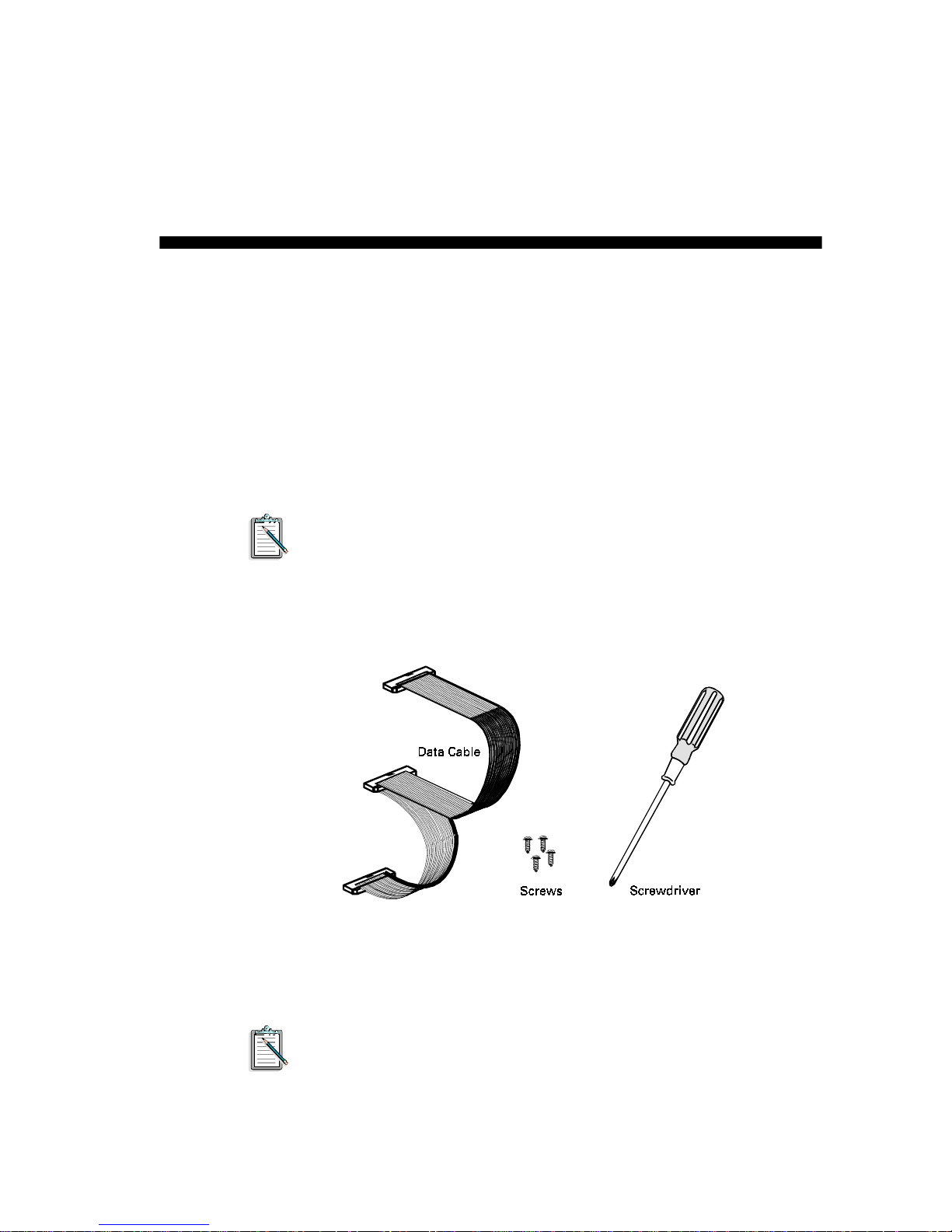
Besides the CD-ROM drive, get the following items ready before
setting up your drive (see Figure 2-1):
2
W e recommend you to use a Philip Number One screwdriver as
it is applicable to most systems. To av oid any damage to your
drive, fasten the drive to your system using the screws
(M3x5mm) provided.
Figure 2-1: Items required for setting up your CD-ROM drive.
Setting Up Your CD-ROM Drive 2-1
Page 17
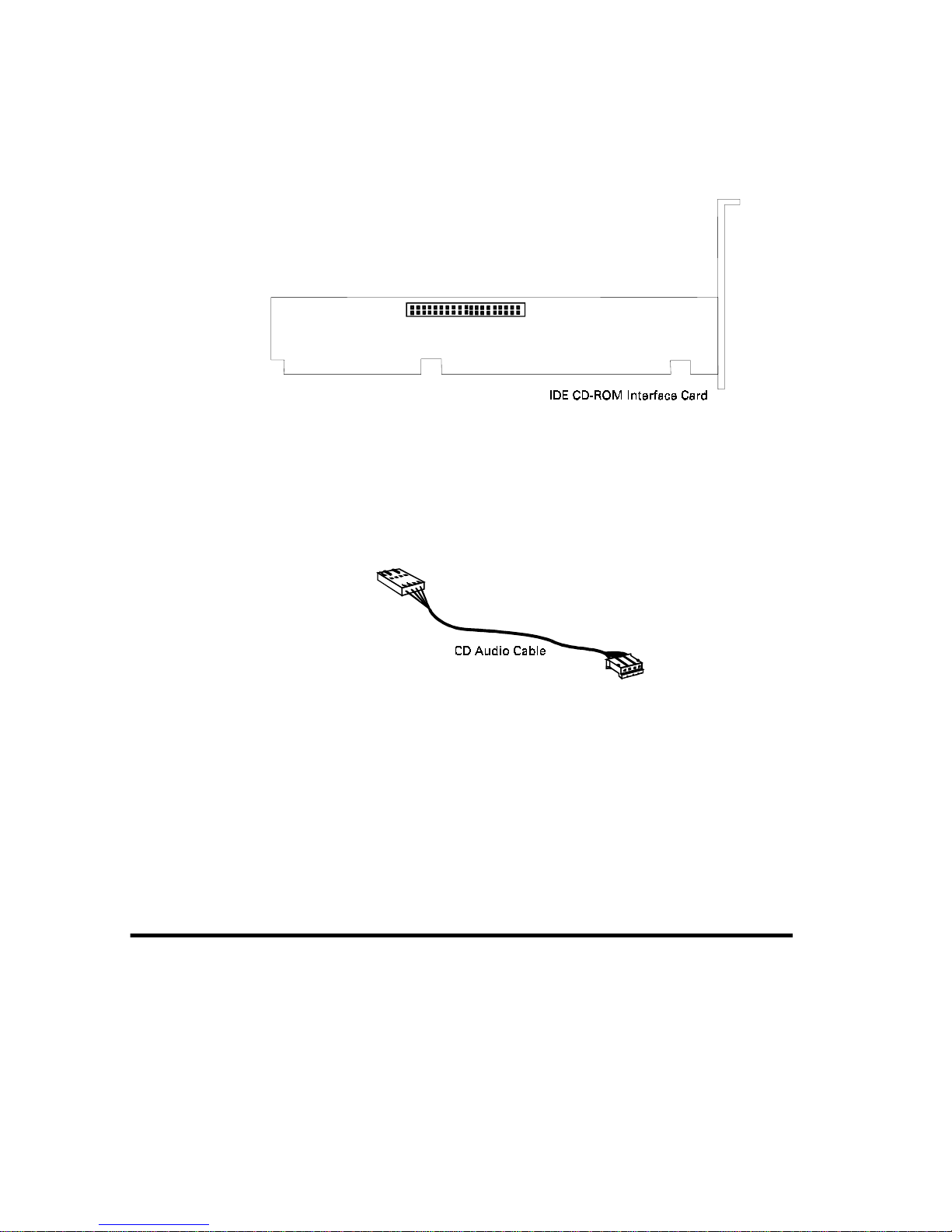
If you have purchased th e drive with an IDE CD -ROM interface card,
get the interface card ready (see Figure 2-2).
Figure 2-2: IDE CD-ROM interface card.
If you have an audio card installed in your system, get a CD audio
cable ready (see Figure 2-3).
The rest of this chapter shows you how to:
❑
Install Your CD-ROM Drive
❑
Install the Software
❑
Test Your Installation
Installing Y our Drive
To install your CD-ROM drive, you need to do the following:
❑
Insert Your Drive into Your System
❑
Connect Cables to Yo ur Drive’s Rear Panel
❑
Connect Cables to Your Card
Figure 2-3: CD audio cable.
Setting Up Your CD-ROM Drive 2-2
Page 18
Inserting Your Drive into Your System
To insert your drive into your system:
1. Switch off your system and all peripheral devices.
2. Touch a metal plate on your system to ground yourself and
discharge any static electricity.
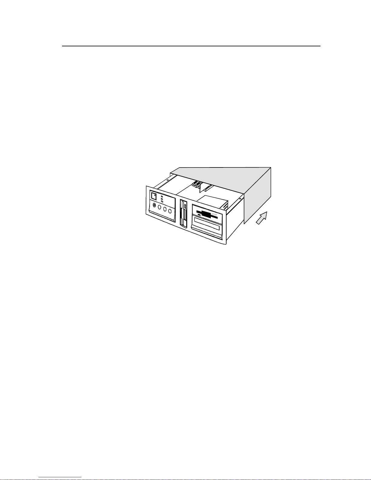
3. Remove the cover from your system as illustrated in
Figure 2-4.
If your computer differs from the one shown below, refer to
your computer’s manual for more details.
Figure 2-4: Removing the computer cover of your system.
Setting Up Your CD-ROM Drive 2-3
Page 19
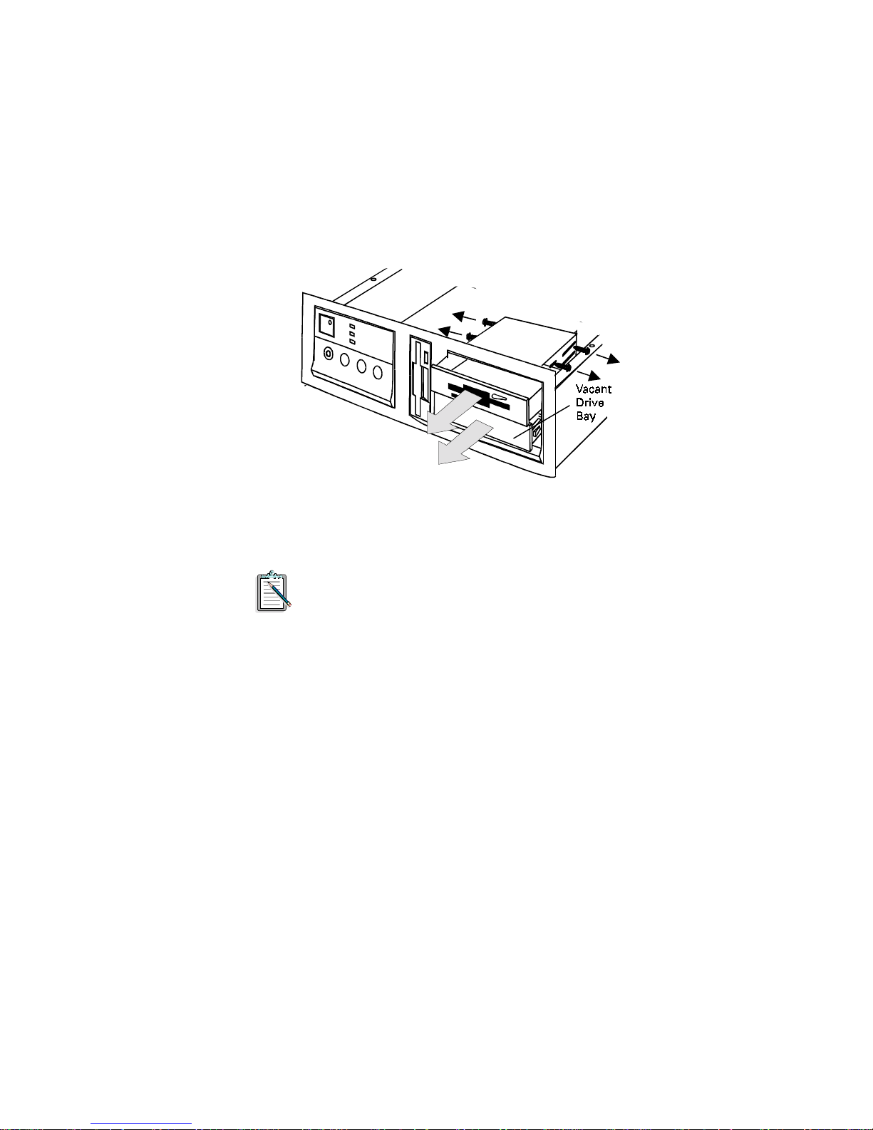
4. Locate a 5¼" drive bay for your CD-ROM drive.
5. Vacate a drive bay.
If a disk drive is positioned above your vacant drive bay, loosen
the screws of your disk drive and slide it out by two to three
inches. See Figure 2-5.
Figure 2-5: Vacating a dri ve bay.
For more information on how to vacate a drive bay , refer
to your computer system’s manual for assistance. If
you require further help, please consult a technician.
Setting Up Your CD-ROM Drive 2-4
Page 20
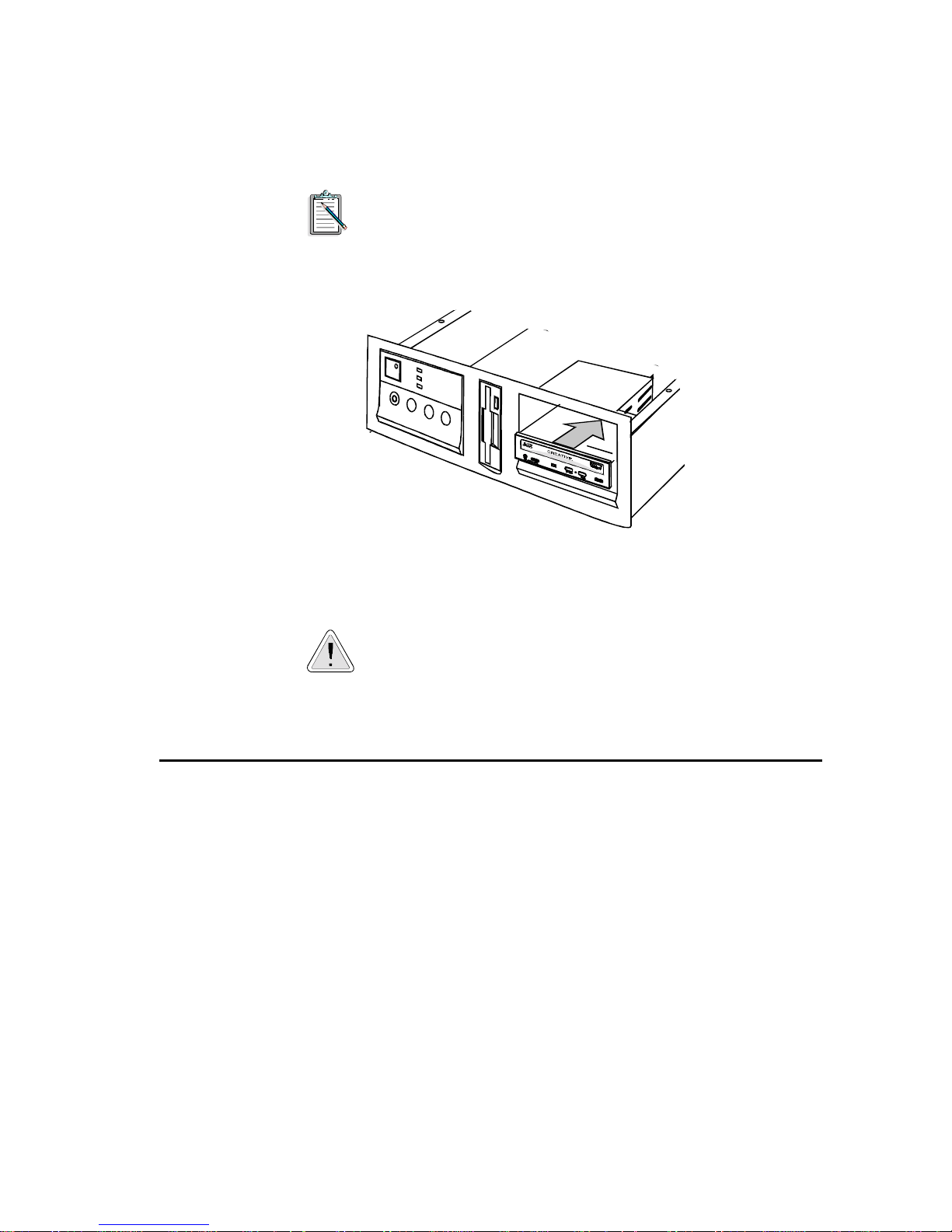
6. Insert your CD-ROM driv e into the v acant drive b ay as sho wn
in Figure 2-6.
Do not slide the drive completely into the vacant drive
bay . Leave some space at the rear so that it is easier for
you to connect cables to your drive.
Figure 2-6: Inserting your CD-ROM drive.
You may need to use some force to insert your
CD-ROM drive into your drive bay. However, please
refrain from excessive force as this may damage your
drive or other devices on your system.
Connecting Cables to Your Drive’s Rear Panel
T o connect all the necessar y cables to the rear panel of your CD-ROM
drive:
1. Locate an unused power cable from your system.
A power cable can be lo cated from your system’ s power supply
unit. The power supply unit is located at the right hand corner
on most systems.
Setting Up Your CD-ROM Drive 2-5
Page 21
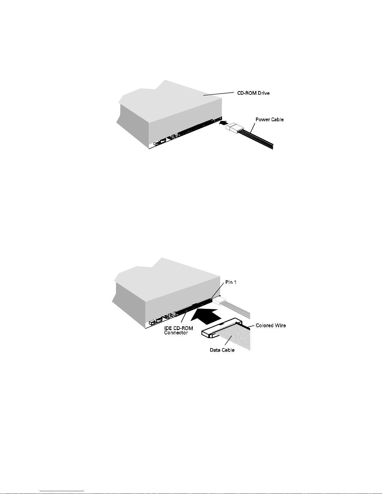
2. Connect the power cable to the CD-ROM drive as shown in
Figure 2-7.
Figure 2-7: Connecting po we r cable to your CD-ROM drive.
3. Connect the data cable to the CD-ROM drive as shown in
Figure 2-8. Make sure you align the col ored wire on the cable
to Pin 1 of the IDE CD-ROM Data Connector.
If you are connecting your drive to your hard disk controller
card, make sure that you use the data cable pro vided with your
package to connect your drive (see Figure 2-1 on page 2-1).
Figure 2-8: Connecting data cabl e to your CD-ROM drive.
Setting Up Your CD-ROM Drive 2-6
Page 22

4. If you are connecting your drive to an audio card, connect the
CD audio cable to the CD-ROM drive as shown in Figure 2-9.
Figure 2-9: Connecting CD audi o cable to your CD-ROM dri ve .
Connecting Cables to Your Card
After connecting the cables to the CD-ROM’ s rear panel, you need to
connect these cables to your audio or IDE CD-ROM interface card.
If you have purchased the drive in a multimedia upgrade kit, read
“Connecting Cables to Your Audio Card” in this section.
If you have purchased your drive with the IDE CD-ROM interface
card, read “Connecting C ables to Your IDE CD-ROM Interface Card”
in this section.
If you have purchased the drive as a stand-alone product, read
“Connecting Cables to Your Audio Card” to connect the drive to an
audio card or “Connecting Cables to Your IDE CD-ROM Interface
Card” to connect the drive to an IDE CD-ROM interface card.
If you are connecting your drive to your hard disk controller
card, read “Connecting Cables to Your Hard Disk Controller
Card” in this section.
Setting Up Your CD-ROM Drive 2-7
Page 23

Connecting Cables to Your Audio Card
T o connect the CD audio and data cables to your audio card (wh ich has
an IDE CD-ROM interface):
1. Connect the data cable to your audio card as shown in
Figure 2-10. Make su re you align the colored wi re on the cable
to Pin 1 of the IDE CD-ROM Data Connector.
If your audio card has multiple CD-ROM data
connectors, connect the data cable to the IDE CD-ROM
Data Connector.
Figure 2-10: Connecting dat a cable to the audio card.
2. Connect the CD audio cable to your audio card as shown in
Figure 2-11.
Figure 2-11: Connecting CD audio cable to the audio card.
Setting Up Your CD-ROM Drive 2-8
Page 24

3. Slide the drives back into place and fasten them to you r system
as shown in Figure 2-12.
Figure 2-12: Fastening the drives to your system.
4. Switch on your system.
5. Proceed to the section “Installing the Software” in this chapter.
Connecting Cables to Your IDE CD-ROM Interface Card
If your drive comes with an IDE CD-ROM inter face card, you need to
install the interface card and connect it to your drive.
Setting Up Your CD-ROM Drive 2-9
Page 25

To install the interface card:
1. Locate a vacant 16-bit slot in your system (see Figure 2-13).
Figure 2-13: Locating a vacant slot.
2. Remove the metal plate fro m the sl ot you hav e chosen an d put
the screw aside (see Figure 2-14).
Figure 2-14: Removing the metal pl ate from the slot.
Setting Up Your CD-ROM Drive 2-10
Page 26

3. Align the IDE CD-ROM interface card’s gold-stripped
connector with the expansion slot and gently lower it into the
slot (see Figure 2-15).
Figure 2-15: Inserting the IDE CD-ROM inte rfa ce card.
4. Secure the interface card to the expansion slot with the screw
you removed from the metal plate (see Figure 2-16).
Figure 2-16: Fastening the IDE CD-ROM interface card to your system.
Setting Up Your CD-ROM Drive 2 -11
Page 27

To connect the drive to the interface card:
1. Connect the data cable to your IDE CD-ROM interface card as
shown in Figure 2-17. Make sure you align the colored wire on
the cable to Pin 1 of the IDE CD-ROM Data Connector.
Figure 2-17: Connecting the data cable to the interfac e c a rd.
2. If you have an audio card installed in your system, connect the
CD audio cable to the CD Audio Connector on the audio card
as shown in Figure 2-18.
Figure 2-18: Connecting t he C D a udi o cable to the audio card.
Setting Up Your CD-ROM Drive 2-12
Page 28

3. If you do not have an audio card installed in your system,
connect a headphone or powered speakers to the Stereo Phon e
Jack on your drive’s front panel. Set the volume controls of
your drive and power ed speakers to minimum bef ore powering
on (or resetting) the system. This is to prevent possible damage
to the headphone or speaker.
4. Slide the drives back into place and fasten them to you r system
as shown in Figure 2-19.
Figure 2-19: Fastening the drives to your system.
5. Switch on your system.
6. Proceed to the section “Installing the Software” in this chapter.
Connecting Cables to Your Hard Disk Controller Card
To connect the data cable to your hard disk and hard disk controller
card:
1. If you have not backed up your hard disk, please do so before
you proceed. For more information, refer to your DOS
documentation.
2. Connect the power and data cables t o your hard di sk as shown
in Figure 2-20. Make sure you align the colored wire on the
cable to Pin 1 of your Hard Disk Data Connector.
The default setting for your CD-ROM drive is Slave
drive. Make sure that your hard d isk is set as the Master
drive. For more information, refer to the documen tation
that comes with your hard disk.
Setting Up Your CD-ROM Drive 2-13
Page 29

Figure 2-20: Connecting data cab le to y our hard disk.
Setting Up Your CD-ROM Drive 2-14
Page 30

3. Connect the data cable to your hard disk controller card as
shown in Figure 2-21. Make sure you align the colored w ire on
the cable to Pin 1 of your Hard Disk Data Connector.
Your hard disk controller card may differ from the one
shown in Figure 2-21.
Figure 2-21: Connecting data cable to the hard disk controller card.
Setting Up Your CD-ROM Drive 2-15
Page 31

4. If you have an audio card installed in your system, connect the
audio cable to the CD Audio Connector on the audio card as
shown in CD Figure 2-22.
Figure 2-22: Connecting t he C D a udi o cable to the audio card.
5. If you do not have an audio card installed in your system,
connect a headphone or powered sp eakers to the Stereo Phone
Jack on your drive’s front panel. Set the volume controls of
your drive and power ed speakers to minimum bef ore powering
on (or resetting) the system. This is to prevent possible damage
to the headphone or speaker.
Setting Up Your CD-ROM Drive 2-16
Page 32

6. Slide the drives back into place and fasten them to you r system
as shown in Figure 2-23.
Figure 2-23: Fastening the drives to your system.
7. Switch on your system.
8. Proceed to install the software.
Installing the Software
The following instructions show you how to install two drivers
required to contro l your CD-ROM drive and an application that all ows
you to pla y audio CDs.
To install the software:
1. Insert the CD-ROM Installation Disk into drive A or B of your
computer.
2. Type
3. Follow the instructions on the screen to complete the
A:INSTALL
installation.
If you are connecting your drive to the hard disk
controller card, select 1F0 for the I/O address.
B:INSTALL
(or
) and press <Enter>.
Setting Up Your CD-ROM Drive 2-17
Page 33

The installation program creates a directory to store the acco mpanying
software. The program adds the following statements to your
AUTOEXEC.BAT and CONFIG.SYS files respectively:
AUTOEXEC.BAT:
C:\path\MSCDEX /D:MSCD001 /M:8 /V
CONFIG.SYS:
DEVICE=C:\path\SBIDE.SYS /D:MSCD001 /P:1E8,11 /V
If you are connecting your drive to the hard disk controller
card, the statement added to your CONFIG.SYS is
DEVICE=C:\path\SBIDE.SYS /D:MSCD001 /P:1F0,14 /V
For more information on these two statements, refer to the section
“Changing the Driver Settings” in Chapter 4. It is important to reboot
your system for the changes to take effect. When you reboot, the
MSCDEX statement will display the drive letter assigned to your
CD-ROM drive.
If you wish to connect your new drive to your existing
CD-ROM drive, read the section “Connecting Additional
Drives” in Chapter 4. If you wish to replace your current
CD-ROM drive with this new drive, remove your drive’s driver
settings from the CONFIG.SYS file before you reboot your
system. Refer to your DOS manual for more information.
T esting the Installation
After installing the software and rebooting your system, you need to
ensure that your CD-ROM drive and drivers are installed properly.
Before you test your drive, make sure a pair o f speakers are connected
to your system. If you do not have an audio card, connect your
speakers to the Stereo Phone Jack on your drive’s front panel.
To test that your drive is working properly:
1. Load an audio CD onto your disc tray.
2. Change to the installed directory.
3. Type
4. Follow the instructions on the screen.
TESTCD
and press <Enter>.
Setting Up Your CD-ROM Drive 2-18
Page 34

TESTCD does the following:
❑
Checks that the drive is properly set up.
If you see a MSCDEX error message, check that SBIDE.SYS
is properly installed (see the section “Changing the Driver
Settings” in Chapter 4). Also, ensure that the data and power
cables are properly connected to the CD-ROM drive.
❑
Checks that there is audio output.
If there is no audio output, ref er to Appendix B.
If your CD-ROM drive and drivers are installed properly, you
can replace the cover of your system.
Setting Up Your CD-ROM Drive 2-19
Page 35

Using QuickCD
QuickCD allows you to play audio CDs in DOS and Windows. Like
your CD player, QuickCD is easy and fun to operate.
This chapter provides you with information on:
❑
Running DOS QuickCD
❑
Running Windows QuickCD
If you have not installed the software that comes with your
audio card, you should install it before proceeding.
Running DOS QuickCD
3
To run DOS QuickCD:
1. Change to your sound directory.
2. Change to PLAYCD subdirectory.
Using QuickCD 3-1
Page 36

3. At the DOS prompt, ty pe
QCD
and press <Enter>.
The QuickCD screen similar to Figure 3-1 appears.
Figure 3-1: The QuickCD screen.
If you have more than one drive, this program allows you to
specify the desired drive at the DOS prompt. For example, to
play the audio disc from your F drive, type
press <E nter>.
Understanding the DOS QuickCD Screen
DOS QuickCD supports the same features found on a CD player and
more. To help you use these features, the following are descriptions
of the different buttons and boxes (see Figure 3-1) found on the
QuickCD screen:
Eject button Ejects or closes the tray.
This function only applies if your
CD-ROM drive has a motorized tray
loading system.
Play button Plays the track shown in the Track box.
Stop button Stops the track.
QCD /D:F
and
Pause/Resume button Pauses or resumes the track.
Using QuickCD 3-2
Page 37

Next Track button Plays the next track.
If it is the end of the CD, the first track is
played.
Previous Track button Plays the previous track.
If it is the start of the CD, the last track is
played.
Fast Forward button Forwards the current track by 16 seconds.
If the end of th e last track is encountered,
this function is ignored.
Rewind button Rewinds the current track by 16 seconds.
If it is the start of the first track, this
function is ignored.
Next Drive button Changes to the next CD-ROM drive.
If there is only one drive, this function is
ignored.
Drive box Displays the current CD-ROM drive.
Mode box Displays the current operation.
T otal Time box Displays the total time required to play all
Volume Control slider Controls the volume of the CD audio.
Track box Displays the current track and duration of
Using the Keyboard and Mouse
You can control and select the various features (buttons and boxes)
found on the QuickCD screen by using the mouse or the keyboard.
Click on a button to start an operation.
Click the left or right mouse button to increase or decrease the
volume, after you have clicked on the Volume Control Slider.
tracks on the CD.
To increase or decrease the volume, use
the up or down arrow key.
the track.
Use the left and right arrow keys to choose a button.
Press <Enter> to start the operation.
Use the up or down arrow key to increase or decrease the
volume, after you have selected the Volume Control Slider.
Using QuickCD 3-3
Page 38

Quitting DOS QuickCD
To q uit DOS QuickCD, do one of the following:
❑
Press <Esc>.
❑
Click on the Title box.
Running W indows QuickCD
Before you can use Windows QuickCD, you need to
❑
Set it up in Windows
❑
Install the MCICDA.DRV d r iver that comes with your
Windows 3.1 package.
MCICDA.DRV is the device driver that allows you to play
audio CDs in Windows.
To set up QuickCD in Windows:
1. Click the Accessories group window.
2. Select New from the File menu.
The New Program Object dialog box s i milar to Figu re 3-2
appears.
Figure 3-2: The New Program Object dialog box.
Using QuickCD 3-4
Page 39

3. Select Program Item and choose OK.
The Program Item Properties dialog box similar to Figure 3-3
appears.
Figure 3-3: The Program Item Properties dialog box.
4. Type in the description as shown in Figure 3-3.
5. Choose OK.
The QuickCD icon appears in the Accessories group window.
To add MCICDA.DRV:
1. Double-click the Control Panel icon in the Main group
window.
The Control Panel group window similar to Figure 3-4
appears.
Figure 3-4: The Control Panel group window.
Using QuickCD 3-5
Page 40

2. Double-click the Drivers icon in the Control Panel group
window.
The Drivers dialog box similar to Figure 3-5 appears.
Figure 3-5: The Drivers dialog box.
3. Check that the statement [MCI] CD Audio appears in the
Installed Drivers list box.
❑
If the statement [MCI] CD Audio appears in the Drivers
dialog box, choose Close to exit the Drivers dialog box.
You can proceed to run Windows QuickCD.
❑
If the statement [MCI] CD Audio does not appear in the
Drivers dialog box, follow steps 4, 5, 6, and 7 to add this
statement.
4. Choose Add... from the Drivers dialog box.
The Add dialog box similar to Figure 3-6 appears.
Figure 3-6: The Add dialog box.
5. Select [MCI] CD Audio from the Add dialog box.
Using QuickCD 3-6
Page 41

6. Choose OK.
7. Restart Windows for the changes to take effect.
Starting W indows QuickCD
After you set up Windows QuickCD, you can run the program from
your Accessories group window.
To run Windows QuickCD:
1. Double-click the Qui ckCD icon in yo ur Access ories gro up
window.
The QuickCD control window similar to Figure 3-7
appears.
Understanding the Windows QuickCD Cont rol W indow
The following describes the bu ttons, sli ders, and dis play box found on
the QuickCD control window:
Off switch Quits QuickCD.
Eject button Ejects or closes the tray.
Figure 3-7: The QuickCD control window.
This function only applies if your
CD-ROM drive has a motorized tray
loading system.
Using QuickCD 3-7
Page 42

Play button Plays the track shown in the Display box.
Stop button Stops the track.
Pause button Pauses or resumes the track.
Previous Track button Plays the previous track.
If it is the start of the CD, the last track is
played.
Rewind button Rewinds the current track by 10 seconds.
If it is the start of the first track, this
function is ignored.
Fast Forward button Forwards the current track by 10 second s.
If the end of the last track is encountered,
this function is ignored.
Next Track button Plays the next track.
If it is the end of the CD, the first track is
played.
Mixer button Activates the Mixer.
Slider thumb Rewinds or forwards the current track.
Track Selection button Allows you to select the desired track.
Display box Displays the current track and duration of
Control Menu box Activates the Control menu.
Using the Keyboard and Mouse
You can control and select the various features (buttons and sliders)
found on the QuickCD control window by using the mouse or the
keyboard.
Click on the Track Selection button to play a desired track.
Click on a button to select and start an operation.
Drag the Slider thumb to forward or rewind the current track.
If there are more than 20 tracks, choose
to display the rest of the tracks.
the track.
Using QuickCD 3-8
Page 43

Press <Tab> to choose a button.
Press <Enter> to start the selected operation.
Move the Slider thumb with the left or right arrow key to
forward or rewind the current track.
Using the Control Menu Box
The Control Menu Box (top left corner of the control window)
contains commands that allow y ou to perfor m various ope rations such
as move, restore, and close the QuickCD control window.
To activate the Control menu:
1. Click on the Control Menu box.
The Control menu similar to Figure 3-8 appears.
The following des cribes the commands found on the menu:
Restore Restores the QuickCD w indow fr om its icon.
Move Allows you to move QuickCD around the
Minimize Reduces QuickCD to an icon.
Close Quits QuickCD.
Switch T o Opens the Task List dialog box which allow s
Figure 3-8: The Control menu.
desktop.
you to select another running application.
Using QuickCD 3-9
Page 44

Play Plays the current track.
Stop Stops the track.
Pause Pauses or resumes the track.
Skip Selects the next track and plays it.
If it is the end of the CD, the first track is
played.
Always on Top Displays QuickCD on top of the active
window.
Preferences Allows you to customize QuickCD.
About QuickCD Displays copyright information about
QuickCD.
Customizing W indows QuickCD
You can customize Windows QuickCD to work in the way you like.
You may wish to automatically play a CD wh en it is inserted or stop
playing every time you exit the application.
To customize Windows QuickCD:
1. Select Preferences from the Control menu.
The Preferences dialog box similar to Figure 3-9 appears.
Figure 3-9: The Preferences dialog bo x.
2. Select t he desired o pt ions.
❑
Automatically play when CD is inserted
Plays an audio CD automatically if it is loaded in the disk
tray when you start QuickCD.
❑
Continuous playback
Repeats from track 1 after the final track is played.
Using QuickCD 3-10
Page 45

❑
Minimize on play
Minimizes QuickCD to an icon when playing audio CD.
❑
Stop playback on exit
Stops an audio CD when you exit QuickCD.
3. Choose OK.
Quitting W indows QuickCD
To quit Windows QuickCD, do one of the following:
❑
Choose the On/Off button.
❑
Select Close from the Control menu.
❑
Press <Alt+F4>.
Using QuickCD 3-11
Page 46

4
Doing More with Your CD-ROM Drive
This chapter comprises several sections to help you get more out of
your CD-ROM drive. The chapter is organized as follows:
❑
Changing the Driver Settings
This section describes the parameters of the drivers that control
your CD-ROM drive and the available settings of each driver.
❑
Running CDSETUP
This section shows you how to run a utility to change your IDE
port and IRQ line settings.
❑
Locking the Disc Tray
You can lock your disc tr ay if you wish. Th is section descr ibes
two DOS utilities for locking and unlocking the disc tray.
❑
Connecting Additional Drive
This section shows you how to connect an additional drive to
your CD-ROM drive.
Changing the Driver Settings
This section shows you how to change the settings of the two drivers
that control your CD-ROM drive.
The two drivers mentioned above are:
❑
SBIDE.SYS
The hardware-dependent driver for your CD-ROM drive.
It enables your CD-ROM drive to communicate effectively
with your PC.
❑
MSCDEX.EXE
The Microsoft CD-ROM Extensions program — the
software-dependent driver for your drive. It is a standard
Doing More with Your CD-ROM Drive 4-1
Page 47

mechanism created by Microsoft to read lar ge files, and it gives
your PC the capability to communicate with your CD-ROM
drive.
The presence of these two drivers are reflected by the following
statements in the CONFIG.SYS and AUTOEXEC.BAT files after you
run the installation program.
CONFIG.SYS:
DEVICE=C: \ path\SBIDE.SYS /D:MSCD001 /P:1E8,11 /V
AUTOEXEC.BAT:
C:\path\MSCDEX /D:MSCD001 /M:8 /V
To help you to edit these parameters correctly, the following sections
list the syntax for the SBIDE.SYS and MSCDEX.EXE statements. It
also explains the different parameters you can set in each driver.
This section ass umes t hat you kn ow DOS . You should at least
be comfortable in changing statements in your
AUTOEXEC.BAT an d CONFIG.SYS. If you do not know
DOS, please ask someone who does to help you.
SBIDE.SYS Settings
SBIDE.SYS supports Primary, Secondary, Tertiary, and Quaternary
ports. These ports are industrial conventions for the combination of
I/O addresses and IRQ line used by an IDE interface.
The syntax of the SBIDE.SYS statement in CONFIG.SYS is:
DEVICE=C: \ path\SBIDE.SYS /D:device /P:addr,irq /V
Doing More with Your CD-ROM Drive 4-2
Page 48

The descriptions of the parameters are as follows:
Parameter Description
path
/D:device
:addr,irq
/P
Specifies the directory where the driver is stored.
Specifies the name of the CD- ROM drive. This must be
identical to the device name specified by the MSCDEX
statement in the AUTOEXEC.BAT file. The
installation default setting is MSCD001.
Specifies the base I/O address (
and IRQ l ine (
your card.
irq
) for the IDE CD-ROM interface on
addr
can be 1F0, 170, 1E8 (default) , or 1 68.
addr
) in hexadecimal
irq can be 10, 1 1 (d efault), 12, 14 , or 15. See Table 4-1.
Table 4-1 :Standard settings for IDE ports.
IDE Port addr, i rq I/O Addresses Used
Primary 1F0, 14
Secondary 170, 15
1F0H to 1F7H,
3F6H to 3F7H
170H to 177H,
376H to 377H
/V
Tertiary 1E8, 11 or 12 1E8H to 1EFH
Quaternary 168, 10 or 11 168H to 16FH
Select the Primary Port only if you connect your
drive to the primary hard disk controller card.
Also, you can only connect two IDE devices to
each IDE port in a system and the names of these
IDE ports do not indicate any kind of sequence
for adding IDE devices.
Displays the drive t ype, firmware version , port address,
and interrupt of your drive.
Y ou can also ru n CDSETUP to change the base I/O address and
IRQ line of your card. Refer to the section “Running
CDSETUP” in this chapter for more information.
Doing More with Your CD-ROM Drive 4-3
Page 49

MSCDEX.EXE Settings
The syntax of the MSCDEX.EXE statement in AUTOEXEC.BAT is:
C:\path\MSCDEX /D:device /M:xx [/L:drive] [/E] /V
[ ] in the above statement refers to any optional parameters.
After making changes to the statement, please remember to
reboot your system for the changes to take effect.
The descriptions of the parameters are as follows:
Parameter Description
path
/D:
/M:
/L:
device
xx
drive
Specifies the directory where the driver is stored.
Specifies the name of the CD-ROM drive.
Installation default is MSCD001.
Specifies the number of buf fers to use for temporary
storage of the most recent data. xx ranges from 2 to
32.
The performance of your drive increases with the
value of xx.
As each buffer uses about 2 KB of memory,
specifying too many buffers may interfere
with programs that have large memory
requirements.
Specifies the drive letter assigned to the first
CD-ROM drive. If this is not specified, the next
available drive letter is used by your system.
If you have specified the LASTDRIVE
statement in your CONFIG.SYS, make sure
that the drive letter falls within the specified
range. See Appendix C, “Troubleshooting”
for more information.
/E
/V
Specifies the use of expanded memory. This
parameter is only applicable to Expanded Memory
Manager LIM version 3.2 or later.
Displays RAM allocation and expanded memor y
usage at boot time.
Doing More with Your CD-ROM Drive 4-4
Page 50

Running CDSETUP
After you have installed your software, you can run CDSETUP to
change the base I/O address and IRQ line of your IDE interface.
To change the base I/O address and IRQ line of your card, y ou
need to change the jumper setting on your audio or IDE
CD-ROM interface card. Refer to the appendix “Resolving
Hardware Conflicts” to change the jumper setting on your IDE
CD-ROM interface card. To change the jumper se tting on your
audio card, refer to the documentation that comes with your
audio card.
To run CDSETUP:
1. Change to your installed directory.
2. Type
3. Follow the instructions on the screen.
4. Restart your system for the changes to take effect.
CDSETUP
If you do not wish to run CDSETUP, you can use a text editor
to change the base I/O address and IRQ line of your card . Refer
to the section “Changing the Driver Settings” in this chapter for
more information.
Locking the Disc Tr ay
If you do not want others to remove your CD from the disc tray, you
can lock or unlock the disc tray using the DOS utilities
LOCKCD.EXE and UNLOCKCD.EXE. LOCKCD.EXE and
UNLOCKCD.EXE allow you to disable and enable the Stop/Eject
button respectively.
and press <Enter>.
To lock the disc tray:
1. Change to the installed directory.
2. Type
LOCKCD
d1: [d2: d3: d4:] and press <Enter>.
Doing More with Your CD-ROM Drive 4-5
Page 51

d1, d2, d3
, and d4 refer to the drives you want to lock. For
example, to lock the disc trays for drives D, E, and F, type
LOCKCD D: E: F:
and press <Enter>.
Once you have locked the tray, it can only be ejected if you run
UNLOCKCD.EXE or restart the system.
To unlock the disc tray:
1. Change to the installed directory.
2. Type
d1, d2, d3
UNLOCKCD
, and d4 refer to the drives you want to unlock.
d1: [d2: d3: d4:
Connecting Additional Drives
You can connect additional drives to your system. You can connect
two CD-ROM drives to each IDE port. When you connect the driv es,
you need to assign the drive as the Master or Slave d rive. This is done
by configuring the Master/Slave Jumper settings at the back of the
drive.
Do not connect two CD-ROM drives to the same IDE port if
they require different device drivers. The device drivers may
not work together.
This section shows you how to:
] and press <Enter>.
❑
Enable and Disable Jumpers
❑
Configure the Master/Slave Jumper Settings
❑
Connect Additional Drive to Your Drive
You need a data cable (similar to the one that comes with your
package) to connect the drives.
Doing More with Your CD-ROM Drive 4-6
Page 52

Enabling and Disabling Jumpers
A jumper exists in two states: enabled or disabled. A jumper is
enabled when a plastic hood called a jumper block is placed over the
jumper’s two pins as shown in Figure 4-1.
Figure 4-1: An enabled ju m pe r.
In contrast, a disabled jumper is one in which the jumper block is not
placed over the jumper’s two pins as shown in Figure 4-2.
Figure 4-2: Disabled jumpers.
Configuring the Master/Slave Jumper Setting
You can set your drive as the Master or Slave drive using the
Master/Slave Jumper at the back of the drive. The factory default is
Slave.
The instructions below show you how to connect an additional
GCD-R542B to your drive. If your additional drive is not
GCD-R542B, refer to the documentation that comes with your drive.
To configure your drive to Master or Slave:
1. Remove the jumper blocks from the Master/Slave Jumper of
your drive.
Doing More with Your CD-ROM Drive 4-7
Page 53

2. Set your drive by placing the jumper blocks on the desired
jumper as shown in Figure 4-3.
Figure 4-3: The available ID Jumper settings.
The jumper labeled CS is reserved and should not be used.
Doing More with Your CD-ROM Drive 4-8
Page 54

Connecting the Drives
After you have set your drive as the Master or Slave drive, you can
connect it to your existing drive using a daisy-chain cable as sh own in
Figure 4-4.
Make sure that you align the colored wire on the data cable to
Pin 1 on your CD -ROM drives’ IDE CD-ROM Connect or , and
the CD audio cable to the Master drive.
Figure 4-4: Daisy-chaining the drives.
Doing More with Your CD-ROM Drive 4-9
Page 55

Technical Data
This appendix provides you with the technical specifications of your
drive.
Physical Dimensions
Height 41.5 mm
Width 146.0 mm
Depth 189.0 mm
Color PC white
A
Performance Characteristics
Buffer Memory 256 KB
Data Transfer Rate
Single Speed 150 KB/sec
Quad Speed 600 KB/sec
Access Time
1/3 Stroke 220 msec (Typical)
MTBF (Mean Time between failure) 50,000 POH (10% duty)
Error Rate
Normal Speed < 10
Quad Speed < 10
< 10
< 10
-15
(Mode 1)
-12
(Mode 2)
-15
(Mode 1)
-12
(Mode 2)
Technical Data A-1
Page 56

Power Supply 5 Volts ± 5%
Current Drain 0.35 Amp (Max.) ± 5 Volts
T ypical Audio Performance
Frequency Response 20 Hz to 20 kHz ± 3 dB
Signal to Noise Ratio 85 dB
Total Harm onic Distortion (at 1 kHz) 0.2% (Typical)
Channel Separation 70 dB
12 Volts ± 10%
0.8 Amp (Max.) ± 12 Volts
Line Output 0.8 V
Headphone Output 0.7 V
Environmental Operating Limits
Ambient Temperature (No Condensation)
Operating 0 to 40°C
Storage 20 to 60
Relative Humidity (No Condensation)
Operating 10 to 60%
Storage 10 to 80%
(RL:47kΩ ) (Typical)
rms
(RL:100kΩ ) (Typical)
rms
°
C
Technical Data A-2
Page 57

Resolving Hardware Conflicts
This appendix provides you with information on the hardware settings
of the IDE CD-ROM interface card. It shows you how to change the
Base I/O address and IRQ line if conflicts occur between the IDE
CD-ROM interface card and other devices.
To resolve hardware conflicts between your audio card and
other devices, read the documentation that comes with your
audio card.
I/O Addresses
The interface card’s I/O addresses are the addresses used by your
computer’s microp rocessor to distinguish the IDE CD-ROM interface
card from other peripheral devices in your system when sending or
receiving data. The base I/O addresses and their I/O address ranges
are tabulated below.
B
Table B-1: I/O add resses fo r IDE por t.
IDE Port Base I/O Address I/O Address Range
Secondary 170H 170H to 177H, 376H to 377H
Tertiary 1E8H (Default) 1E8H to 1EFH
Quaternary 168H 168H to 16FH
Resolving Hardware Conflicts B-1
Page 58

Changing Base I/O Address
If I/O address conflicts occur between the IDE CD-ROM interface
card and other devices, you need to change the base I/O address of the
IDE CD-ROM interface card or that of the conflicting device.
Change the default base I/O address of the IDE CD-ROM
interface card only when another device absolutely requires the
I/O addresses assigned to the interface card. If you change the
I/O address of your card, you may also need to change the IRQ
line. Refer to the section “Changing IRQ Line”.
To change the interface card’s base I/O address:
1. Switch off your system and all peripheral devices.
2. Remove your system’ s cov er and IDE CD-ROM interface card.
Resolving Hardware Conflicts B-2
Page 59

3. Place the jumper block on the interface card to select the
desired base I/O address as shown in Figure B-1 . A jumper
block is a removable plastic hood that fits over a pair of pins.
4. Run CDSETUP or the installation program to update the
setting in your CONFIG.SYS file’s SBIDE.SYS statement.
For more information on CDSETUP, refer to the section
“Running CDSETUP” in Chapter 4.
5. Reboot the system for changes to take effect.
Figure B-1: IDE Port settings for the IDE CD-ROM Interface.
Resolving Hardware Conflicts B-3
Page 60

Changing IRQ Line
Four IRQ Lines are available for your IDE CD-ROM interface card:
10, 11 ( fact ory defau lt s et ting), 12 and 15. Refer to Table B-2 for the
standard IRQ line assigned to the different IDE port.
Table B-2: IRQ Lin es for the re specti ve IDE Port.
IDE Port IRQ Lines
Secondary 15
T ertiary (Default) 11 (Default) or 12
Quarternary 10 or 11
Refer to the section “Changing Base I/O Address” in this
chapter to identify the IDE Port you have specified.
Resolving Hardware Conflicts B-4
Page 61

To change the IRQ line, enable the jumpers corresponding to the
settings shown in Figure B-2 .
Figure B-2: The available IRQ settings of your ID E CD -R O M
To ensure that your changes to the IDE CD-ROM interface
settings are effected, make corresponding changes to the
hardware device driver settings. Refer to the section
“Changing the Driver Settings” in Chapter 4 for more
information.
Interface.
Resolving Hardware Conflicts B-5
Page 62

T roubleshooting
This appendix helps you troubleshoot some common problems you
might face.
Problems with CD-ROM Drive
C
Problem
Causes
Solutions
No sound from speakers.
1. Audio cable is n ot connected pro perly or the vol ume
is not adjusted to an audible level.
2. The drive might be faulty.
3. The card might be faulty.
1. Check that your speakers are connected to the
correct jack on the sound card and the volume is set
to mid-range. Check the Mixer to ensure that the
volume is set to mid-range. (See the documentation
that comes with your audio card for more details.)
2. Connect earphones to the Stereo Phone Jack. If
there is no sound from y our earphones, con sult your
dealer about your faulty drive.
3. Connect earphones to the stereo phone jack. If there
is sound from your earphones, check to see the audio
cable is connected from the drive to the audio card
(see the section “Installing Your Drive” in
Chapter 2). If the audio cable is connected and there
is no sound from your speakers, consu lt your dealer
about your faulty card.
Troubleshooting C-1
Page 63

Problem
Interface card or CD-ROM drive is not ready.
Causes
Solutions
1. The power or data cable is not connected.
2. MSCDEX.EXE or SBIDE.SYS is not loaded.
3. Some BIOS that include power management
features use IRQ 12 or 15.
1. Ensure the power and CD audio cables are
connected properly to the drive (see the section
“Installing Your Drive” in Chapter 2).
2. Your CD-ROM drive requires MSCDEX.EXE and
SBIDE.SYS to access the drive. Check your
AUTOEXEC.BAT file for the statement
C:\path\MSCDEX.EXE /D:MSCD001 /M:8 /V
and CONFIG.SYS file for the statement
DEVICE=C:\path\SBIDE.SYS /D:MSCD001
/P:1E8,11 /V
(see the section “Changing the
Driver Settings” in Chapter 4 for more information).
If you have connected the drive to the hard disk
controller card, the statement added to your
CONFIG.SYS file is
DEVICE=C:\path\SBIDE.SYS /D:MSCD001
/P:1F0,14 /V
3. Change the IRQ setting of the audio or IDE
CD-ROM interface card. Refer to the
documentation for more information.
Problem
Cause
Not enough drive letters available.
You have installed more than 3 logical or physical
drives in your system.
Solution
Modify the LASTDRIVE statement in your CONFIG.SYS
file to reflect the maximum number of drives you can access. For
example, if you have installed 5 drives in your system, your current
LASTDRIVE statement in your CONFIG.SYS file will be
LASTDRIVE=E. Change this statement to LASTDRIVE=F if you
want to install an additional drive to your system. See your DOS
manual for more details.
Troubleshooting C-2
Page 64

Problem
I do not know how to specify the settings for the
MSCDEX driver when I have two or more CD-ROM
drives using dif ferent device dri vers in my system. For
example, I have a Creative IDE and another CD-ROM
drive connected to my system.
Solution
Modify the MSCDEX statement in your
AUTOEXEC.BAT file to include a second device name
e.g., MSCD002 (see the following statement).
[path]MSCDEX /D:MSCD001 /D:MSCD002 /V /M:8
This statement defines the MSCDEX driver for two
CD-ROM drives with device names MSCD001 and
MSCD002. These device names have to be identical to
the device names for the respective CD-ROM device
drivers in the CONFIG.SYS file as shown below.
DEVICE= [path]SBIDE.SYS /D:MSCD001
/P:1E8,11 /V
DEVICE= [path]xxx.SYS /D:MSCD002
SBIDE.SYS is the device driver for Creative
IDE CD-ROM drive and
xxx
.SYS is the device
driver for the other CD-ROM drive.
Troubleshooting C-3
Page 65

Glossary
CD-ROM/XA CD-ROM Extended Architecture. An
DAT Digital Audio Tape. A magnetic tape
Quad Velocity Transfer Also known as Quad Speed Tr ansfer.
D
extended CD-ROM format developed by
Philips, Sony, and Microsoft that allows
computer data, compressed audio data,
and video/picture data to share a single
track.
storage medium for the digital recording
and playback of encoded audio
information.
The transfer of data from the CD-ROM
drive to the microprocessor at 600 KB per
second compared to the normal rate of
150 KB per second.
Base I/O Address The address from which the interface
card’s I/O addresses begin.
I/O Addresses The input/output addresses used by your
computer’s micropro cessor to distinguish
your CD-ROM drive from other
peripherals in your sys tem when sendin g
or receiving data.
Kodak’s Photo CD A disc format and a specialized player
developed and marketed by Kodak.
Multimedia Applications that have been enhanced by
the addition of sound, animation, or
video. It could also be a combination of
all these.
Glossary D-1
Page 66

Track A logical region of a disc. Each track can
contain sound, animation , video, or other
computer data.
Glossary D-2
Page 67

Technical Support
We are committed to giving you the best product as well as the best
technical support. When you contact us, please have the following
information:
❑
Hardware configuration information such as the base I/O
address, IRQ, or DMA channel used.
❑
Error message on the screen and how it came about.
❑
Information on the adapter card that conflicts with your card.
This section shows where you can contact us:
❑
Inside U.S.A., Canada and South America
❑
Inside Europe
❑
Inside Asia
E
❑
Through Compuserve
Inside U.S.A., Canada and South America
CREATIVE LABS, INC.
1523 Cimarron Plaza
Stillwater
OK 74075
U.S.A.
Tel : +405 742 6622
Fax : +405 742 6633
BBS : +405 742 6660
Operating Hours (U.S.A. Central Time)
Mon-Sun : 8:00 am-12:00 am (16 hours)
Public Holidays : Closed
Technical Support
Technical Support E-1
Page 68

Inside Europe
CREATIVE LABS (IRELAND) LTD.
Ballycoolin Business Park
Blanchardstown
Dublin 15
Ireland
Ireland
Tel : +353 1 820 7555
Fax : +353 1 820 5052
BBS : +353 1 820 3784 (hst)
: +353 1 820 3818 (Zyxel)
France
Tel : +33 1 39 20 04 21
Fax : +33 1 39 20 90 10
BBS : +33 1 39 20 90 43 (hst)
: +33 1 39 20 90 47 (v32bis)
Minitel: 3615 CREATIVE and
3617 CREATIVE
UK
Tel : +44 01734 344 744
Fax : +44 01734 320 271
BBS : +44 01743 360 287
Technical Support
Belgium
(for Benelux)
Germany
(for Central and
Eastern Europe)
Scandinavia
Tel : +32 03 281 35 70
Fax : +32 03 281 35 80
Tel : +49 089 9579081
Fax : +49 089 9577453
BBS : +49 089 9557274
Tel : +45 4824 4322
Fax : +45 4824 4323
Spain
Tel : 900 953536 (Freephone)
Operating Hours
Mon-Fri : Business Hours
Sat-Sun : Closed
Technical Support E-2
Page 69

FaxBack is a facility that allows you to obtain product and
technical information through facsimile services. In Europe, use
the following number: +353 1 820 3667
Inside Asia
Throughout the rest of Europe, please direct all faxes to
Ireland.
CREATIVE TECHNOLOGY LTD.
Blk 75, #01-04
Ayer Rajah Crescent
Singapore 0513
Tel : +65 773 4048
Fax : +65 773 0353
BBS : +65 776 2423
Operating Hours (Singapore Time)
Mon-Fri : 9:00 am-6:00 pm
Sat : 9:00 am-1:00 pm
Sun & Publi c Holidays : Close d
Through Compuserve
To serve you better, we have created a Creative Labs Forum on
Compuserve. Through this forum:
Technical Support
❑
You will have direct access to our company representatives
who will be there to answer your questions.
❑
You will be part of an interactive community of Creative’s
product users. Here you can share experiences and ideas and
also seek solutions to problems.
❑
We will also keep you up-to-date on the latest product
information, soft ware updat es, and fixes to common p roblems.
❑
We will also welcome your recommendations and suggestions
for new products and for improving our products in future
releases.
Technical Support E-3
Page 70

If you are already a member of Compuserve
All you need to do to access the forum is:
❑
At the Compuserve prompt,
Go Blaster
Type
and press <Enter>.
If you are not a member of Compuserve
(valid only in U.S.A.)
We have arranged for you to receive a free introductory Compuserve
membership which includes:
❑
one free month of Compuserve’s Basic Services,
❑
a $15 introductory usage credit to explore the Creative Forum
and Compuserve’s other Extended Services,
❑
a private User ID Number and Password, and
❑
a complimentary copy of CompuServe Magazine,
Compuserve’s monthly computing publication.
To receive this special offer:
❑
Call 1-800-524-3388 and
Ask for Representative #228.
Technical Support E-4
 Loading...