

Page 1
Page 2

User Manual
Creative Network Blaster
Wireless LAN USB Adapter 2030
Information in this document is subject to change without notice and does not represent a commitment on the part of Creative Technology Ltd. No part of this manual may be
reproduced or transmitted in any form or by any means, electronic or mechanical, including photocopying and recording, for any purpose without the written permission of
Creative Technology Ltd. The software described in this document is furnished under a license agreement and may be used or copied only in accordance with the terms of the
license agreement. It is against the law to copy the software on any other medium except as specifically allowed in the license agreement. The licensee may make one copy of
the software for backup purposes.
Copyright © 2002 by Creative Technology Ltd. All rights reserved.
Version 1.1
May 2002
Network Blaster is a registered trademark of Creative Technology Ltd.
Broadxent Pte Ltd is a subsidiary of Creative Technology Ltd.
IBM is a registered trademark of International Business Machines Corporation.
Intel and Pentium are registered trademarks of Intel Corporation.
Microsoft, MS-DOS, Windows, and the Windows logo are registered trademarks of Microsoft Corporation.
All other products are trademarks or registered trademarks of their respective owners. All rights reserved.
Page 3

Contents
Safety Precautions
General Safety.........................................................................................vii
FCC Radiation Exposure Statement ...........................................................viii
Introduction
Before You Begin ..................................................................................... xi
Package Contents ........................................................................... xi
Recording Model and Serial Numbers ................................................ xi
Minimum System Requirements ....................................................... xi
Document Conventions.............................................................................xii
1 About Wireless LAN
Wireless LAN ......................................................................................... 1-1
Installation................................................................................... 1-1
Cost ............................................................................................ 1-1
Speed.......................................................................................... 1-1
Mobility ....................................................................................... 1-1
Scalability .................................................................................... 1-1
Ad-hoc mode ........................................................................ 1-2
Infrastructure mode............................................................... 1-2
Flexibility ..................................................................................... 1-2
2 Installing Hardware
About Rear View of Wireless LAN USB Adapter .......................................... 2-1
-iii
Page 4

3 Installing and Uninstalling Drivers and
Configuration Utility
Installing Drivers and Configuration Utility ................................................3-2
In Windows 98SE.......................................................................... 3-2
In Windows 2000.......................................................................... 3-8
In Windows Me........................................................................... 3-14
In Windows XP ........................................................................... 3-19
Uninstalling Drivers and Configuration Utility ........................................... 3-25
4 Configuring the Wireless LAN USB Adapter
Configuration Utility Icon ............................................................... 4-1
Configuring Settings....................................................................... 4-2
Configuration Settings .................................................................... 4-3
Site Survey Settings...................................................................... 4-4
Encryption Settings........................................................................ 4-5
Advanced Settings ........................................................................ 4-6
Utility Information......................................................................... 4-7
Configuring Settings In Windows XP.........................................................4-8
Using the Wireless Network Connection ........................................... 4-8
Encryption settings ................................................................4-9
Network Status ................................................................... 4-11
Using the Configuration Utility ...................................................... 4-12
Notes on Wireless LAN Configuration ...................................................... 4-13
5 Configuring Your Computer’s Network Settings
Network Configuration in Windows 98 SE/Me ............................................5-2
Network Configuration in Windows 2000...................................................5-5
Network Configuration in Windows XP ......................................................5-6
-iv
Page 5

Appendixes
ASpecifications
Wireless Interface.................................................................. A-1
USB Interface .......................................................................A-1
Antenna ...............................................................................A-1
Frequency Range...................................................................A-1
Modulation............................................................................ A-1
Channels ..............................................................................A-1
Data Rate ............................................................................. A-1
Output Power........................................................................A-1
Coverage Area (outdoor)........................................................A-1
Power Supply........................................................................A-1
Indicator LEDs.......................................................................A-2
Safety and Regulatory............................................................A-2
Physical Dimensions...............................................................A-2
Weight .................................................................................A-2
B Troubleshooting
Problems with Wireless LAN USB Adapter .................................................B-1
In Windows 98SE/Me/2000............................................................ B-1
In Windows XP ..............................................................................B-2
Problems with Software ..........................................................................B-2
If the Network Blaster 2030-01 Setup dialog box does not appear ............... B-4
-v
Page 6

C Frequently Asked Questions (FAQs)
DGlossary
E Service and Warranty Information
The Americas ........................................................................................ E-1
Product Return .............................................................................. E-1
Tech Support.................................................................................E-2
Warranty Information..................................................................... E-3
Asia...................................................................................................... E-4
Helpline Information....................................................................... E-6
For South Africa ....................................................................E-6
For Malaysia.......................................................................... E-6
For Hong Kong & Macau ......................................................... E-7
For the rest of the Asia Pacific region ....................................... E-7
-vi
Page 7
Safety Precautions
Page 8
Safety Precautions
General Safety
To avoid the risk of fire, electric shock or personal injury, read the following before
operating the product:
❑ Do not expose Wireless LAN USB Adapter to direct sunlight or excessive heat.
❑ Keep Wireless LAN USB Adapter in a place where there is minimum risk of liquid
spillage on it.
❑ Do not place Wireless LAN USB Adapter in surroundings where the temperature
is over 40°C (104°F).
❑ Avoid humid conditions. Do not place the product near a water source or outlet
such as a bath tub, sink, wash bowl, laundry tub, swimming pool, or a wet or
humid wall.
❑ Never clean the Wireless LAN USB Adapter with a damp cloth or liquid cleaner.
❑ Do not press or bend the electrical power cord; do not place any weight on it.
❑ In the event of a gas leak, do not use an electrical switch or any telephone
equipment connected to a power outlet found in the vicinity of the leak.
❑ Do not use any electric product, electric cord, or power socket that is even
partially damaged.
❑ Do not tamper with the internal assembly or circuit board of the Wireless LAN USB
Adapter — none of its parts are user replaceable.
❑ Allow only qualified personnel to service or repair the Wireless LAN USB Adapter,
if such is necessary.
vii
Page 9

FCC Radiation Exposure Statement
This equipment complies with FCC radiation exposure limits set forth for an
uncontrolled environment. This equipment should be installed and operated with a
minimum distance of 20 cm (8 inches) between the in-built antennas and your body.
viii
Page 10

Introduction
Page 11

Introduction
Welcome to Creative Wireless World! Connect the Creative Network Blaster Wireless
LAN USB Adapter 2030 to your computer, and your computer becomes a wireless
networking station. Using radio frequency (RF) signals, your computer will be able
to share network resources and access other stations within a wired or wireless Local
Area Network using Ad-hoc (peer-to-peer) and Infrastructure network modes.
Communication with a wired network is through an access point.
Introduction x
Page 12

Before You Begin
This section contains information you should know about before using this manual.
Read the information carefully before proceeding further.
Package Contents
Recording Model and Serial Numbers
Minimum System Requirements
❑ Wireless LAN USB Adapter 2030
❑ USB cable
❑ Quick Installation Guide
❑ CD-ROM containing drivers, utility, and User Manual.
You r Wireless LAN USB Adapter has a model number and a serial number located on
the bottom side. After removing the Wireless LAN USB Adapter from its packaging,
write down its model and serial numbers for future reference. You will need to quote
these numbers when contacting our Technical Support office.
The following are the minimum system requirements:
❑ Intel Pentium
❑ 20 MB of free hard disk space
❑ 32 MB RAM (64 MB recommended)
❑ Microsoft Windows
Windows Millennium (Me) or Windows XP
❑ One available USB port enabled (version 1.0 compliant)
❑ CD-ROM drive
®
II 233 MHz processor or equivalent
®
98 Second Edition (SE), Windows 2000,
Introduction xi
Page 13
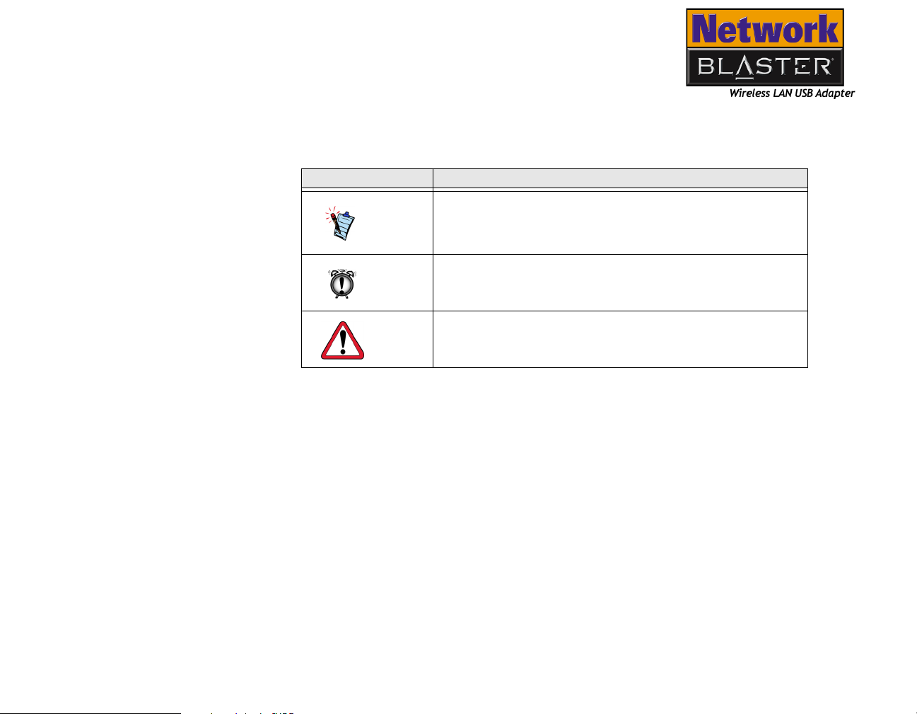
Document Conventions
This manual uses the following conventions to help you locate and identify the
information that you need.
Table i: Document conventions
Text Element Use
This notepad icon indicates information that is of
particular importance and should be considered
before continuing.
This alarm clock icon indicates that failure to
adhere to directions may result in loss of data or
damage to your system.
The warning sign indicates that failure to adhere to
directions may result in bodily harm or life
threatening situations.
Introduction xii
Page 14
1
About Wireless LAN
Page 15

About Wireless LAN
Wireless LAN
Installation
Cost
Speed
Mobility
Scalability
Wireless Local Area Network (WLAN), compared to a traditional wired LAN, is easy
to setup and manage, so it saves you time and money.
A WLAN combines data connectivity with user mobility. You can move around in a
room or move from one floor to another without being disconnected from the LAN.
In most companies, a wireless LAN is an extension of a wired network. However, in
small offices or hard-to-wire areas, it may be the only LAN solution.
Installing a WLAN is easy, convenient, and fast.
A WLAN is cost effective, as you do not have to install cables into your walls and
floors. Multiple Internet users can share a single IP address.
A WLAN provides data speeds of up to 11 Mbps, which increases the access rate to
shared resources.
Unlike wired networks, a WLAN allows you to move around on a floor or building, or
even across buildings, and still remain connected to the network.
You can choose to configure your WLAN to Ad-hoc mode or Infrastructure mode. In
Ad-hoc mode, a wireless computer (client) communicates with other wireless
stations directly. In Infrastructure mode, wireless clients connect to an access point
via radio waves, and the access point connects to other wireless and wired clients.
It is easy to configure a WLAN when you need to switch from one topology to
another.
About Wireless LAN 1-1
Page 16
Ad-hoc mode
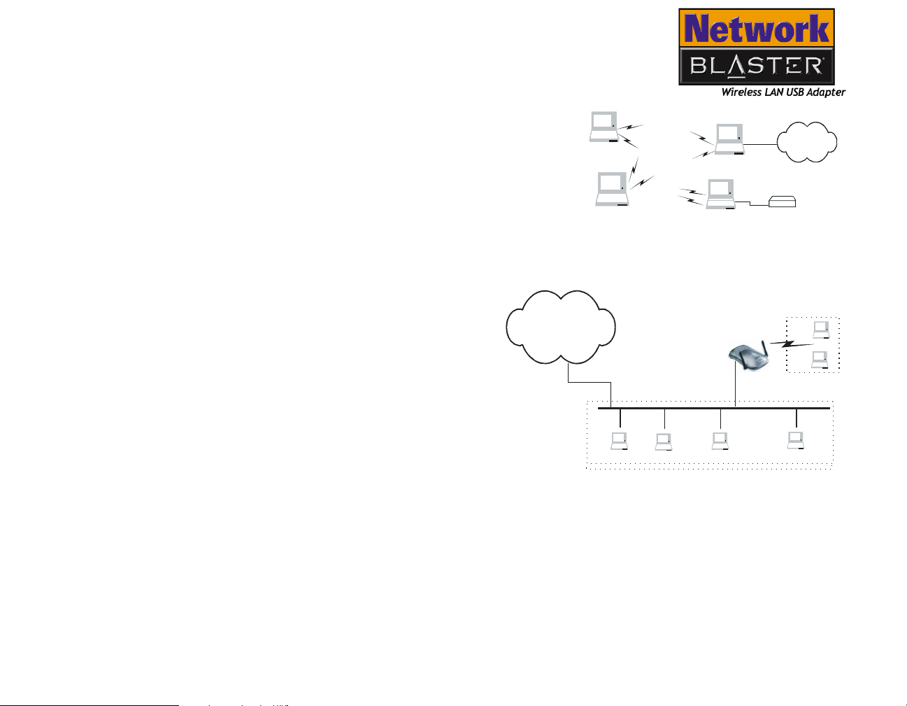
In an Ad-hoc network, also known as a Peerto-Peer network, each workstation in the
network is both a server and a wireless client.
Users on the network can share files,
printers, drives and other peripherals, and
access the Internet using a shared modem,
as shown in Figure 1-1. However, users can
only communicate with other WLAN
computers that are in the WLAN workgroup
and that are within a fixed range.
Internet
Printer
Figure 1-1: Ad-hoc network.
Infrastructure mode
Flexibility
In an Infrastructure network,
wireless clients connect to an
access point that is connected to
a wired LAN, as shown in Figure
Intern et
Intern et
Access Point
Wireless Clients
Wireless Clients
1-2. The access point allows a
user on a wireless LAN to access
an existing wired network, to
connect to the Internet, E-mail,
Ethernet LAN
Ethernet LAN
transfer files, and to share a
printer. Moreover, the access
point manages the bandwidth to
maximize bandwidth utilization.
Figure 1-2: Infrastructure network.
Adding new users and rearranging office space is convenient as it does not require
any additional wiring.
About Wireless LAN 1-2
Page 17

2
Installing Hardware
Page 18
Installing Hardware
Creative Network Blaster Wireless LAN USB Adapter 2030 is equipped with a USB
port that allows you to connect it to a computer. This chapter guides you through
the process of setting up your Wireless LAN USB Adapter to the USB port of a
desktop computer.
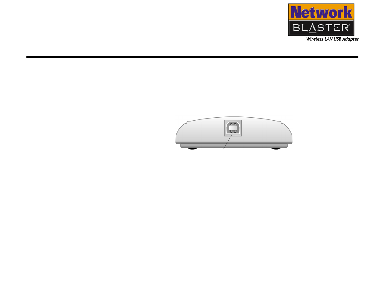
About Rear View of Wireless LAN USB Adapter
The USB port is located at the rear of the adapter (see Figure 2-1).
USB PORT
Figure 2-1: Rear view of the Network Blaster Wireless LAN
USB Adapter
Installing Hardware 2-1
Page 19

The Wireless LAN USB Adapter is
shown in Figure 2-2. It has a builtin antenna for the transmission and
reception of the radio frequency
(RF) waves.
Power LED Indicates power
status. The LED turns on when
Wireless LAN USB Adapter,
which gets its power from your
computer, is turned on.
Link LED Indicates link
status. The LED turns on
when the adapter is active.
USB port
Your Wireless LAN USB Adapter
comes with a USB cable that has
different types of USB connectors at
both ends (see Figure 2-3). The
type A connector of the USB cable is
the most common connector that
fits into a USB port of a desktop
computer. The type B connector of
the USB cable connects to the USB
port of your Wireless LAN USB
Adapter.
Figure 2-2: Network Blaster Wireless
LAN USB Adapter
Type A
Figure 2-3: The USB cable connectors
Installing Hardware 2-2
Type B
Page 20

3
Installing and Uninstalling
Drivers and Configuration Utility
Page 21
Installing and Uninstalling Drivers and Configuration Utility
Before you begin to install the drivers for your Creative Network Blaster Wireless
LAN USB Adapter 2030, be sure that your computer has USB ports and they are
enabled, as there are some motherboards with disabled USB ports. In addition,
Install the drivers only after
you have installed the
hardware.
some motherboards have USB interface with the USB ports extension but no ports,
which means that you should purchase your own USB port and plug it to your
computer’s motherboard’s USB interface. For more information on how to enable or
install the USB port extension with USB interface only, consult your motherboard
user guide or vendor.
Installing and Uninstalling Drivers and Configuration Utility 3-1
Page 22
Installing Drivers and Configuration Utility
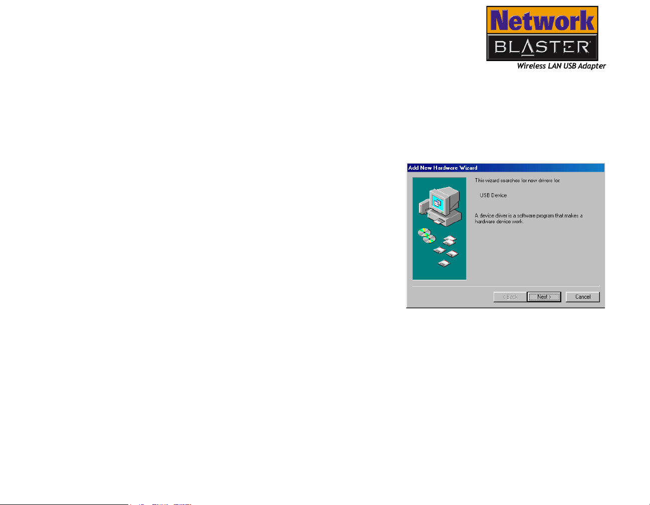
In Windows 98SE
1. Turn on your computer.
2. With the USB cable provided, connect
Wireless LAN USB Adapter to your
computer. Windows automatically
detects the USB device. The Add New
Hardware Wizard dialog box similar
to Figure 3-1 appears.
3. Click the Next button.
Figure 3-1: Add New Hardware
Wizard dialog box
Installing and Uninstalling Drivers and Configuration Utility 3-2
Page 23
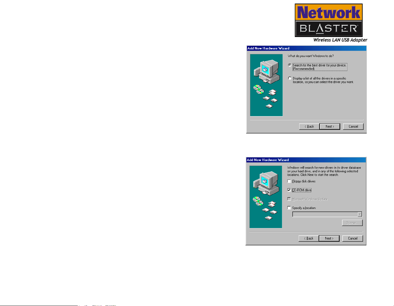
4. In the dialog box similar to Figure 3-2,
click the Search for the best driver
for your device (Recommended)
option, and click the Next button.
5. In the dialog box similar to Figure 3-3,
click the CD-ROM drive check box to
select it. Insert the installation CD into
the CD-ROM drive, and click the Next
button.
Installing and Uninstalling Drivers and Configuration Utility 3-3
Figure 3-2: Add New Hardware
Wizard dialog box
Figure 3-3: Add New Hardware
Wizard dialog box
Page 24
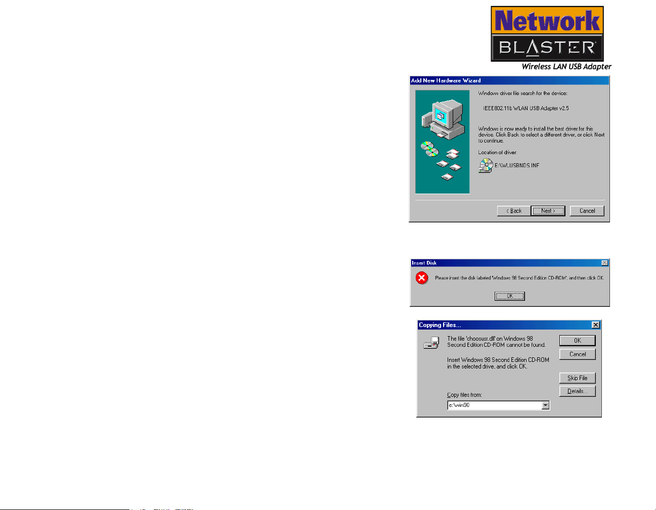
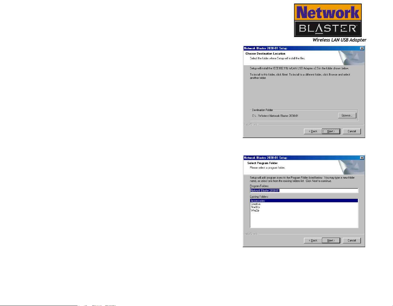
6. In the dialog box similar to Figure 3-4,
click the Next button.
7. If the message box similar to
Figure 3-5 appears, insert the Windows
98SE CD into the CD-ROM drive, then
click the OK button. The Copying Files
dialog box appears (see
Figure 3-5).
8. In the Copy files from box, type
E:\Win98 (where E: represents your
CD-ROM drive), and then click the OK
button.
Installing and Uninstalling Drivers and Configuration Utility 3-4
Figure 3-4: Add New Hardware
Wizard dialog box
Figure 3-5: Insert Disk message box and
Copying Files dialog box
Page 25
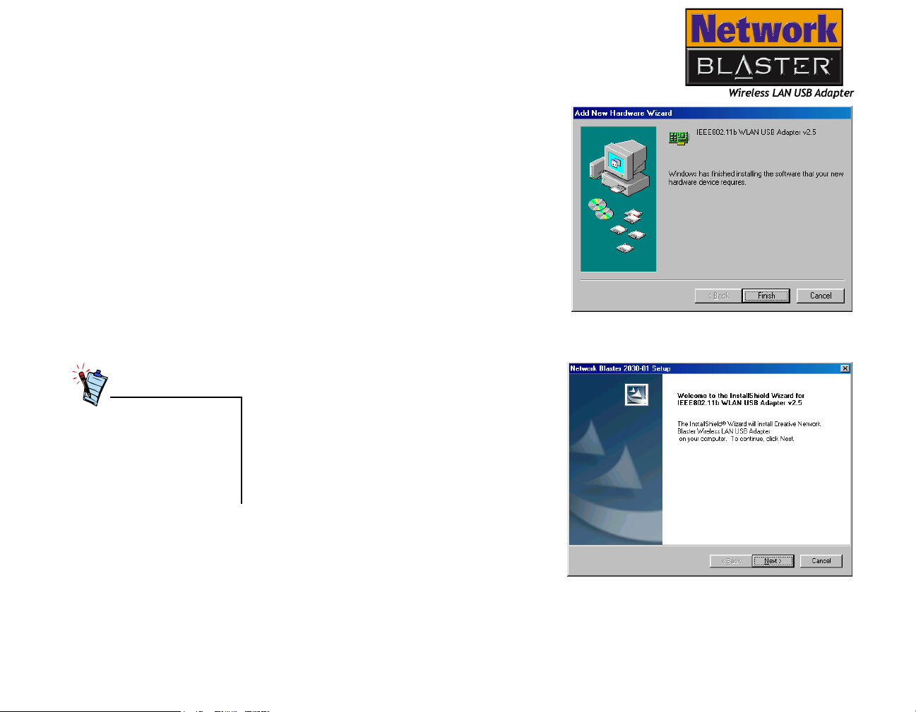
9. In the next dialog box similar to Figure
3-6, click the Finish button.
10.When prompted, restart your
computer.
Make sure the installation CD is in the
CD-ROM drive.
If the installation CD is not
inserted into the CD-ROM
drive, the Wireless Utility
Setup message appears
after the system restarts.
Insert the installation CD and
click the Retry button.
Figure 3-6: Add New Hardware
Wizard dialog box
11.After restarting your computer, the
Network Blaster 2030-01 Setup
dialog box similar to Figure 3-7
appears.
12.Click the Next button.
Figure 3-7: Network Blaster 2030-01
Setup dialog box
Installing and Uninstalling Drivers and Configuration Utility 3-5
Page 26
13.When the dialog box similar to Figure
3-8 appears, click the Next button.
14.When the dialog box similar to Figure
3-9 appears, click the Next button.
Installing and Uninstalling Drivers and Configuration Utility 3-6
Figure 3-8: Network Blaster 2030-01
Setup dialog box
Figure 3-9: Network Blaster 2030-01
Setup dialog box
Page 27
15.When the dialog box similar to Figure
3-10 appears, click the Next button.
16.When the dialog box similar to Figure
3-11 appears, click the Finish button.
Installing and Uninstalling Drivers and Configuration Utility 3-7
Figure 3-10:Network Blaster 2030-01
Setup dialog box
Figure 3-11:Network Blaster 2030-
01 Setup dialog box
Page 28
After you have installed the
Wireless LAN USB Adapter’s
drivers, you must configure
the Wireless LAN USB
Adapter’s settings. See
“Configuring the Wireless LAN
USB Adapter” on page 4-1.
Congratulations! You have successfully
installed the Wireless LAN USB Adapter’s
drivers and Configuration Utility. The
Configuration Utility icon (see Figure 3-12)
appears on the taskbar near the clock.
To close the Configuration Utility, right-click
its icon, and select Exit.
Figure 3-12:Configuration Utility
icon
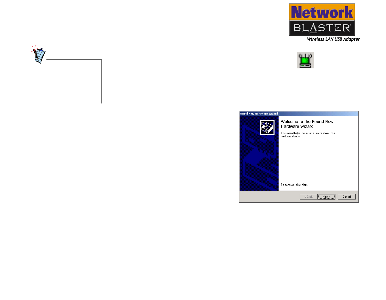
In Windows 2000
1. Turn on your computer.
2. With the USB cable provided, connect
Wireless LAN USB Adapter to your
computer. Windows automatically
detects the USB device. The Found
New Hardware Wizard dialog box
similar to Figure 3-13 appears.
3. Click the Next button.
Figure 3-13:Found New Hardware
Wizard dialog box
Installing and Uninstalling Drivers and Configuration Utility 3-8
Page 29
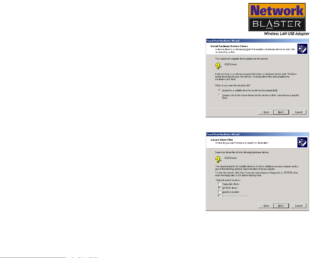
4. In the dialog box similar to Figure 3-14
appears, click the Search for a
suitable driver for your device
(recommended) option, and click the
Next button.
5. In the dialog box similar to Figure 3-15,
click the CD-ROM drives check box to
select it. Insert the installation CD into
the CD-ROM drive, and click the Next
button.
Installing and Uninstalling Drivers and Configuration Utility 3-9
Figure 3-14:Found New Hardware
Wizard dialog box
Figure 3-15:Found New Hardware
Wizard dialog box
Page 30

6. In the dialog box similar to
Figure 3-16, click the Next button.
7. If the dialog box similar to Figure 3-17
appears, click the Yes button.
Installing and Uninstalling Drivers and Configuration Utility 3-10
Figure 3-16:Found New Hardware
Wizard dialog box
Figure 3-17:Digital Signature Not
Found dialog box
Page 31

8. In the dialog box similar to
Figure 3-18, click the Finish button.
9. In the Network Blaster 2030-01
Setup dialog box similar to
Figure 3-19, click the Next button.
Installing and Uninstalling Drivers and Configuration Utility 3-11
Figure 3-18:Found New Hardware
Wizard dialog box
Figure 3-19:Network Blaster 2030-01
Setup dialog box
Page 32

10.When the dialog box similar to Figure
3-20 appears, click the Next button.
11.When the dialog box similar to Figure
3-21 appears, click the Next button.
Installing and Uninstalling Drivers and Configuration Utility 3-12
Figure 3-20:Network Blaster 2030-01
Setup dialog box
Figure 3-21:Network Blaster 2030-01
Setup dialog box
Page 33

12.When the dialog box similar to Figure
3-22 appears, click the Next button.
13.When the dialog box similar to Figure
3-23 appears, click the Finish button.
Installing and Uninstalling Drivers and Configuration Utility 3-13
Figure 3-22:Network Blaster 2030-01
Setup dialog box
Figure 3-23:Network Blaster 2030-01
Setup dialog box
Page 34

After you have installed the
Wireless LAN USB Adapter’s
drivers, you must configure
the Wireless LAN USB
Adapter’s settings. See
“Configuring the Wireless LAN
USB Adapter” on page 4-1.
Congratulations! You have successfully
installed the Wireless LAN USB Adapter’s
drivers and Configuration Utility. The
Configuration Utility icon (see Figure 3-24)
appears on the taskbar near the clock.
To close Configuration Utility, right-click its
icon, and select Exit.
Figure 3-24:Configuration Utility
icon
In Windows Me
1. Turn on your computer.
2. With the USB cable provided, connect
Wireless LAN USB Adapter to your
computer. Windows automatically
detects the USB device. The Add New
Hardware Wizard dialog box similar
to Figure 3-25 appears.
3. Click the Automatic search for a
better driver (Recommended)
option. Insert the installation CD into
the CD-ROM drive, and click the Next
button.
Figure 3-25:Add New Hardware Wizard
dialog box
Installing and Uninstalling Drivers and Configuration Utility 3-14
Page 35

4. In the dialog box similar to
Figure 3-26, click the Finish button.
5. When prompted, restart your
computer.
Make sure the installation CD is in
the CD-ROM drive.
Figure 3-26:BritePort Wireless LAN USB Adapter
Setup Program dialog box
Installing and Uninstalling Drivers and Configuration Utility 3-15
Page 36

If the installation CD is not
inserted into the CD-ROM
drive, the Wireless Utility
Setup message appears after
the system restarts. Insert
the installation CD and click
the Retry button.
6. After restarting your computer, the
Network Blaster 2030-01 Setup
dialog box similar to Figure 3-27
appears.
7. Click the Next button.
Figure 3-27:BritePort Wireless LAN USB Adapter
Setup Program dialog box
8. When the dialog box similar to
Figure 3-28 appears, click the Next
button.
Figure 3-28:Network Blaster 2030-01
Installing and Uninstalling Drivers and Configuration Utility 3-16
Setup dialog box
Page 37

9. When the dialog box similar to Figure
3-29 appears, click the Next button.
10.When the dialog box similar to Figure
3-30 appears, click the Next button.
Installing and Uninstalling Drivers and Configuration Utility 3-17
Figure 3-29:Network Blaster 2030-01
Setup dialog box
Figure 3-30:Network Blaster 2030-01
Setup dialog box
Page 38

After you have installed the
Wireless LAN USB Adapter’s
drivers, you must configure
the Wireless LAN USB
Adapter’s settings. See
“Configuring the Wireless LAN
USB Adapter” on page 4-1.
11.When the dialog box similar to
Figure 3-31 appears, click the
Finish button. If prompted, restart
your computer.
Figure 3-31:BritePort Wireless LAN USB Adapter
Congratulations! You have successfully
installed the Wireless LAN USB Adapter’s
drivers and Configuration Utility. The
Configuration Utility icon appears on the
taskbar near the clock (see Figure 3-32).
To close Configuration Utility, right-click its
icon, and select Exit.
Setup Program dialog box
Figure 3-32:Configuration Utility
icon
Installing and Uninstalling Drivers and Configuration Utility 3-18
Page 39

In Windows XP
1. Turn on your computer.
2. With the USB cable provided, connect
Wireless LAN USB Adapter to your
computer. Windows automatically
detects the USB device. The Found
New Hardware Wizard dialog box
similar to Figure 3-33 appears.
3. Insert the installation CD into the
CD-ROM drive, and click the Install
the software automatically
(Recommended) option.
4. Click the Next button.
Figure 3-33:Found New Hardware
Wizard dialog box
Installing and Uninstalling Drivers and Configuration Utility 3-19
Page 40

5. In the dialog box similar to
Figure 3-34, click the Finish button.
Figure 3-34:Microsoft warning message
Figure 3-34:Found New Hardware
Wizard dialog box
Installing and Uninstalling Drivers and Configuration Utility 3-20
Page 41

If the Network Blaster 2030-01
Setup dialog box does not
appear, go to the Start menu and
click Run. In the Run dialog box,
type in E:\wlsetup.exe (where E:
can be replaced by the actual
letter assigned to your CD-ROM
drive) and click the OK button.
6. In the Network Blaster 2030-01
Setup dialog box similar to
Figure 3-35, click the Next button.
Figure 3-35:Network Blaster 2030-01
Setup dialog box
7. When the dialog box similar to Figure
3-36 appears, click the Next button.
Figure 3-36:Network Blaster 2030-01
Installing and Uninstalling Drivers and Configuration Utility 3-21
Setup dialog box
Page 42

8. After the dialog box similar to Figure
3-37 appears, click the Next button.
9. When the dialog box similar to Figure
3-38 appears, click the Next button.
Figure 3-37:Network Blaster 2030-01
Setup dialog box
Figure 3-38:Network Blaster 2030-01
Installing and Uninstalling Drivers and Configuration Utility 3-22
Setup dialog box
Page 43

10.When the dialog box similar to Figure
3-39 appears, click the Finish button.
Figure 3-39:Network Blaster 2030-01
Setup dialog box
Installing and Uninstalling Drivers and Configuration Utility 3-23
Page 44

After you have installed the
Wireless LAN USB Adapter’s
drivers, you must configure
the Wireless LAN USB
Adapter’s settings. See
“Configuring the Wireless LAN
USB Adapter” on page 4-1.
Congratulations! You have successfully
installed the Wireless LAN USB Adapter’s
drivers and Configuration Utility. The
Configuration Utility icon (see Figure 3-40)
appears on the taskbar near the clock.
To close Configuration Utility, right-click its
icon, and select Exit.
Figure 3-40:Configuration Utility
icon
Installing and Uninstalling Drivers and Configuration Utility 3-24
Page 45

Uninstalling Drivers and Configuration Utility
At times, you may need to uninstall, and then reinstall the drivers to correct
problems, or make version upgrades. The following instructions tell you how to
uninstall the applications in all Windows operating systems:
1. Close all applications.
2. Click Start -> Programs (or All Programs) -> Network Blaster 2030-01 ->
Uninstall.
The Confirmation Uninstallation dialog box appears.
3. Click the OK button.
If the Shared File Detected dialog boxes appear, click the No button.
4. If prompted, restart your computer.
Installing and Uninstalling Drivers and Configuration Utility 3-25
Page 46

Configuring the Wireless LAN
4
USB Adapter
Page 47

Configuring the Wireless LAN USB Adapter
Before you use the Creative Network Blaster Wireless LAN USB Adapter 2030, you
may want to configure the card in the Configuration Utility.
Refer to the Glossary chapter
for definitions of technical
terms.
If you want to use your computer in Peer-to-Peer network or Ad-hoc mode, all the
wireless stations must have the same settings for Service Set Identifier (SSID),
channel, and Wired Equivalent Privacy (WEP) if any. For more information, see “Adhoc mode” on page 1-2.
In the Infrastructure mode, the wireless stations and the Access Point must have
the same settings for SSID and WEP (if any). For more information, see
“Infrastructure mode” on page 1-2.
Configuration Utility Icon
The Configuration Utility icon (Figure 4-1)
appears on your computer taskbar after you
have installed the drivers and Configuration
Utility. It does not appear if the Wireless LAN
USB Adapter is not connected to your
computer.
The color of the Configuration Utility icon tells you the status of the Wireless LAN
USB Adapter:
Green: In the Infrastructure mode, you are connected to an access point and the
radio frequency (RF) signal strength is good. However, this does not ensure that
your computer will be able to communicate with the access point.
In the Ad-hoc mode, the icon is always green, except while scanning the network.
Yellow: You are connected to an access point and the signal strength is poor.
Red: In Infrastructure or Ad-hoc mode, you are scanning the network.
Configuring the Wireless LAN USB Adapter 4-1
Figure 4-1: Configuration Utility
icon
Page 48

Configuring Settings
The Link Quality and Signal
Strength information appear
only in the default
Infrastructure mode, and
not in Ad-hoc mode.
1. If the Configuration Utility icon does not appear on the taskbar, click Start ->
Programs (or All Programs)-> Network Blaster 2030-01 -> Network
Blaster Wireless LAN USB Adapter utility.
2. Double-click the Configuration Utility icon on the taskbar just near the clock
(see Figure 4-1). The Configuration Utility dialog box similar to Figure 4-2
appears.
3. Click the Link Info tab. The status of your wireless connection is displayed.
4. Click the Re-Scan button to locate and re-connect the network.
State box
Displays the MAC Address of the network device
which is currently connected to your Wireless LAN
USB adapter.
Current Channel box
Displays the channel that the
Wireless LAN USB Adapter is
operating in.
Current Service Set Identifier box
Displays the SSID of the connected network device
Figure 4-2: Link Info tab
Configuring the Wireless LAN USB Adapter 4-2
Page 49

Configuration Settings
A profile is a set of
pre-defined values.
Service Set Identifier
(SSID) is case sensitive.
1. Click the Configuration tab (see
Figure 4-3). In this tab, you can change the
default configuration settings below.
2. To create a new profile, click the Profile
box, and then type a name in the box.
3. Click the Create button.
4. To switch between profiles, click the Profile
box, and then click the profile that you
want.
5. Click the Activate button.
6. To remove a profile, click the Profile box,
and then click the profile that you want.
7. Click the Remove button.
8. Click the Operating Mode box.
If you are connecting to a network through
an access point, click Infrastructure.
Figure 4-3: Configuration tab
If you are connecting to a network without
an access point, click Ad-hoc.
9. Click the Service Set Identifier (SSID) box.
In Infrastructure mode, set the SSID to the SSID of the access point.
In Ad-hoc mode, set the SSID to the SSID of the Ad-hoc station you want to
connect.
10.Click the Transfer Rate box, and then click the transfer rate that you want.
11.Click the Channel box.
In Infrastructure mode, you need not set the channel. The channel for the access
point is already set for you.
In Ad-hoc mode, set the channel to the channel of the Ad-hoc station you want
to connect.
Configuring the Wireless LAN USB Adapter 4-3
Page 50

12.To set the Wireless LAN USB Adapter to power saving mode, click the Power
Saving Mode box, and then click Enabled.
In Ad-hoc mode, the Power Saving Mode is not supported.
13.Click the Apply Changes button to save the settings.
Site Survey Settings
The entries in the Link Info
tab is automatically updated
to reflect the selected Access
Point or ad-hoc station.
1. Click the Site Survey tab (see Figure 4-4).
2. Click the Search button to display or
refresh the list of available Access Points or
ad-hoc stations.
3. Click the Access Point or a wireless network
device you want to link with.
4. Click the Connect button.
Your computer automatically connects to
the selected Access Point or wireless
network device.
Figure 4-4: Site Survey tab
Configuring the Wireless LAN USB Adapter 4-4
Page 51

Encryption Settings
•For Wired Equivalent
Privacy (WEP) you have
three options: Disabled,
64 Bits, and 128 Bits.
All wireless network
devices in a Local Area
Network (LAN) must have
the same WEP settings
and WEP key entry for
this feature to work. If
WEP is disabled, the data
is not encrypted before
being transmitted. To
enable encryption, you
must select either 64 Bits
or 128 Bits.
• The type of Encryption
option to use depends on
your Access Point
encryption settings.
• Use “0”s for unused keys.
1. Click the Encryption tab (see Figure 4-5).
To enable WEP, click the Encryption (WEP)
box, and then click the number of bits that
you want.
2. The type of encryption option depends on
your access point encryption settings. If you
want to create a WEP key entry using a
passphrase, click the Create with
Passphrase option, and then type a series
of alphanumeric characters in the
Passphrase box. A series of hexadecimal
values will be created automatically.
3. If you want to create a WEP key entry
manually, click the Manual Entry option.
By default, hexadecimal values are used.
For more information, see “Hexadecimal” on
page D-4.
Figure 4-5: Encryption tab
4. If you want to use ASCII code for the
encryption keys, click the ASCII check box to select it, and then complete the
key table with random ASCII characters. Initially, you may need to fill in all the
key entries. These keys serve as passwords that encrypt your data before
transmission.
5. Click the Default Tx Key box, and then click the key that you want to use to
encrypt your data with.
6. Click the Apply Changes button to save the settings.
Configuring the Wireless LAN USB Adapter 4-5
Page 52

Advanced Settings
You are advised to use the
manufacturer’s default values.
If you have changed the
original settings, and would
like to return to the default
settings, click the Restore
Defaults button.
1. Click the Advanced tab (see Figure 4-6).
2. Click and drag the Fragmentation
Threshold and RTS/CTS Threshold
sliders to the rate you want.
3. The Security box will only be highlighted
when WEP is enabled. Click the
Authentication Type box, and then click
the option that matches your access point.
4. Click the Preamble Type box, and then
click the preamble type that you want.
5. Click the Apply Changes button to save the
settings.
Figure 4-6: Advanced tab
Configuring the Wireless LAN USB Adapter 4-6
Page 53

Utility Information
1. Click the About tab (see Figure 4-7). This
displays the driver, configuration utility and
firmware versions.
2. Click the OK button.
Figure 4-7: About tab
Configuring the Wireless LAN USB Adapter 4-7
Page 54

Configuring
Settings In
You can choose to configure your Wireless LAN USB Adapter using the Wireless
Network Connection in Windows XP, or the Configuration Utility provided in the
installation CD.
Windows XP
Using the Wireless Network Connection
To configure your Wireless LAN USB Adapter using the Wireless Network Connection,
go to “Using the Wireless Network Connection” on page 4-8.
To configure your Wireless LAN USB Adapter using the Configuration Utility, go to
“Using the Configuration Utility” on page 4-12.
1. After you install the drivers, the Wireless Network Connection icon appears
on the taskbar.
2. Right-click the Wireless Network Connection icon (Figure 4-8)
on the taskbar, and then click View Available Wireless
Networks.
3. When the Connect to Wireless Network dialog
box similar to Figure 4-9 appears, click the
available network that you want.
If necessary, enter the WEP key in the Network
key field.
4. Click the Connect button. Your computer
automatically connects to the selected network.
Figure 4-9: Connect to Wireless
Network dialog box
Figure 4-8
Configuring the Wireless LAN USB Adapter 4-8
Page 55

Encryption settings
If you cannot find your Access
Point, click the Refresh
button.
1. Right-click the Wireless Network Configuration icon on the taskbar, and then
click View Available Networks.
2. When the Connect to Wireless Network dialog box similar to Figure 4-9
appears, click the Advanced button.
3. A Wireless Network Connection Properties
dialog box similar to Figure 4-10 will pop up.
If your Access Point or ad-hoc server appears in
the Preferred Networks section, click on it and click
the Properties button.
If your Access Point or ad-hoc server does not
appear in the Preferred networks section, then
click the Refresh button, the click the network
that you want from the list of available networks,
then click the Configure button.
Figure 4-10:Wireless Network
Configuring the Wireless LAN USB Adapter 4-9
Connection
Properties dialog
box
Page 56

•For Wired Equivalent
Privacy (WEP) you have
three options: Disabled,
64 Bits (40-bits), and
128 Bits (104 bits). All
wireless network devices
in a Local Area Network
(LAN) must have the
same WEP settings and
WEP key entry for this
feature to work. If WEP is
disabled, the data is not
encrypted before being
transmitted. For enabling
encryption, you must
select either 64 Bits or
128 Bits.
• The type of Encryption
option to use depends on
your Access Point
encryption settings.
4. When the Wireless Network Properties dialog
box similar to Figure 4-11 appears, click the Data
Encryption (WEP enabled) check box to select it.
5. Click the The key is provided for me
automatically check box to deselect it.
6. Complete the Network key box with random
hexadecimal values or ASCII characters. These keys
serve as passwords that encrypt your data before
transmission.
7. Click the OK button.
Figure 4-11:Wireless Network
Properties dialog
box
Configuring the Wireless LAN USB Adapter 4-10
Page 57

Network Status
The Wireless Network
Connection status dialog box
will not appear if the Wireless
LAN USB adapter is not
currently connected to a
wireless network.
1. Double-click the Wireless Network Connection icon on the taskbar.
2. When the Wireless Network Connection Status
dialog box similar to Figure 4-12 appears, click the
General tab. This displays the connection status,
duration, speed and signal strength.
Figure 4-12:Wireless Network
Connection Status
dialog box
3. Click the Support tab. A dialog box similar to
Figure 4-13 that displays the address type, IP
address, subnet mask and default gateway
appears.
Figure 4-13:Wireless Network
Configuring the Wireless LAN USB Adapter 4-11
Connection Status
dialog box
Page 58

Using the Configuration Utility
When Wireless Network
Connection is enabled, you
cannot use the
Configuration Utility to
configure the settings.
Therefore, the Wireless
Network Connection needs
to be disabled.
1. Right-click the Configuration Utility icon (Figure 4-1) on the taskbar, and then
click Exit.
2. Right-click the Wireless Network Connection icon (Figure 4-8) on the taskbar,
and then click View Available Wireless Networks.
3. When the Connect to Wireless Network dialog box similar to Figure 4-9
appears, click the Advanced button.
4. When the Wireless Network Connection Properties dialog box similar to
Figure 4-10 appears, click the Use Windows to configure my wireless
network settings check box to clear it. If you want to use the Wireless Network
Connection later, be sure to click this check box to select it.
5. Click the OK button.
For the remaining steps, refer to “Configuring Settings” on page 4-2.
Configuring the Wireless LAN USB Adapter 4-12
Page 59

Notes on Wireless LAN Configuration
When configuring a wireless LAN (WLAN), take note of the following points:
❑ Start by determining the areas to be networked, the number of users and the
type of devices to be used. Then determine the number of Access Points required
and where they should be placed.
❑ An Access Point provides a data rate of up to 11 Mbps, which is shared by all
wireless clients in the area covered by the Access Point. If two Access Points are
placed close to each other, they can simultaneously provide a data rate of up to
22 Mbps. However, they must operate in non-overlapping channels. Two Access
Points placed close to each other and operating on the same channel can provide
only one 11 Mbps per channel.
❑ Optimize the performance of the WLAN by ensuring that the distance between
two Access Points is not too large. In most buildings, WLAN cards operate within
a range of 100 to 300 feet (30 to 91 meters), depending on the thickness and
structure of the walls. Under normal conditions, an Access Point provides a
coverage of up to 150 feet (46 meters). However, in offices with walls or cube
walls, the coverage is only around 80 feet (24 meters).
❑ Radio waves can pass through walls and glass but not metal. If the signal on the
other side of a wall is weak, it may be that the wall has reinforcing metal in its
structure. Install another Access Point to circumvent this problem or move the
Access Point to another location.
❑ Floors usually have metal girders and metal reinforcing struts that weaken radio
waves.
Configuring the Wireless LAN USB Adapter 4-13
Page 60

5
Configuring Your Computer’s
Network Settings
Page 61

Configuring Your Computer’s Network Settings
This chapter explains how to configure your computer’s network settings in
Windows 98 SE, Windows Me, Windows 2000 and Windows XP.
Before you begin to configure a computer, be sure that the computer has a
functioning Network Interface Card (NIC). If your computer is a wireless client of the
Wireless LAN Access Point 2100, the Wireless LAN USB Adapter 2030 is your NIC.
Network Configuration in Windows 98 SE/ Me
1. Start -> Settings -> Control Panel.
2. Double-click the Network icon.
3. When the dialog box similar to Figure 5-1
appears, click the Configuration tab.
4. Click your Ethernet card to highlight it, for
example, TCP/IP->PRO/100+
Management Adapter (10/100) and
then click the Properties button.
Figure 5-1
Configuring Your Computer’s Network Settings 5-2
Page 62

5. When the dialog box similar to Figure 5-2
appears, click the IP Address tab.
If you are using a Dynamic IP address,
proceed to step 6. For users with a Static IP
address, go to step 8.
6. Click the Obtain an IP address
automatically option to select it and click
the OK button.
7. Click the OK button.
8. When Windows prompts you to restart your
computer, click the Yes button to restart
your computer.
This completes the Ethernet configuration,
therefore skip the remaining steps.
9. Click the Specify an IP Address option to
select it.
10.Type the relevant information in the IP
Address and Subnet Mask boxes, and
then click the Gateway tab.
11.When the dialog box similar to Figure 5-3
appears, type the new gateway address in
the New gateway box, and then click the
Add button.
12.Click the DNS Configuration tab
Figure 5-2
Figure 5-3
Configuring Your Computer’s Network Settings 5-3
Page 63

13.When the dialog box similar to Figure 5-4
appears, click the Enable DNS option to
select it.
14.Type the relevant information in the Host,
Domain and DNS Server Search Order
boxes and then click the Add button.
15.Click the OK button.
16.Click the OK button.
17.When Windows prompts you to restart your
computer, click the Yes button to allow the
settings to take effect and complete your
configuration.
Figure 5-4
Configuring Your Computer’s Network Settings 5-4
Page 64

Network Configuration in Windows 2000
1. Start -> Settings -> Control Panel.
2. Double-click the Network icon.
3. Right-click the Local Area Connection
icon and then click Properties from the list
to select it.
4. When the dialog box similar to Figure 5-5
appears, select Internet Protocol (TCP/
IP) and then click the Properties button.
5. When the dialog box similar to Figure 5-6
appears, click the Obtain an IP address
automatically option and proceed to
step 7 If you are using a Dynamic IP
Address. Continue with step 6 if you are
using a static IP address.
6. Click the Use the following IP Address
option to select it and type the relevant
information in the IP Address, Subnet
mask, Default gateway, Preferred DNS
server and Alternate DNS server boxes.
7. Click the OK button.
8. When the Local Area Connection
Properties dialog box appears, click the
OK button to complete the configuration.
Figure 5-5
Figure 5-6
Configuring Your Computer’s Network Settings 5-5
Page 65

Network Configuration in Windows XP
1. Start -> Control Panel.
2. Double-click the Network Connections
icon.
3. Right-click the Local Area Connection
icon and then click Properties from the list
to select it.
4. When the dialog box similar to Figure 5-7
appears, select Internet Protocol (TCP/
IP) and then click the Properties button.
Figure 5-7
Configuring Your Computer’s Network Settings 5-6
Page 66

5. When the dialog box similar to Figure 5-8
appears, click the Obtain an IP address
automatically option and proceed to
step 7 If you are using a Dynamic IP
Address. Continue with step 6 if you are
using a static IP address.
6. Click the Use the following IP Address
option to select it and type the relevant
information in the IP Address, Subnet
mask, Default gateway, Preferred DNS
server and Alternate DNS server boxes.
7. Click the OK button.
8. When the Local Area Connection
Properties dialog box appears, click the
OK button to complete the configuration.
Figure 5-8
Configuring Your Computer’s Network Settings 5-7
Page 67

A
General Specifications
Page 68

Specifications
This appendix lists the general specifications of your wireless LAN USB adapter.
Wireless Interface
USB Interface
Antenna
Frequency Range
Modulation
Channels
Data Rate
Output Power
Coverage Area (outdoor)
Power Supply
❑ IEEE 802.11b compliant
❑ WEP security support (64-bit or 128-bit encryption)
❑ Compliant to 1.0 and 1.1 standards
❑ Built-in antenna
❑ 2.4 - 2.4835 GHz (ISM Band)
❑ DSSS - Direct Sequence Spread Spectrum
❑ 11 Channels
❑ 11/5.5/2/1 Mbps
❑ 15 dBm (typical)
❑ Up to 390 meters (1287 feet)
❑ Derives power from the USB bus
Specifications A-1
Page 69

Indicator LEDs
❑ Power LED
❑ Link LED
Safety and Regulatory
Physical Dimensions
Wei g ht
❑ FCC Part 15 Class B, CE
❑ 4.6 inches (117 mm) x 2.1 inches (82 mm) x 1.0 inches (26 mm)
❑ 4.2 oz (120 g)
Specifications A-2
Page 70

B
Troubleshooting
Page 71

Troubleshooting
This appendix provides tips and solutions for resolving some of the problems you
might encounter with the Creative Network Blaster Wireless LAN USB Adapter 2030
either during installation or normal use.
Problems with Wireless LAN USB Adapter
In Windows 98SE/ Me/2000
Windows does not auto-detect the new USB device and the Add New Hardware
Wizard dialog box does not appear.
To solve this problem, refer to the following section that corresponds to your
Windows operating system.
1. Right-click the My Computer icon on your desktop and select Properties.
2. Click the Device Manager tab.
3. Click the View devices by type option and scroll down. Be sure that you see
Universal Serial Bus controllers. If it’s not there, refer to your motherboard
user guide and be sure that your motherboard supports USB.
4. Expand Universal Serial Bus controllers by clicking the plus sign next to it and
you will see the name of the controller bus and USB Root Hub. Be sure that there
is no red “X” or yellow “!” next to them. The red “X” or yellow “!” signs indicates
incorrect or incomplete installation.
5. Click the Remove button to remove the items with the red “X” or yellow “!”
6. Reinstall the drivers for Wireless LAN USB Adapter. For more information, see
“Installing and Uninstalling Drivers and Configuration Utility” on page 3-1.
Troubleshooting B-1
Page 72

In Windows XP
1. Click Start -> Control Panel.
2. Double-click the System icon. The System Properties dialog box appears.
3. Click the Hardware tab.
4. Click the Device Manager button.
5. Click the plus sign next to Universal Serial Bus controllers. The name of the
controller bus appears. Be sure that there is no red “X” or yellow “!” next to it.
The red “X” or yellow “!” signs indicates incorrect or incomplete installation.
6. Click any items with the red “X” or yellow “!”, and then click the Remove button.
7. Reinstall the drivers for Wireless LAN USB Adapter. For more information, see
“Installing and Uninstalling Drivers and Configuration Utility” on page 3-1.
Problems with Software
The Configuration Utility icon on the status bar is always red.
Do the following:
❑ If you are in Infrastructure mode, be sure that your computer and the access
point have the same SSID and WEP settings. The SSID is case sensitive. See
“Configuring Settings” on page 4-2.
❑ If you are in Ad-hoc mode, be sure that all the wireless stations use the same
SSID, channel, and WEP settings.
❑ Make sure that all the wireless stations are within range of each other.
❑ Restart the access point.
❑ Restart your computer.
❑ In the Advanced tab (see “Advanced Settings” on page 4-6), make sure that
Shared or Auto is selected in the Authentication Type box.
Troubleshooting B-2
Page 73

My computer is unable to establish a link with an access point.
Do the following:
❑ Make sure that the access point is connected and turned on. Observe the status
LEDs to make sure that the access point is properly connected.
❑ Make sure that your PC (wireless client) is set to Infrastructure mode.
❑ Make sure that the wireless USB adapter is connected to your computer. Also
make sure that you have installed the driver properly.
❑ Make sure that your computer is configured with the same SSID as the Wireless
Access Point. Also remember that the SSID is case sensitive.
❑ Your computer and the Access Point must have the same settings for WEP (Wired
Equivalent Privacy). If WEP is disabled on the Access Point, it must be disabled
on the computer. If WEP is enabled, the key tables must match.
❑ The authentication type and the Access Point must have the same settings or
make sure that Auto is selected in the Authentication Type box (see “Advanced
Settings” on page 4-6).
❑ Reset the Access Point.
❑ Restart your computer.
My computer is unable to connect to another wireless client.
Do the following:
❑ Make sure that the SSID is same for all the wireless clients and the Access Point.
❑ Check if you have a valid IP address and Subnet Mask. To find this out:
In Windows 98 SE/Me
1. Click the Start button and click Run.The Run dialog box appears.
2. In the Open box, type winipcfg.
3. Click the OK button. Circle the pull down list to select the specified device.
4. Restart your computer
Troubleshooting B-3
Page 74

In Windows 2000/XP
1. Click the Start button and click Run.The Run dialog box appears.
2. In the Open box, type command.
3. At the command prompt, type ipconfig.
4. Press the Enter key.
5. Restart your computer.
Radio Interference.
Do the following:
❑ Adjust the antennas of the wireless access point until you get the best reception.
❑ Keep the access point and wireless clients away from microwave ovens, large
metal objects and 2.4 GHz cordless phones.
❑ If possible move the access point from its present location to another location
until you get the best reception.
If the Network Blaster 2030-01 Setup dialog box does not appear
Do the following:
❑ Go to the Start menu
❑ Click on the Run command
❑ Type in E:\wlsetup.exe (where E: can be replaced by the actual drive letter
assigned to your CD-ROM) in the prompt.
❑ Click the OK button.
Troubleshooting B-4
Page 75

Frequently Asked Questions
C
(FAQs)
Page 76

Frequently Asked Questions (FAQs)
This appendix provides frequently asked questions you might have about Creative
Network Blaster Wireless LAN USB Adapter 2030 either during installation or normal
use.
What is the function of the Creative Network Blaster Wireless LAN USB Adapter?
It is a wireless network adapter card. Connect the wireless LAN USB adapter to your
computer, and the computer becomes a wireless station, which can transmit and
receive radio frequency (RF) signals. It can now communicate with other wireless
stations. Your computer can also be connected to a wired local network through an
Access Point and share network resources.
What is a wireless LAN?
A wireless LAN links the network users to LAN services through radio frequency
waves (RF) or wireless connection. In most companies, it is an extension of a wired
network, however in many small offices or hard-to-wire areas; it may be the only
LAN solution. A wireless LAN allows workers to roam freely around a floor area,
building, or multiple buildings, and still remain continuously connected to the
network.
How do I physically connect the Creative Network Blaster Wireless LAN USB
Adapter to my computer?
Connecting the Adapter to a computer is very easy. The Adapter has a USB port.
Connect the supplied USB cable to the USB port of the Adapter, and connect the
other end of the USB cable to a USB port on the computer. Windows operating
system will automatically detect the new hardware device and you will be required
to load the driver software from the Adapter’s CD-ROM.
Frequently Asked Questions (FAQs) C-1
Page 77

What is a Wireless Access Point?
Wireless Access Point (AP) is a network bridge that provides an easy and quick
solution for the wireless stations to access an existing wired local area network. An
Access Point extends the reach and usefulness of the wired network resources.
When you connect a Wireless AP to an Ethernet port of a hub or switch on your wired
LAN, many wireless clients can also access the network resources. Radio frequency
(RF) waves link the wireless clients to an AP, and the AP works as a bridge between
the wireless clients and the wired LAN or Ethernet clients.
What devices will cause interference with a wireless LAN?
A wireless LAN compliant to IEEE 802.11b operates in the 2.4 GHz frequency band.
Other products that operate in this frequency band, such as microwave ovens and
2.4 GHz cordless phones, can cause interference.
What are DSSS and FHSS?
DSSS and FHSS are two different digital modulation techniques that use spread
spectrum transmission methods. With FHSS, the data rates are limited to 2 Mbps,
while DSSS provides data rates up to 11 Mbps. In DSSS, the large bandwidth is
effectively split into frequency channels and the signal is then spread across the
channels in a predetermined pseudo random sequence. In DSSS, the digital data is
encoded with a series of codes.
How secure is my wireless connection?
Wireless Access Point and clients that adhere to 802.11b standard use DSSS (Direct
Sequence Spread Spectrum) technology. This technology has an inherent security
feature called scrambling, which makes it difficult for an intruder to intercept and
decipher the encoded wireless data. For enhanced security, your wireless network
must use a unique SSID. You can also enable the WEP function so that the data is
encrypted before being transmitted.
Frequently Asked Questions (FAQs) C-2
Page 78

Windows 2000 and Windows Me have a few security features. Windows 98SE users
can download security related patches from Microsoft’s web site. However, it is
recommended that you develop safe computing habits:
❑ Protect your passwords. Do not divulge the passwords to anyone and be
especially careful if someone asks you for the password online or over the phone.
❑ Protect your online transactions by using a secure browser.
❑ Before typing your credit card and other important information online, make sure
that the web site is secure and trustworthy.
❑ For computer folders that contain confidential and financial information, disable
the “File Sharing” option.
❑ Whenever you are not using your computer for a long time, turn off your
computer or disconnect the wireless LAN USB adapter.
❑ Use anti-virus software, as well as intrusion detection software and update it
regularly.
❑ Do not open email attachments unless you trust the sender and his identity.
❑ Do not download files and software from unreliable sources.
Frequently Asked Questions (FAQs) C-3
Page 79

D
Glossary
Page 80

Glossary
This appendix explains the technical terms used in this manual.
Access Point
Ad-hoc mode
Antenna
Bandwidth
Basic Service Set (BSS)
Binary
Bridge
A networking device that transparently bridges wireless computers and laptops to a
wired local network.
A small Peer-to-Peer network mode in which the wireless clients are connected to
one another directly without using a Wireless Access Point. Some of the wireless
clients are part of the network only for a limited duration while in some close
proximity of the rest of the network. In IEEE 802.11b specification, the ad-hoc mode
is referred to as the independent basic service set.
A device that intercepts radio frequency waves from the atmosphere and converts
them to corresponding voltage signals.
A measure of the maximum rate of data transfer. Greater bandwidth allows the
transfer of more information in a given period of time. For digital services, the
bandwidth is usually expressed in bits or bytes per second.
A group of Wireless Stations and an Access Point using the same ID (Service Set
Identifier or SSID).
A number system that has only two digits 0 and 1.
A hardware device that links two or more physical networks and manages the
transfer of data between these networks. The two networks being connected can be
alike or dissimilar.
Glossary D-1
Page 81

Broadband
A transmission media that can handle the transmission of multiple messages, at
different frequencies at one time. Broadband signals use analog carriers.
Cable modem
Channel
Client
dBm
Domain Name System
(DNS)
DNS Server
Domain Name
Direct Sequence Spread
Spectrum (DSSS)
A modem that sends and receives digital data on the same cable that brings
television broadcast signals to your home.
A channel is a separate path through which signals can flow.
A computer that accesses shared network resources provided by another computer
(called a server) on a local area network or the Internet.
Power level in decibels relative to 1 mW.
This system allows you to specify a symbolic name, a meaningful and easy-toremember “handle,” instead of an Internet Protocol (IP) address. The DNS is the
way Internet domain names are located and translated into IP addresses.
A server that contains both the English and numerical addresses of all computers
connected to the Internet. When you specify an e-mail or IP address using the
“English” domain name, the DNS server will return the corresponding numeric
address.
The Internet address or the URL of a web site.
Direct Sequence Spread Spectrum — A digital modulation technique that spreads
data transmissions across the entire available frequency band in a pre-arranged
scheme. Under DSSS, each bit of data to be transmitted is encoded with a redundant
Glossary D-2
Page 82

pattern called a chip. The chipping code is known only to the sending and receiving
stations, making it difficult for an intruder to intercept and decipher the encoded
wireless data. DSSS is used in IEEE 802.11b networks.
Driver
Dynamic Host
Configuration Protocol
(DHCP)
Dynamic IP address
Encryption
Ethernet
Extended Service Set
(ESS)
Extended Service Set
Identifier (ESSID)
A program that a computer uses to control the operation of a peripheral device, such
as a keyboard, modem, monitor, card, or cable.
A method of assigning a temporary IP address to a host, such as a computer,
connected on a specific network. With dynamic addressing, a particular host may
have a different IP address each time it connects to the network.
See DHCP.
A procedure to convert a file from its original form to one that can be read only by
the intended recipient.
A local-area network (LAN) protocol that supports data transfer rates of 10 Mbps. It
is one of the most widely implemented LAN standards that operates over the twisted
pair or coaxial cable. A version of Ethernet, called 100 Base-T (or fast Ethernet),
supports data transfer rates of 100 Mbps.
A group of Wireless Stations and multiple Access Points using the same ID (ESSID)
form an Extended Service Set.
An ASCII string, up to 32 characters long, used by a wireless LAN. A wireless station
with an ESSID that is different from your network’s ESSID cannot connect to your
network.
Glossary D-3
Page 83

Fast Ethernet
An Ethernet specification with a speed of 100 Mbps (10 times faster than 10BaseT).
Firewall protection
Fragmentation
threshold
Full duplex
Half duplex
Hexadecimal
Hub
IEEE 802.11
Creative’s built-in router provides firewall protection to all the computers on its LAN.
All these computers share a single public IP address and are assigned local IP
addresses that are hidden from the outside world. For the external world, there is
no network, only a single device. The BritePort’s router blocks any attempt by any
external computer to connect to local resources.
The size at which the transmitted data packets are fragmented. The range extends
from 256 to 2346 bytes.
Simultaneous and independent data transmission, between two communicating
computers, in both directions.
Data transmission in which both computers can send and receive data but the data
transmission can occur in only one direction at a time.
A number system with a base of 16. The 16 digits in the hexadecimal system are 0,
1, 2, 3, 4, 5, 6, 7, 8, 9, a, b, c, d, e, f.
A device used for connecting nodes in a star topology, that is all the nodes are
connected to a central hub. A passive hub simply organizes the wiring, while an
active hub, besides organizing the wiring, regenerates and retransmits the signals.
A family of wireless LAN standards — 802.11a, 802.11b, 802.11e, and 802.11g, out
of which 802.11b has won widespread adoption. The original 802.11 standard was
first approved in 1997 but was not very successful because it was relatively slow at
2 Mbps.
Glossary D-4
Page 84

IEEE 802.11b
A high-bit wireless LAN standard that works on the 2.4 GHz band and utilizes DSSS
(direct sequence spread spectrum) technology. It offers data bit rates of up to 11
Mbps and the range is from 61 to 91 meters (200 to 300 feet) for maximum speed.
Infrastructure mode
Interface
Internet Protocol (IP)
IP Address
Industrial, Scientific and
Medical (ISM) band
Local Area Network
(LAN)
A local area network or other small network mode in which wireless clients are part
of the network and use one or more Access Points to connect to a wired LAN. Each
Access Point is connected to the Ethernet LAN using a standard Ethernet cable. In
IEEE 802.11b specification, the infrastructure mode is referred to as the Basic
Service Set.
The physical arrangement that supports the attachment of a device to a connector
or to another device.
The standard protocol within TCP/IP that defines the basic unit of information by
breaking down data messages into packets, routing and transporting the packets
over networks, then reassembling the packets at their destination. IP corresponds
to the Network layer (layer 3) in the ISP/OSI model.
The address for a computer on a TCP/IP network. The IP address identifies a
particular machine on a network. The format of an IP address is a 32-bit numeric
address written as four numbers separated by periods. Each number can be 0 to
255, for example, 11.160.10.240 is an IP address. Any machine connected to the
Internet is assigned an IP address.
There are four unlicensed bands for wireless LANs commonly known as ISM bands.
They are found on the 900 MHz, 2.4 GHz and 5 GHz (two) bands.
A computer network that spans a relatively small area. Most LANs are confined to
an office, single building, or group of buildings.
Glossary D-5
Page 85

Light Emitting Diode
(LED)
An electric component that emits light (turns ON) when current flows through it.
Kilobits per second
(Kbps)
Kilobytes (KB)
Megabits per second
(Mbps)
Megabits/Megabytes
Modem
Network Address
Translation (NAT)
Network Mask
Network Interface
Card (NIC)
A measure of data transfer speed.
1,024 bytes.
A measure of data transfer speed.
One million bits/bytes.
A device that allows a computer to transmit data to other computers via telephone
lines.
Network Address Translation — An Internet standard that enables a local-area
network to use one set of IP addresses for internal traffic and a second set of IP
addresses for external traffic. NAT provides a type of firewall security by hiding
internal IP addresses. Since they are used internally, such IP addresses will not be
in conflict with those used by other companies and organizations.
See Subnet Mask.
A card that is installed in a computer so that it can be connected to a network. The
NIC manages the flow of network information to and from the computer.
Glossary D-6
Page 86

Personal Computer
Memory Card
International
Association (PCMCIA)
An industry group organized in 1989 to promote standards for a card-size memory
or I/O device that would fit into a personal computer, usually a notebook or laptop
computer.
PCMCIA Card
Packet Internet Groper
(PING)
Preamble
Protocol
Reboot
RJ-11
A card-size memory or I/O device that connects to a personal computer, usually a
notebook or laptop computer. A PCMCIA card has a 68-pin connector that connects
into a slot in the computer.
An Internet program used to determine whether a specific IP address is accessible.
It works by sending a packet to the specified address and waiting for a reply. PING
is used primarily to troubleshoot network connections.
A preamble is a signal, in the form of series of pulses, used in network
communication to synchronize the transmission timing between two or more
systems. There are two options, Short and Long. The Short option improves
throughput performance.
A set of agreed-upon rules for transmitting data between two devices. A user’s
computer must support the right protocols to communicate with other computers.
When a computer is shut down and restarted, it is rebooting.
A connector/socket for two pairs (four wires) of twisted pair cables that is used
primarily to connect telephone equipment in the United States.
Glossary D-7
Page 87

RJ-45
A connector/socket for four pairs (either wires) of twisted pair cable that is used
commonly to connect computers onto a local-area network, especially to the
Ethernet. The only difference between an RJ-45 and RJ-11 connector is that the RJ45 connector is slightly wider.
Router
Request to Send (RTS)
threshold
Service Set Identifier
(SSID)
Static IP address
Subnet or Subnetwork
Subnet Mask
Switch
A hardware device that connects two separately functional networks using the same
or different protocols. Routers look at the destination addresses on the packets
passing through them and then decide which route to send them on.
It sets the RTS threshold. Any packet size above this value, requires RTS. For
packets smaller than this threshold value, RTS is not sent and the packet is
transmitted directly to the wireless LAN.
A group name shared by all members of an IEEE 802.11 standard wireless network.
Only wireless devices with the same SSID are allowed to establish connections.
A permanent IP address assigned to a computer (host) connected on a specific
network.
Any network that is a part of a larger IP network and is identified by a subnet
address.
A 32-bit string of a TCP/IP address — a part of which is the network address and the
other part is the host address. A Subnet Mask is usually represented in dotteddecimal notation, for example, 255.255.255.0.
A device used for connecting nodes in a star topology, that is all nodes are connected
to a central switch. By monitoring packets, a switch learns which devices are
connected to its ports and then sends a packet to the appropriate port only.
Glossary D-8
Page 88

Transmission Control
Protocol/Internet
Protocol (TCP/IP)
A suite of communication protocols that are used by computers or networking
devices on the Internet so that they can communicate with each other. TCP/IP uses
several protocols, the two main being TCP and IP.
10 Base-T
Twisted pair cable
Universal Serial Bus
(USB)
Wide Area Network
(WAN)
Wired Equivalent
Privacy (WEP)
Wi-Fi
A wiring standard used for Ethernet networks that can transmit data at up to 10
Mbps transmission using baseband unshielded twisted pair cables. The maximum
cable length allowed is 100 meters (330 feet).
A cable that consists of two wires twisted together. This cable is less expensive but
more brittle than a coaxial cable.
Universal Serial Bus — A plug-and-play interface that allows the user to attach a
device without having to add an adapter card and turning off the computer.
A computer network that spans a relatively large geographical area. Typically, a WAN
consists of two or more local-area networks (LANs).
A wireless security policy defined by the IEEE 802.11 working group. WEP uses the
RC-4 40-bit encryption algorithm to scramble all data before it is transmitted.
Vendors add proprietary encryption features to their software, taking the encryption
level up to 128 bits.
Wi-Fi is promoted by the Wireless Ethernet Compatibility Alliance (WECA) — a
collection of companies that places a stamp of certification on Wi-Fi products. It
ensures the equipment’s interoperability will all 802.11b compliant devices.
Glossary D-9
Page 89

E
Service and Warranty Information
Page 90

Service and Warranty Information
This chapter provides Technical Support and Warranty information for the following
geographic regions:
❑ The Americas
❑ Asia
The Americas
Product Return
Retain your purchase reciept,
as well as all packing and
contents, until all product
components are functioning to
your satisfaction. They are
required when you need to
return the product to Creative.
Visit our online help website at www.americas.creative.com/support for help
with installation, answers to frequently asked questions, or troubleshooting tips. Our
website holds a wealth of information as well as up-to-the-minute software and
driver upgrades.
To return a Creative product for a factory service, contact the Creative Technical
Support office. Once the staff has verified the product is defective, you will be given
a Return Merchandise Authorization (RMA) number.
When returning a product for factory service:
❑ Shipment to Creative is at your expense and you assume all risk. Ship the
package through a carrier that provides proof of delivery; insure the shipment at
full product value.
❑ Place the RMA number on the outside of the package.
❑ Use proper materials for packing the product for shipment.
❑ For free repair or replacement, you must include a copy of a dated proof of
purchase (store receipt), proving that the product is still under Warranty
Creative may replace or repair the product with new or reconditioned parts, and the
faulty parts or product will become the property of Creative.
Service and Warranty Information E-1
Page 91

If after consulting our online
help, you still have an
installation question on a
Creative product, you may
contact us by the following
numbers (please have your
system hardware and
operating system configuration
information and Creative
product model and serial
numbers available for the call):
Telephone (405) 742-6622.
Tech Support
BEFORE YOU CONTACT US
Please fill out the following information and be seated at your computer.
• Model #: _____________Serial # _____________(both found on the back of the
device)
• Error message on the screen and how it came about:
_____________________________________________________________________
_____________________________________________________________________
_______________________________________________
• Information on the adapter card that conflicts with the product (if applicable):
_____________________________________________________________________
_____________________________________________________________________
_______________________________________________
• Hardware configuration information:
________________________________________________
• IRQ line: (if applicable):
__________________________________________________________
• DMA channel used (if applicable):
__________________________________________________
• Computer type and speed:
_________________________________________________________
• Type and version of your operating system; Windows 95/98/Me/NT/2000/XP:
__________________
For comments or questions regarding our technical support, you can also
contact us at the following address: Creative Labs, Inc., Technical
Support, 1523 Cimarron Plaza, Stillwater, OK 74075.
Service and Warranty Information E-2
Page 92

Warranty Information
CREATIVE (“the manufacturer”) warrants that equipment furnished
will be free from defects in material and workmanship for a period
of one (1) year from the confirmed date of purchase of the product
new from the retail location. Upon written notice of any such defect,
the manufacturer will, at its option, repair or replace the defective
item under the terms of this warranty, subject to the provisions and
specific exclusions listed herein.
This warranty shall not apply to equipment that has been previously
repaired or altered outside our plant in any way. Nor will it apply if
the equipment has been used in a manner exceeding its
specifications or if the serial number has been removed.
We do not assume any liability for consequential damages as a result
from our products use, and in any event our liability shall not exceed
the original selling price of the equipment.
The equipment warranty of Creative Technology Ltd., shall
constitute the sole and exclusive remedy of any buyer of the
manufacturer’s equipment and the sole and exclusive liability of the
manufacturer, its successors or assignees, in connection with
equipment purchase and in lieu of all other warranties expressed,
implied or statutory, including, but not limited to, any implied
warranty of merchantability or fitness and all other obligations or
liabilities of the manufacturer, its successors or assignees.
Service and Warranty Information E-3
Page 93

Asia
Refer to the installation CD for
your country’s technical
support contact information,
located in
E:\Manual\Asia\Warranty
(where E: represents your CDROM drive).
Our company is happy to assist and support our customers. If you have trouble or
questions relating to any purchased equipment, follow the steps below:
1. Duplicate the problem. Once a problem occurs, try to restart your hardware and
software from the beginning and see if the problem happens again. If a problem
is intermittent, finding it may be difficult because there may be more than one
cause and, consequently, more than one solution.
We have answers to many commonly asked questions in Appendix E, “Service
and Warranty Information”.
2. Contact the dealer who sold you the equipment. Your dealer may be able to
provide the assistance you need.
3. Call our Technical Support Hotline at (65) 6895-4100.
Our representatives will be glad to help you over the phone Monday through
Friday from 9:00 a.m. to 6:00 p.m. (Singapore Time).
4. Be at your computer when you call technical support.
Our technicians often need to ask you to perform certain functions while on the
phone.
5. In the event that you need to return a product, you will need to obtain a Return
Merchandise Authorization (RMA) number. Equipment returned without a RMA
number will not be accepted.
Please keep a record of your RMA number for future reference.
6. When returning equipment to us, please use the following procedures:
• Ship the unit and package carefully in a strong corrugated cardboard box with
plenty of packing material. Generally, we recommend United Parcel Service
(UPS) or Federal Express, because each of those companies can easily track
the shipment.
• Include a note inside the package that has the RMA, along with your name
and address. Also, write your RMA number on the shipping label and with
your return address.
Service and Warranty Information E-4
Page 94

• Please send the package postage paid. We will not accept packages sent COD.
• Ship the well-packed equipment to:
Creative Technology Ltd.
31 International Business Park
Creative Resource
Singapore 609921
Attn: Asia Customer Service
RMA# (your RMA number here)
• Your equipment will be returned to you via United Parcel Service (UPS)
ground service. Depending on your location, it could take two weeks to
complete the return process.
Service and Warranty Information E-5
Page 95

Helpline Information
For South Africa
For Malaysia
Creative Labs Africa (Pty) Ltd, 1F North East Wing, Corner K101 & Old Pretoria Road,
Midrand, JOHANNESBURG, SOUTH AFRICA
Mailing Address: P O Box 76761, WENDYWOOD 2144, Republic of SOUTH AFRICA
Operating Hours: 8:00 a.m.-12:00 p.m., 1:00 pm-5:00 p.m. Mon-Fri, except for
Public Holidays
Hotline: (27-11)805-0188
Fax: (27-11)805-0190
E-mail Form: http://asia.creative.com/support/lookup.asp
Creative Labs Sdn Bhd, D-2-5 Megan Phileo Promenade, Jalan Tun Razak, 50400
KUALA LUMPUR, MALAYSIA
Operating Hours: 9:00 a.m.-6:30 p.m. Mon-Thurs & 9:00 a.m.-6:00 p.m. Fri, except
for Public Holidays
Hotline: (60-3)2164-7199
Fax: (60-3)2164-7198
E-mail: techsupport@clsb.creative.com
E-mail Form: http://asia.creative.com/support/lookup.asp
Service and Warranty Information E-6
Page 96

For Hong Kong & Macau
Creative Labs (Hong Kong) Ltd, Unit 31, 9/F, Hong Kong International Trade &
Exhibition Centre, No 1 Trademart Drive, Kowloon Bay, KOWLOON, HONG KONG
Operating Hours:9:15 a.m.-5:45 p.m. Mon-Fri & 9:15 a.m.-12.45 p.m. Sat, except
for Public Holidays
Hotline: (852)2148-6151/6152
Fax: (852)2331-2151
Web Site: http://asia.creative.com/hongkong/
E-mail Form: http://asia.creative.com/support/lookup.asp
For the rest of the Asia Pacific region
Creative Technology Ltd, 31 International Business Park, Creative Resource,
SINGAPORE 609921, Republic of SINGAPORE
Operating Hours: 9:00 a.m. - 6:00 p.m. Mon-Fri, except for Public Holidays
Hotline: (65) 6895-4100
Fax: (65) 6895-4029
Web Site: http://asia.creative.com/
E-mail Form: http://asia.creative.com/support/lookup.asp
Service and Warranty Information E-7
 Loading...