

Page 1
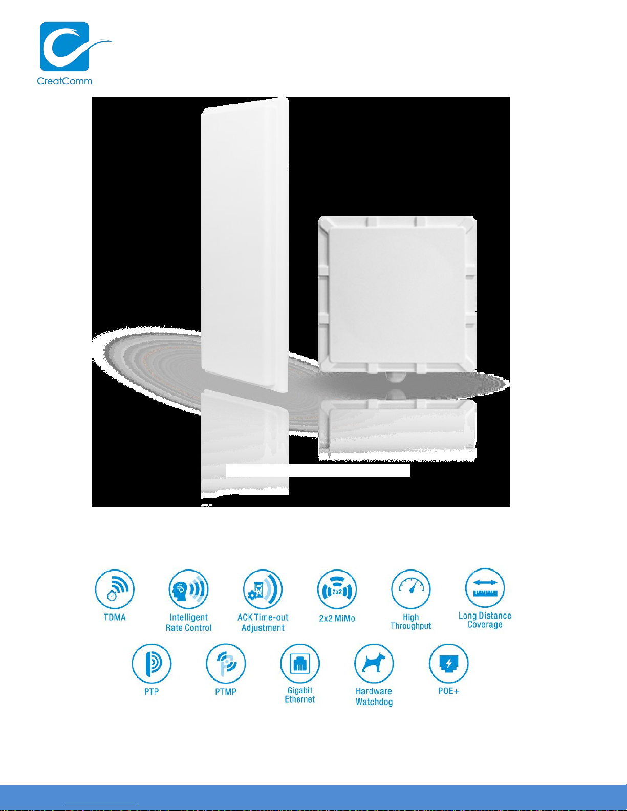
TB5F
802.11a/n 5G O utdoor Wireless AP
Page 2

Page 2
C O PYR IG H T ©2016 C reatC omm Technology
USER MANUAL TB5F
C atalog
V e rs io ns .................................................................................................................. 4
P u rp o s e .................................................................................................................. 4
N o tes....................................................................................................................... 4
D e finitio n s ............................................................................................................... 5
1 P ro d u c t O verview ................................................................................................... 6
1.1 Product Ad vantages ......................................................................................................... 6
1.2 E le c tric al S p e c ific atio n s .................................................................................................... 7
1.3 Features ............................................................................................................................ 9
1.4 U s ing E xam p le .................................................................................................................. 9
1.5 A p p lic a tio n s .................................................................................................................... 10
1.6 H a rd ware O vervie w ........................................................................................................ 10
2 Ins tallatio n ............................................................................................................. 11
2.1 TB 5 F in s ta llatio n ............................................................................................................. 11
2.2 C onnections ................................................................................................................... 13
3 Q uick Configuration .............................................................................................. 13
3.1 Lo g in .............................................................................................................................. 14
3.2 W iza rd ............................................................................................................................. 16
4 TDMA .................................................................................................................... 18
5 S tatus .................................................................................................................... 19
5.1 S tatus .............................................................................................................................. 19
5.2 Monitor ............................................................................................................................ 20
6 W irele s s ................................................................................................................ 21
7 N etwo rk ................................................................................................................. 23
7.1 Router mode ................................................................................................................... 23
7.2 B rid g e m ode ................................................................................................................... 25
7.3 Management ................................................................................................................... 25
7.4 Fire wall ............................................................................................................................ 25
7
.5 IP A lia s e s ......................................................................................................................... 26
7.6 S tatic Ro utes .................................................................................................................. 26
7.7 Tra ffic S h a p in g ................................................................................................................ 26
7.8 VLAN S e tting s ................................................................................................................. 27
Page 3

Page 3
C O PYR IG H T ©2016 C reatC omm Technology
USER MANUAL TB5F
8 Advanced .............................................................................................................. 29
9 S ystem .................................................................................................................. 30
10 Tools ..................................................................................................................... 31
11 AC NMS ................................................................................................................ 34
12 Logout ................................................................................................................... 34
13 Network Configuration Examples ........................................................................ 34
13.1 AP and S tation N etwo rk ................................................................................................. 34
13.2 W D S A P , W DS S tatio n, W D S Repeater Netwo rk ......................................................... 35
13.3 Router Mode ................................................................................................................... 36
FAQ .............................................................................................................................. 37
Page 4

Page 4
C O PYR IG H T ©2016 C reatC omm Technology
V e rs io n
Date
H is to ry
Author
1.0.2589
2016-08-10
C reated
Zhenghu Liu
USER MANUAL TB5F
V e rsio n s
Tab le 1 V e rs io n s
Purpose
This document is proposed for the users of TB5F devices, helping them to configure the
device and list the troubleshooting, so that the devices can be used successfully quickly.
This document mainly contains the following parts: hardware information, web
configuration menu descriptions, network configuration examples, and troubleshooting. It
c a n he lp th e c us to me rs q u ic kly b e familia r with the d e vic e s an d u s e the m c o rre c tly.
N otes
This document is to characterize the TB5F series of devices. Please read the document
c a re fully b e fo re s ettin g up d e v ic e . A n y d a m a g e w h ic h is c a u se d b y in ap p ro p ria te us e w ill
not be covered under the warranty.
Page 5

Page 5
C O PYR IG H T ©2016 C reatC omm Technology
No.
Ite ms
D e s c rip tio n
Outdoor, long distance AP/CPE/Bridge devices by
VTrans is a series of wireless technologies, developed
3
AP
Access point
WIFI station that can be associated to an access
D efinitio ns
USER MANUAL TB5F
Tab le 2 Definition s
1 TB5F
2 VTrans
4 S tatio n (C lient)
5 CPE
C reatC omm Technologies Inc.
and patented by CreatComm, including TDMA,
5M/10M/20M/40MHz bandwidth su p p o rt, intellig e n t
rate c o ntrol, A uto A C K Time-out ad jus t, having the
advantage of long transmission range, high date rate
and robust transmission.
p o int.
C ustomer-premises equipment: it is any te rm in a l and
associated equipment located at
a
su b s c rib e r's premises and connected with
c arrie r's te le c o m m u n ic atio n channel at
a
d e m a rc atio n p o in t.
the
Page 6

Page 6
C O PYR IG H T ©2016 C reatC omm Technology
USER MANUAL TB5F
1 Product Overview
TB 5 F is a p o w e rful W IFI B rid g e / A P / C PE d evic e , w h ic h allo w s W IFI ac c e s s a n d
vid e o /au d io / d a ta trans m is s io n d e v ic e , en a b le s lo n g-range, fast speed and robust wireless
connec tions. Integrated with C reatC o mm’s VTrans technology, TB5F has the advantages
of long-dis tan c e , hig h -throughput, and between point-to-mu lti-p o int p e rform a n c e s .
VTrans technologies include TDMA, 5M/10M/20M/40MHz bandwidth, intelligent rate
c o n tro l, A uto A C K T im e -O ut Adjust and so on. TDMA technology solves the problems of
hid d e n -node problem in the 802.11 network. 5M/10M/20M/40MHz bandwidth can be
fle x ib ly c o nfig u re d b y th e us e s in d iffe re nt wo rkin g s c e na rio to a c h ie ve th e b e s t link q u a lity .
Inte llig en t ra te c o ntro l a lgo rithm c a n b e a d a p ted to q u ic k c han n e l q ua lity varia tio n s
auto m atica lly , thus stabilizing the wireless throughput. AC K Time-O ut Auto Adjust can
automatically detect the distances of the TB5F devices, and thus adjust the wireless
p a ra m e ters to a c h ie ve th e b e s t wire le s s link q uality.
The longest transmission range and max speed of TB5F can be 5 Km and 300Mbps,
ma kin g it s u itab le fo r m a n y a p p lic a tio n s o f W IFI B rid g e / A P / C P E , e s p e c ially ha v e
advantages for point-to -m ulti-p o in t c o m m u n ic a tio n .
1.1 Prod uct A dvantages
The TB5F has the industrial leading technology, owing the performance c a p a b ility o f a
wire le s s b a s e s ta tio n w ith o n ly a s m all fo rm fa c to r, furthe rmo re , it ha s ve ry attrac tiv e lo w
cost.
TB5F has the following advantages compared to the competitors:
1. Embedded VTrans technology
TB5F devices is embedded with VTrans te c hno lo gy, in cluding TDMA, 5/10/20/40MHz
b a nd wid th , inte llig e n t rate c o ntro l, A u to A C K Tim e -out adjust. It makes the device have
longer transmission distance, higher throughput and better point-to-mu lti-p o int
p e rfo rm a n c e.
2. Longer transmission distance, higher throughput
The longest transmission distance of TB5F can be as far as 5 km, and the max throughput
can be 300Mbps,which satisfy the needs of most of the applications.
3. Embedded hardware watchdog
TB5F is embedded with hardware watchdog, which is used to monitor the working status
of the device. Once the system is not working properly, the TB5F device can be rebooted
to guarante e the stab ility of the s ystem.
Page 7

Page 7
C O PYR IG H T ©2016 C reatC omm Technology
Ite ms
S p e c ificatio n s
M o d ula tio n
External 16dBi
Device:212.6*212.6*55mm,
Device:2.8kg
USER MANUAL TB5F
4. Software Ping watchdog function
TB5F software ping watchdog function enable the device periodically ping another device
as s o c ia te d to , s o that it c a n d e te c t if th e s y s te m is wo rking we ll. If th e wire le ss link is lo s t
or there is any problem, the device is rebooted. This is important because the devices can
b e re s to re d to w o rk a u to m atic a lly if th ere is a ny p ro b le m , and avoid the extra human
labour to maintain the outdoor devices.
5. M o re N o n -standard channels availability
Currently most of the WIFI devices are working at standard 802.11 5.8G Hz frequency.
However, standard 802.11 5.8GHz only provide limited channels, and there is serious
interference if there are a lot of 5.8G W IFI devices nearby.
TB5F support more channels near 5.8GHz band, and spread the band to non-standard
frequency part: 4920MHz-6100MHz。The advantage of working at the non-standard
band is to avoid the interference in the standard channels, and the wireless throughput
can be improved.
N o te:
Please confirm whether those non-stand ard c h a n ne ls are p e rmitte d lo c ally b e fo re
using them.
6. O utdoor industrial product
TB5F device can work at all kinds of outdoor s e v e re e n viro nm e nts, inc lud in g -30 to 70
degree temperature, 5% to 95% humidity, while maintain good performance.
1.2 Ele c tric al S p e c ific atio n s
The e le c tric a l s p e c ific a tio n s are s h o w n are th e follo win g tab le :
Tab le 3 E le c tric a l S p e c ific ation s
Standard IEEE802.11 a/n(2T2R 300Mbps)
O pe ra tio n
Frequency
W irele s s
Mode
Antenna
5.745~5.825 GHz(More Non-standard channels is
availa b ility,49 2 0 M H z-6100MHz)
802.11 a/n: O FDM
H:90° V:12°
Antenna size
W eigh t
ANT:450*140*35mm
AN T:1.26kg
Page 8

Page 8
C O PYR IG H T ©2016 C reatC omm Technology
O utput power
30dBm
Receive
11n:13.5/15/27/30/40.5/45/54/60/81/90/108/120/121.5/135
11a :54/48/36/24/18/12/9/6Mbps(adaptive)
D is tanc e
Outdoor open area: < 5 km
Power supply
802.3at PoE+
Inte rfa c e
PoE
O pe ra tio n
S to rage
O pe ra tio n
E nc ryp tio n
802.x/WPA-PSK/WPA2-PSK
N etw o rk
R o ute r/B rid ge
O pe ra tio n
S e c u rity
MAC/IP filte r, SSID hidden
N etw o rk
Supported (Avoid 802.11 hidden-node problems, and improve
Auto ACK
Management
Web based
Firmware
Bandwidth
USER MANUAL TB5F
S e ns itivity
Date rate
H ard w a re
Temperature
Temperature
H u m id ity
Mode
-72dBm@65Mbps, -94dBm@6Mpbs
/150/162/180/216/240/270/300Mbps(HT40)
130/117/104/78/65/58.5/52/39/26/19.5/13/6.5Mbps(HT20)
-30℃~+70℃
-40℃~+85℃
5%~95%RH
AP /S tation/W D S A P /W DS S tation/W D S R epeate r
protocol
S o ftw a re
TDMA
tim ing A d ju s t
and Logs
C on figu ra tio n
Update
supported
TCP/UDP/ARP/ICMP/DHCP/HTTP/NTP
the point-to-m ulti-po int p e rfo rmance)
S up p o rted
NTP, SNMP, S ys lo g, Telnet
S up p o rted
S up p o rted
5M/10M/20M/40MHz
Page 9

Page 9
C O PYR IG H T ©2016 C reatC omm Technology
USER MANUAL TB5F
1.3 Features
High performance 802.11n 2×2 MIMO chip
Max transmission range: 5Km, and max transmission throughput: 300Mbps
Inte g rated VTrans tec hn o lo g y , in c lu d in g T D M A , in te llig e n t ra te c o n tro l, A u to A C K
Tim e -out adjust
TDMA solves the problems of hidden-node problem in the 802.11 network, thus
having better long-distance and PTMP performance
Support five operation modes: Access Point, Station, W DS A ccess P o int, W DS
Station, WDS Repeater
Support point-to-p o int, p o in t-to-m u ltip o int c o n n e c tio n
Unique RF and antenna design enables long-range transmission
W ire le s s m ultim e d ia o p timizatio n te c h n o lo g y g u a ran te e s v id e o / aud io trans m is s io n
QoS
Web ba s e d w o rkin g s c e na rio s e le c tio n m ake s th e in s ta llation a nd s e tting m u c h
easier
Reliable PoE power supply, support 802.3af standard
Web-based configuration, easy to use
Waterproof housing and accessory kit protects
1.4 U s in g E xa m p le
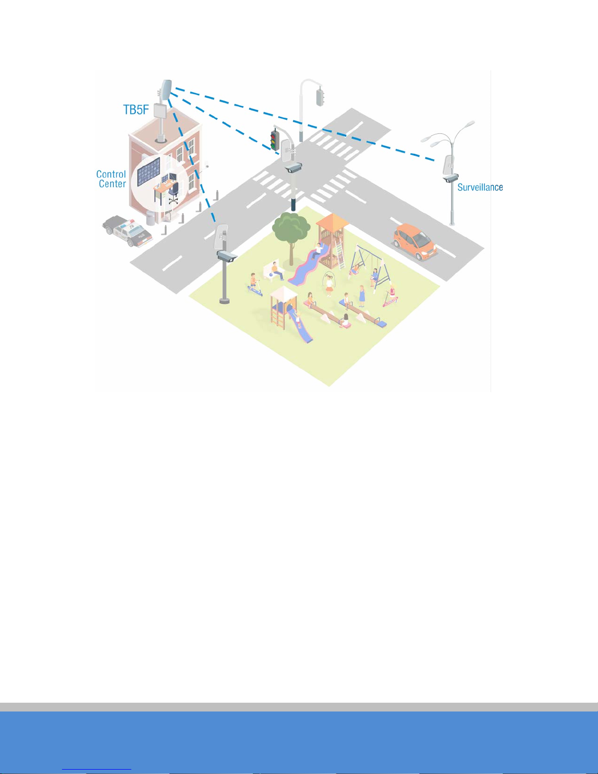
The TB5F usage example are shown in Figure 1, it can be used as W IFI AP, C PE, or
o u td o o r P T P , P T M P to p o lo gy. T h e re fo re , TB 5 F is su itab le fo r v a rio us ap p lic a tio ns like
wire le s s vid e o tra n sm iss io n , and wire le s s s ig n al c o ve ra g e .
Page 10
Page 10
C O PYR IG H T ©2016 C reatC omm Technology
USER MANUAL TB5F
Fig ure 1 TB5F using examples
1.5 Ap p lic atio n s
TB 5 F c an b e us e d wid e ly in the fo llo wing ap p lic a tio ns :
W ireles s vid e o s urv e illan c e (free -way, c ity, p o lic e , o il p ip e line , fo re s t and etc . )
C arrier wireles s b ac khaul and ru ra l area inte rn e t last-m ile w irele ss so lutio n
Enterprise local area netwo rk inter-connection
W IFI sig n al c o v e ra g e a nd ru ra l wire le s s c o ve rag e
1.6 Hardware O verview
TB 5 F ’s h ard w a re in fo rm atio n is d e sc rib e d in th e fo llo win g Ta b le 4 :
Page 11

Page 11
C O PYR IG H T ©2016 C reatC omm Technology
H a rd w a re S p e c ific a tio ns
C PU /Baseband Radio
Atheros AR9344
M e mo ry
64MB DRAM, 8MB Flash
P hys ic a l Inte rfa c e
1×10/100/1000M Base-TX (C at. 5/5E,
Power supply
802.3at PoE+
USER MANUAL TB5F
Tab le 4 H ard ware info rmatio n
RJ-45) Ports
2 Ins ta llatio n
This c h ap te r d e s c rib e s ho w to in stall TB 5 F d e v ic e in the b rid g e m o d e , an d the in s tallatio n
method of router mode can be seen in C hapter 7.
2.1 TB 5 F ins tallatio n
TB5F is an outdoor product, and it has the aluminium shell, has the IP67 water-proof
capability, and can operate at -30℃~+7 0 ℃ tem p e ratu re .
To m a ke TB 5 F w o rk w e ll in all kind s o f co m p lic a te d o utd o o r e nviro nm e n t, th e in s ta llation is
very im p o rta n t. If it’s n o t ins ta lle d we ll, th e wire le ss lin k q u a lity w ill b e affec te d , and the
lo n g -term wo rking stab ility c ann o t b e g u ara n te e too .
Package c o ntents :
O pen the package carefully, and make sure that none of the fo llo wing ite m s lis te d a re
mis sin g :
O ne TB5F device
O ne 802.3at PoE+ power adapter
O ne RJ45 water-proof connector
O ne antenna
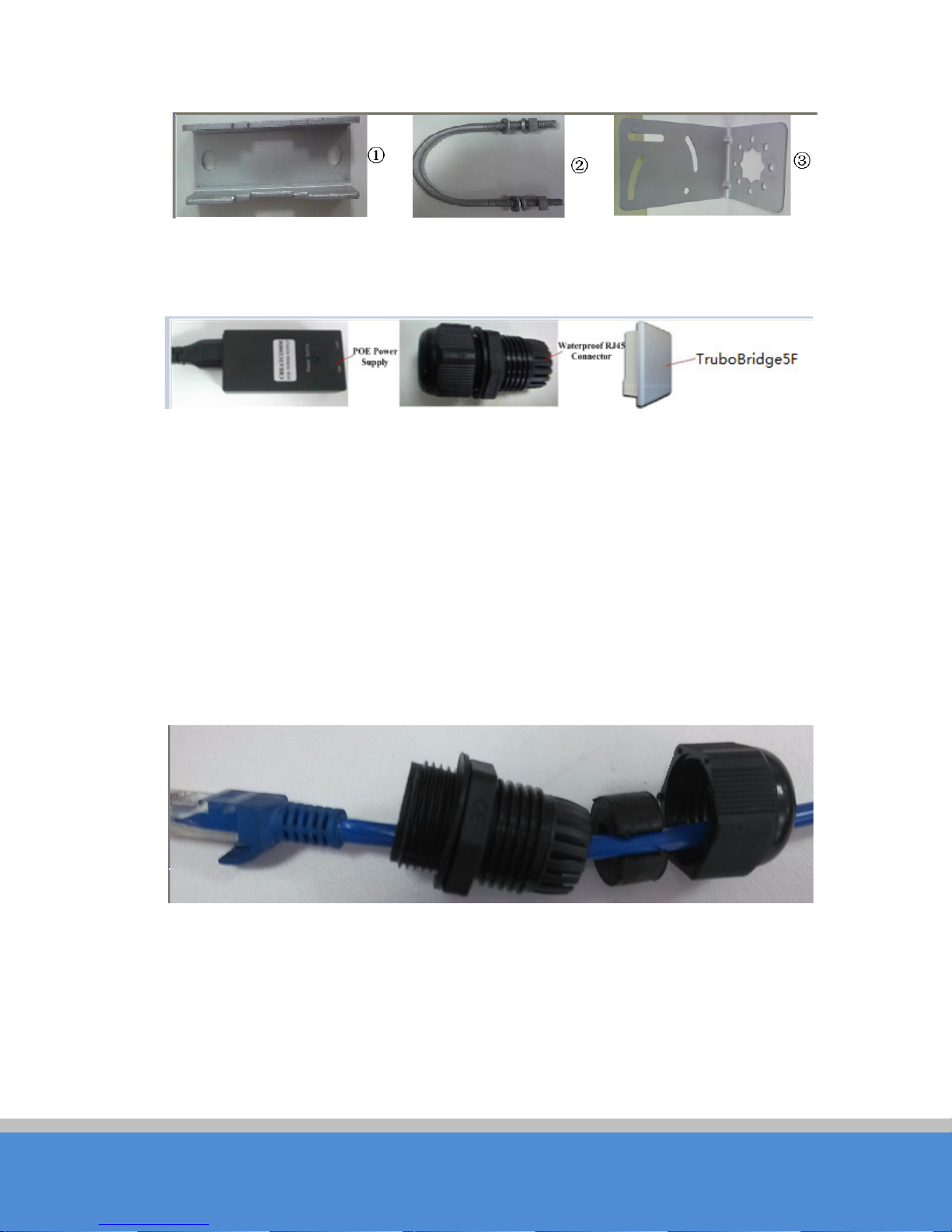
Metal Mast-Mount Set, shown in Figure 2, and this set contains 3 components.
O ne quick user manual
Page 12
Page 12
C O PYR IG H T ©2016 C reatC omm Technology
Fig ure 2 Metal Mast-Mount S ets
All the components in the package are shown in Figure 3:
Fig ure 3 Package contents
USER MANUAL TB5F
Ins talla tio n s tep s :
Ins talla tio n o f TB 5 F c an fo llo w the b e lo w s te p s :
1. Take all the c o ntents from the package
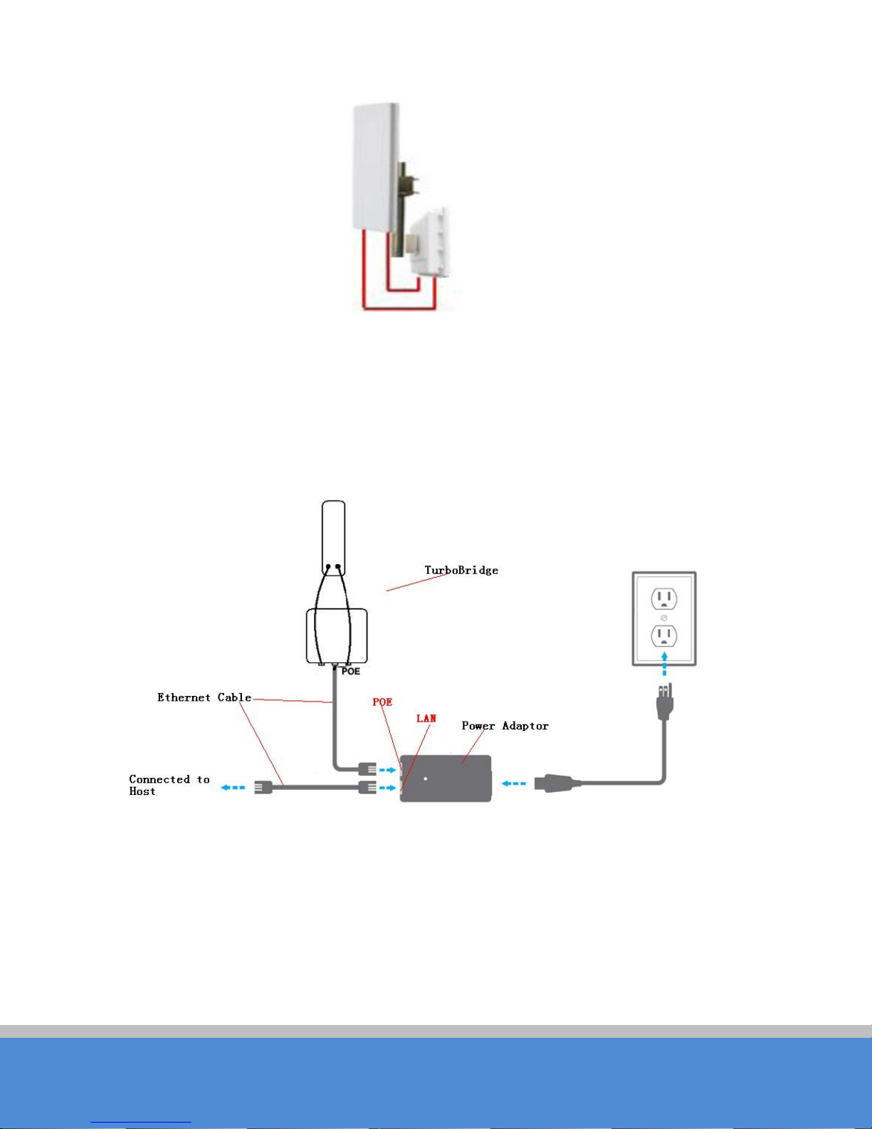
2. Mount TB5F in a mast, and then fix the device on the mast as shown in Figure 5.
3. After the TB5F is fixed on the mast, protect the Ethernet cable using the water-p ro o f
connector.
Fig ure 4 W ater-proof connector and the Ethernet cable
4. Screw the water-proof connector well on the TB5F shell.
Page 13
Page 13
C O PYR IG H T ©2016 C reatC omm Technology
USER MANUAL TB5F
F ig u re 5 TB5F installations on a mast
2.2 Connections
The connection of TB5F device to PoE and power supply is shown in Figure 6. TB5F has
1 RJ45 ports, and please connect the device with the PoE power adaptor as shown in the
Fig ure .
3 Q uick C onfiguration
This chapter describe how to configure the device quickly.
Fig ure 6 C onne c tio n s a t B rid g e m o d e
Page 14
Page 14
C O PYR IG H T ©2016 C reatC omm Technology
USER MANUAL TB5F
3.1 Lo g in
To log in the TB5F device, user needs to configure the TC P/IP of your co m p ute r firs t as
th e fo llo w in g s te p s :
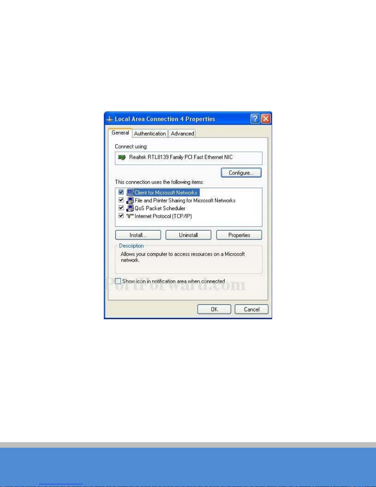
1.R ig h t c lic k L o c a l A re a C on n ec tio n ic o n o f y o u r c o m p u te r a n d c lic k p ro p e rtie s , th e n
c lic k C ontinue , the Lo c a l A rea C on n ec tion P ro p e rtie s d ia lo g b o x ap p e a rs as F ig u re 7.
Fig ure 7 Local Area C onnec tio n P ro p e rtie s
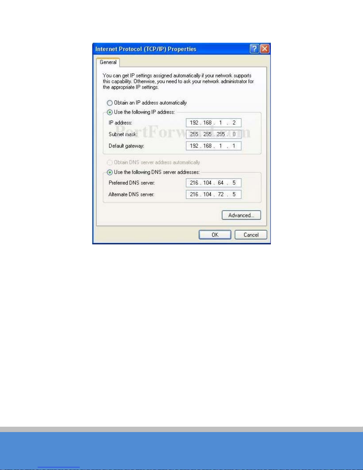
2.S e le c t Inte rne t P ro to c o l (TC P/IP ) and c lic k P ro p e rties b u tto n , a n d th e fo llo win g d ialo g
box appears:
Page 15
Page 15
C O PYR IG H T ©2016 C reatC omm Technology
USER MANUAL TB5F
Fig ure 8 IP settings
3.In the above Figure 8, IP address should be set to 192.168.1.*, here * can be a
numb e r between 1-255 (but not 36) since the TB5F default IP address is 192.168.1.36.
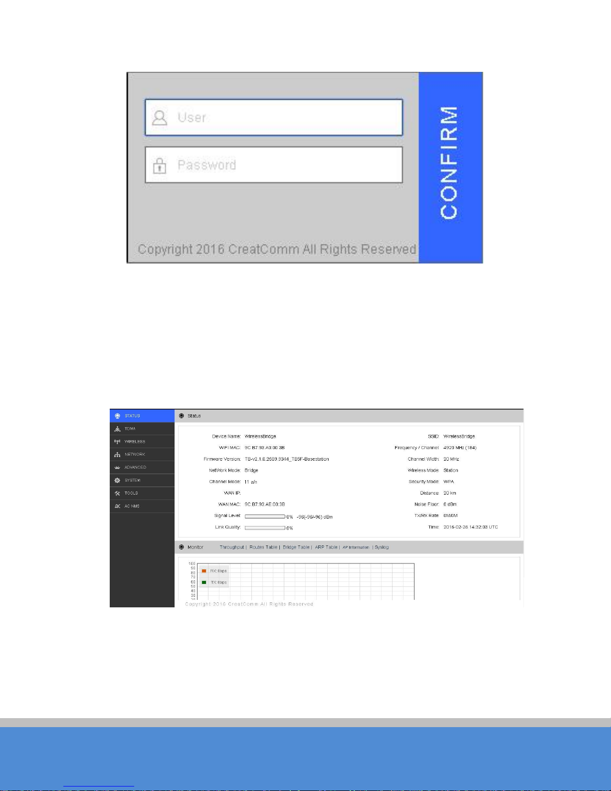
4.When the above IP setting is done, input the default IP 192.168.1.36 into the address
bar of your web browser, and the following log in interface appears as shown in Figure 9.
5.In F ig u re 9, in p u t th e u s e r nam e an d p a s s w o rd (d e fa u lt is ad m in / ad m in ), c lic k C o n firm ,
then you can log in to the web configuration menu of the TB5F device.
Page 16
Page 16
C O PYR IG H T ©2016 C reatC omm Technology
3.2 W iza rd
USER MANUAL TB5F
Fig ure 9 Lo g in in te rfa c e
The users will see how to configure the TB 5F d e vic e q u ic kly in this c h a p ter.
1.The firs t p a g e s ho wn a fte r lo g in is the S tatus page, which indicates the working status,
current setting, software version and other information of the TB5F device. User can
sw itc h to o ther p a g e s b y c lic kin g th e le ft main menus in Figure 10.
Fig ure 10 Status Page
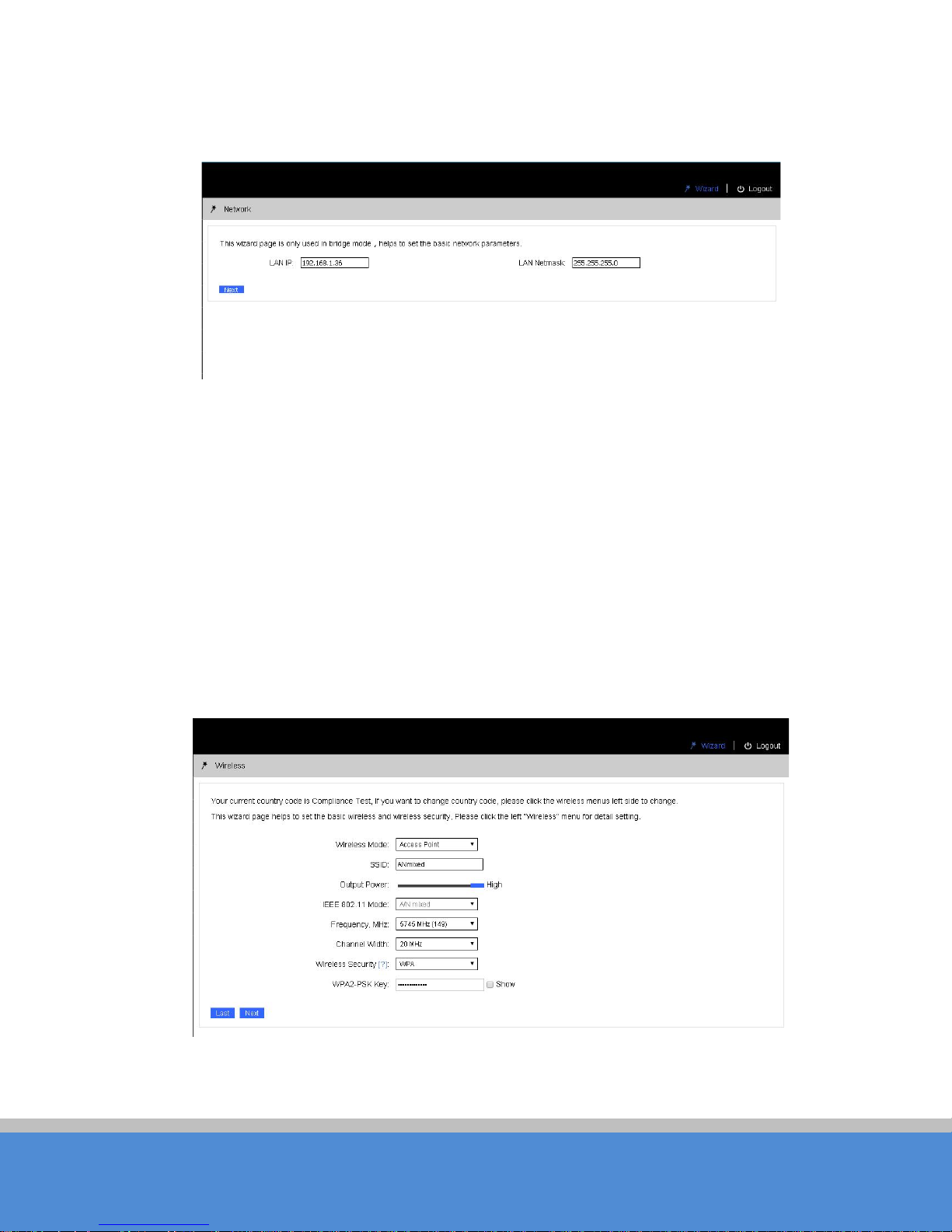
2.C lick W izard in the top right corner, the page goes to W izard -N e two rk page as shown
in Figure 11, and this page helps to set the basic network parameters. The default mode
is Bridge mode, and the default LAN IP address is 192.168.1.36. If the user wants to
configure the device to Router mode, please click N e two rk in the m ain menu.
Page 17
Page 17
C O PYR IG H T ©2016 C reatC omm Technology
N o te:
If several TB5F devices are connected in the Point-to-Point or Point-to-M ulti-P o int
USER MANUAL TB5F
to p o lo gie s, they m us t b e c o nfig ure d to d iffe re nt IP a d d res s to a v o id c o llisio ns .
Fig ure 11 W iza rd -N e two rk
3.After finishing the W iza rd-N e twork settings, clic k next and it go es to W iza rd -W ire le s s
page shown in Figure 12. The most used wireless modes a re Access Point and Station.
S tation mo de: The device acts as a W IFI station, and it can be connected to a normal
home access point or TB5F access point.
Access Point mode: The TB5F device acts as an access point, which allows normal W IFI
statio n s ac c e s s . F o r d e ta il s e tting s o f w irele s s m o d e , p le as e c lic k Wireless in the main
menu.
N o te:
If two TB5F devices need to be connected in p o in t-to-point topology, one of the
device need to be configured as Access Point, and the other one need to be configured
as S tation, and b oth of them should have the same E nc ryp tion method.
Fig ure 12 W iza rd -W ire le s s
Page 18
Page 18
C O PYR IG H T ©2016 C reatC omm Technology
USER MANUAL TB5F
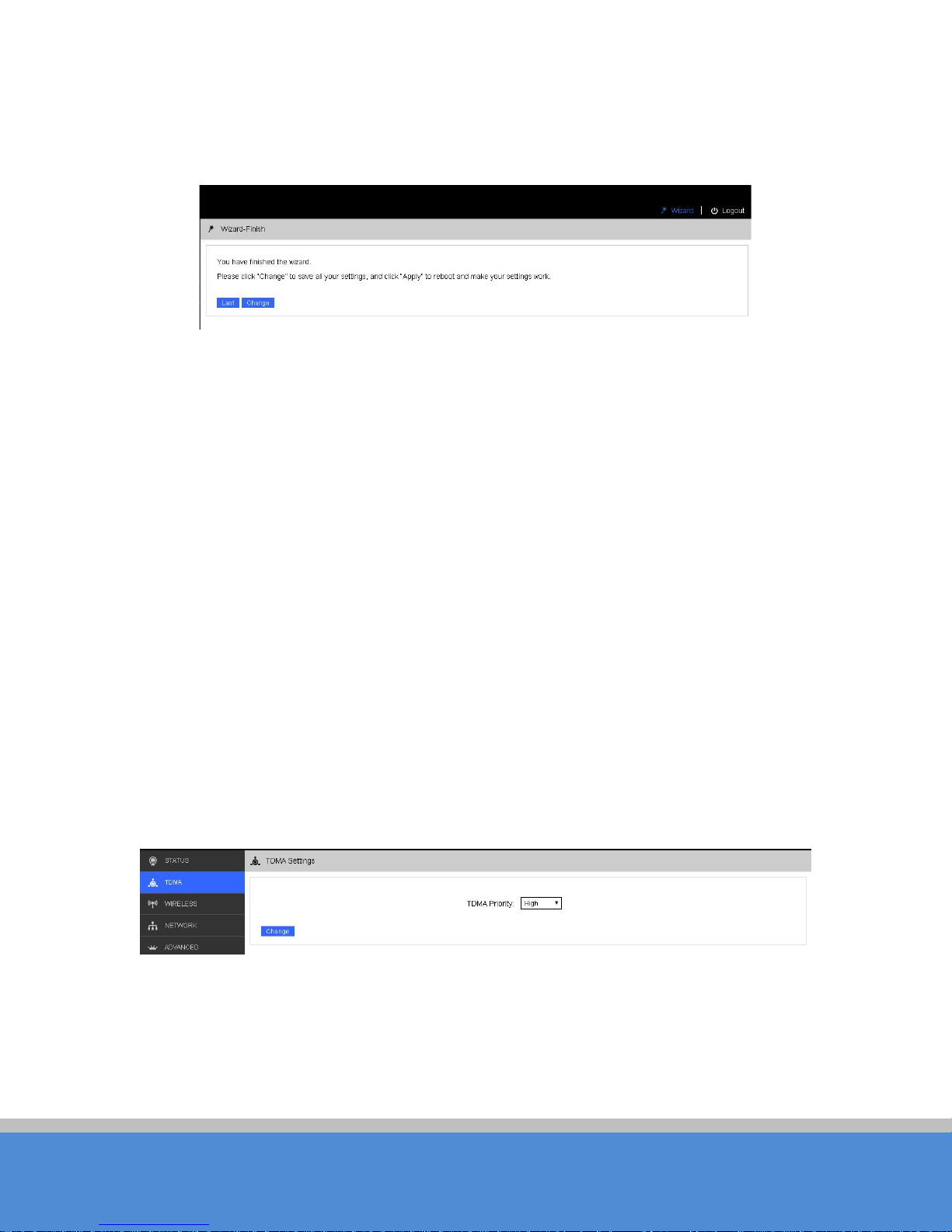
3.C lick “N e x t”, th e la s t p a ge o f W iza rd is s ho wn in Fig ure 1 3 . U s e r c a n c lic k C hange to
sa v e all the s e ttin g s , a nd th e n c lic k Apply the make the setting effective, or click Last to
modify the p revious settings.
Fig ure 13 W iza rd -F inis h
4 TDMA
Currently, most of the outdoor bridge products are developed based on 802.11 protocols,
ho we v e r, it has the lim itatio n s o f s h o rt-distance, hidden node problems, and poor point-to mu lti-p o int p e rform a n c e .
The VTrans technology developed and patented by C re a tC om m , utilizing a s e ries o f
advanced technologies such as TDMA, 5M/10M/20M/40MHz bandwidth support,
inte llig en t ra te c o ntro l, A u to A C K Tim e -out Adjust, having the advantage of long
transmission range, high date rate and robust transmission.
TDMA technology solves the problems of hidden-node problem in the 802.11 network
infra -structure. 5M/10M/20M/40MHz bandwidth can be flexibly configured by the uses in
d iffe rent wo rkin g s c en a rio to a c h ie ve the b e s t link q u ality . In te llig e nt rate c o ntro l a lgo rithm
c a n b e a d a p te d to q u ic k c h an n e l q ua lity varia tio n s, w h ile s ta b iliz e th e w irele ss th ro u gh p u t,
thus suitable for long-d istanc e tran s m is s io n . A C K T im e -out Auto Adjust c an auto matically
detect the distances of the TB5F devices, and adjust the wireless parameters to achieve
th e b e s t link q u a lity .
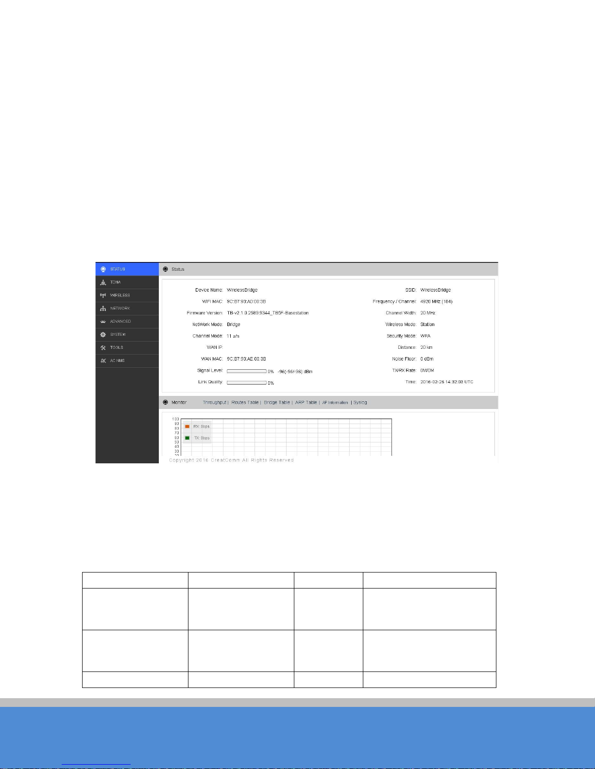
The TDMA setting is shown in the following Figure 14.
Fig ure 14 TDMA s e tting
To use the TDMA, the user needs to enable TDMA mode in the AP device, and set a
p rio rity le v e l in the s ta tio n d e vic e . When several stations are connected to one AP, different
stations demand different throughput. If the station demands higher throughput, its priority
Page 19
Page 19
C O PYR IG H T ©2016 C reatC omm Technology
Ite ms
D e s c rip tio n
Ite ms
D e s c rip tio n
D e v ic e
N ame o f the
W IFI M A C
W IFI M A C of th is d e vic e
Firmware Version
Software version
C hannel
W irele s s c o m m u nic atio n
W AN IP
WAN IP address
WAN MAC
MAC of the WAN port
USER MANUAL TB5F
level can be set to High, otherwise set to Low. When the stations demand the same
throughput, their priority level can be set to the same level.
N o te:
When using TDMA mode, the TDMA button need to be enabled at both AP and
statio n d e vic e s in th e w e b -based configuration menu. The devices from other vendors
cannot be connected to TB5F in the TDMA mode.
5 S tatus
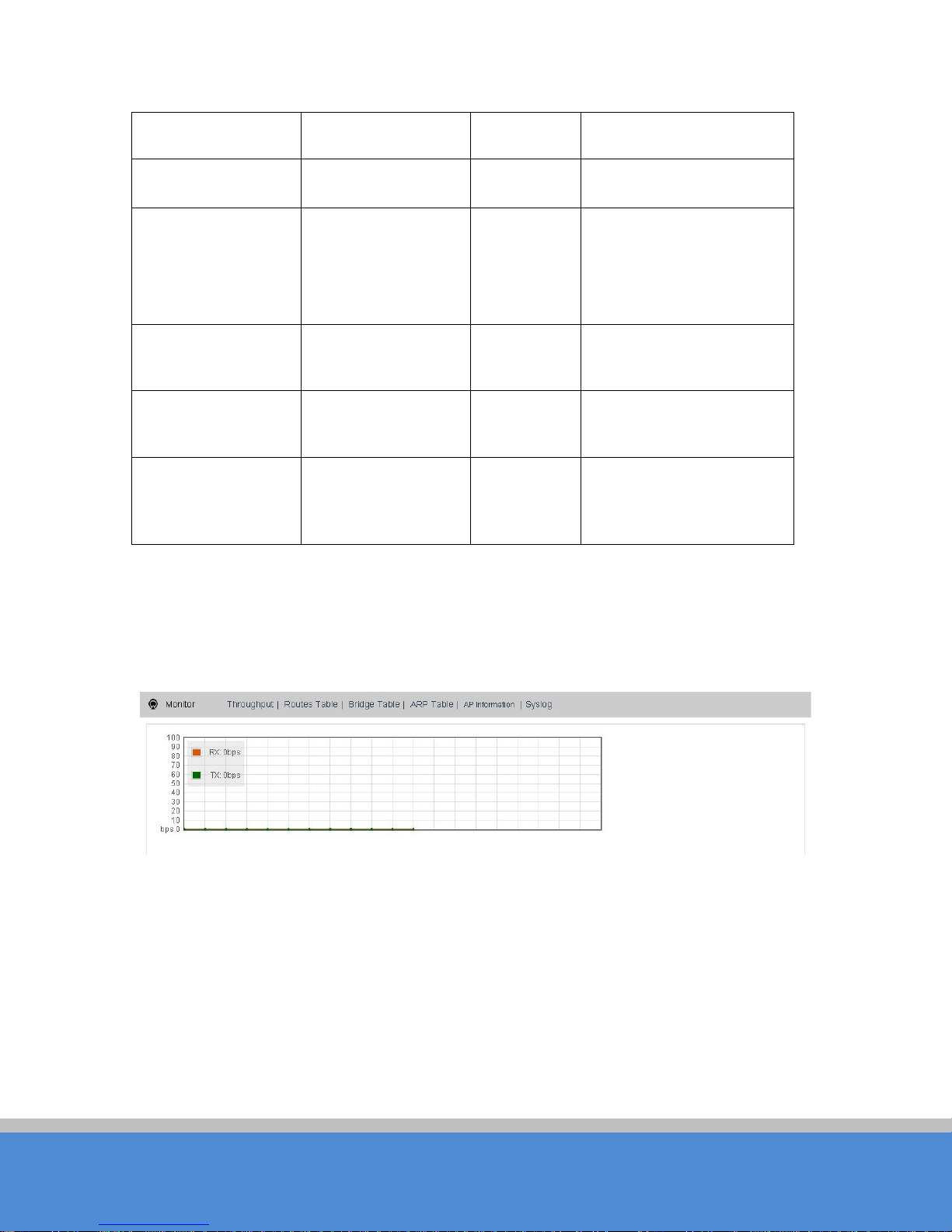
S tatus is the first page shown after logging in. It shows the current configuration and realtim e m o nito ring o f the d e vic e , s e e n in th e fo llo w in g F ig u re 1 5. T h is p ag e is d iv id e d into 2
p arts : S tatus and Monitor.
5.1 Status
All the configurations in Status page is shown in Table 5.
Fig ure 15 S tatus
Tab le 5 Configurations shown in S tatus
device , for
example: TB5F
number
mode
protocol, for example,
802.11b/g/n
Page 20
Page 20
C O PYR IG H T ©2016 C reatC omm Technology
N etw o rk M o de
Network mode:
SSID
The name of the wireless
Frequency/C hannel
W irele s s c han n e l
C hannel
W irele s s M o d e
Access P o in t,
S e c u rity
W irele s s e n c ryp tio n
D is tanc e
The distance
Noise Floor
N o is e F lo o r va lu e
S ig nal le vel
It indicates the
Link Q ua lity
Q ua lity o f th e c o nn e c tio n
TX/RX R ate
The date rate of
Tim e
The real-tim e
USER MANUAL TB5F
5.2 Monitor
R o ute r or B rid g e
chosen
S tation,
WDS Station,
WDS Access Po int,
WDS R epeater
between two
associated devices
signal strength of
the device
c u rre n t de vic e
during sending and
re c e iving d a ta .
W idth
netwo rk
5M、10M、20M、
20/40M AUTO
method
link
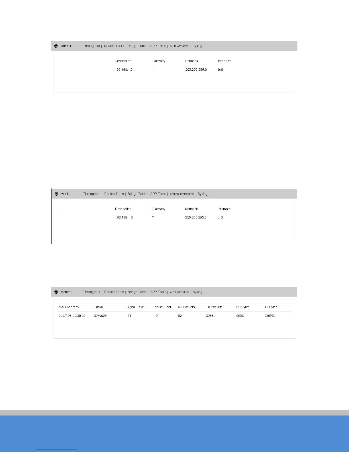
Throughput: The figure here monitors the real-time throughput of the wireless link, shown
in th e follo w in g F ig u re 1 6 .
Fig ure 16 Throughput monitor
Route Table: It is stored in a router that lists the route s to p articular network destinations,
and in some cases, metrics (distances) associated with those routes. The route table
c o n tain s info rm atio n ab o u t the to p o lo g y o f the ne two rk im m e d ia te ly a ro u n d it.
Page 21
Page 21
C O PYR IG H T ©2016 C reatC omm Technology
USER MANUAL TB5F
Fig ure 17 R o ute tab le
B rid g e T a b le : It lis ts a ll the d e vic e s th at c o m m u nicate through the TB5F device.
ARP Table: It lists the IP address and MAC address of the devices that communicate
through the LAN port of the TB5F device.
A P / S tatio n Info rm atio n : Showing the status information of the associated devices.
Fo r e xam p le , if the TB5F device is an AP, and the associated device is a Station, and this
Station Information shows the related information of the Station device in the Figure 18.
Fig ure 18 STA Information of an AP
If the TB5F is a Station, and AP Information shows the associated AP device’s information,
seen in Figure19.
Fig ure 19 AP Information o f a S tation
6 W irele s s
W irele ss is s h o w n in F ig ure 2 0.
Page 22
Page 22
C O PYR IG H T ©2016 C reatC omm Technology
USER MANUAL TB5F
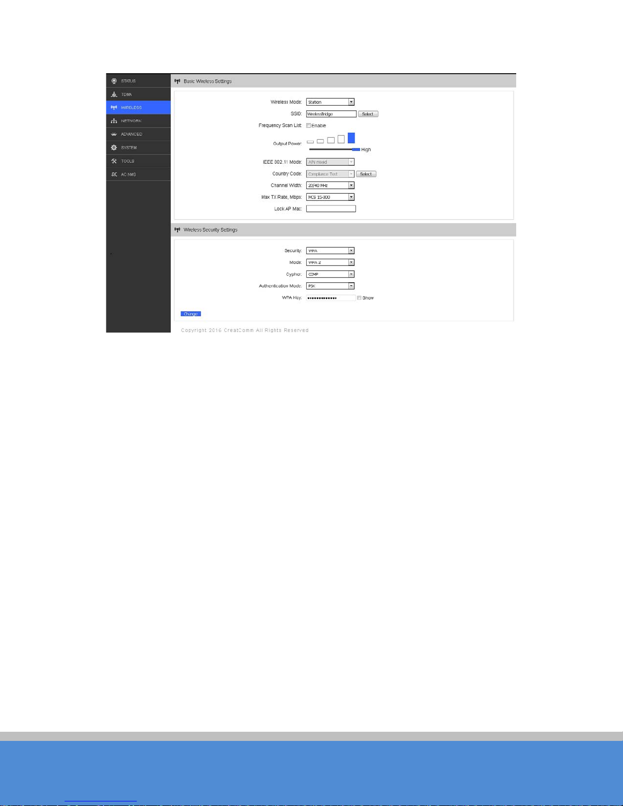
Fig ure 20 Wireless
W irele s s M o d e : There are totally 5 wire le s s m o d e s , in c lu d ing : S tatio n , A c c e s s P oin t, W D S
Station, WDS Access Point and WDS Repeater.
Access Point: Access point.
S tation (or C lient): A client device that c an c o nnect to an AP.
W D S S tation: U s e W D S fe a ture to lin k m ultip le A P s in a n e two rk, all associated stations
from any AP can communicate with each other like in ad-hoc mode. WDS station means
th is d e v ic e is a s ta tio n in W D S mo d e.
WDS AP: U se W DS feature to lin k m u ltip le A P s in a n e two rk, a ll a ss o c ia te d s tatio n s fro m
any AP can communicate with e a c h o the r like in a d -hoc mode. W DS AP means this
d e vic e is an A P in W D S m o d e .
WDS Repeater: A TB5F device can be configured to WDS Repeater mode, so that it can
connec ted to ano the r W D S S tation or W D S R epeater.
SSID: Name of a wireless.
Shown in Figure 20, the user can click the Select button to lis t all the S S IDs that can b e
associated, and then choose the one need to be associated.
Frequency MHz: This only appears when the device is configured to Access Point mode
or WDS Access Point mode. The device can only work on one channel at the same time.
Page 23

Page 23
C O PYR IG H T ©2016 C reatC omm Technology
USER MANUAL TB5F
Frequency Scan List: This only appears when the device is configured to Station mode or
WDS Station mode. If it’s not enabled, the station will scan all the channels which both the
device and the country code allowed and then choose the same channel as the
as s o c ia te d A P . If it’s e nab le d , c lic k se le c t, a no th e r w ind o w will p o p u p and le t th e u s e r to
choose the working channels, and the channels should include the associated AP’s
channel, which can fasten the association process between the AP and the Station
O utput P o wer: O utput power of the device.
C ountry C ode: Different countries allows different channels, use can choose the country
c o d e to o nly a llo w the d e vic e w o rks at the c h ann e ls p e rm itte d in the p a rtic ular co untry.
C hannel W idth: C hannel width selection, and TB5F device supports
5MHz/10MHz/20MHz/40MHz bandwidth.
Max TX R ate: M a x tran s m is s io n rate , and it ca n b e u s e d to lim it the m a x tran s m is s io n rate
of a device.
Lock AP MAC : In S tation, W D S S tation, and W DS Repeater modes, users can use this to
limit th e A P s a s s o c ia te d to .
S e c u rity: User can set the security based on needs to guarantee the wireless security.
WPA: Encryption method supported by 802.11 Protocols.
7 N etwork
7.1 Router mode
TB5F acts as a router when configured to Router mode. In router mode, the connection is
shown in Figure 21. User needs to connect the PoE port of PoE adaptor to the PoE port of
the TB5F.
After the above connection, the TB5F can work as a router. The LAN port of PoE adaptor
ac ts as the W A N p o rt of the router.
Page 24

Page 24
C O PYR IG H T ©2016 C reatC omm Technology
USER MANUAL TB5F
Fig ure 21 Connection figure of router mode
The Network page is shown in Figure 22.
Fig ure 22 N etw o rk-Router mode
WAN Mode: WAN mode can be configured to DH C P , S tatic IP or PPP oE. W hen s et to
DHC P, the device can dynamically get the IP address. W hen set to Static IP, user needs
to manually set the IP add ress, N etmask, G ateway IP and o ther information.
W AN IP : WAN IP address. It should be set to the same segment of IP address of the
inte rn e t p ro v id e d b y IS P , p le as e c he c k w ith the IS P fo r th is info rm a tio n .
WAN Netmask: WAN Net mask, use can check with the ISP for this information.
N o te : W AN IP address should not be the same as the IP devices of the internet to a vo id
c o llisio n .
Page 25
Page 25
C O PYR IG H T ©2016 C reatC omm Technology
USER MANUAL TB5F
LA N IP : LAN IP address.
LAN Net mask: LAN Net m a s k info rm atio n .
P rim a ry D N S and S ec o n d ary D N S : Please check with the ISP for the information.
7.2 Bridge mode
In Bridge mode, there is no WAN port. The LAN port of the PoE adaptor, and the LAN2
port of the TB5F device can all be the LAN port, and the user can choose one of them to
use as LAN port. Please refer to Figure 6 for the connections in Bridge mode, and the IP
address/Netmask information setting is the same as Router mode.
7.3 Management
The IP address of the device can be modified, and the management of the device can be
performed by setting the specified management interface.
7.4 Fire w all
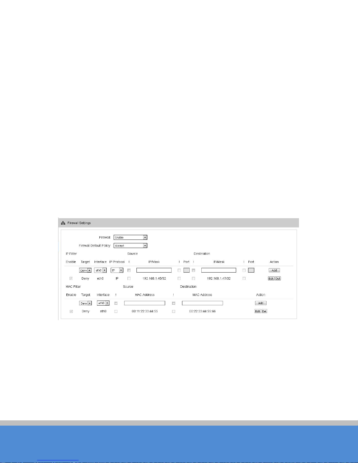
W hen the fire w all is e na b le d , th e d evic e c a n allo w o nly s o m e d e vic e s to b e a s s o c ia te d to .
Shown in Figure 23, and there are 4 cases of Firewall filtering.
Fig ure 23 F ire w a ll
1. Accept one or several devices with particular MAC address.
2. Deny one or several devices with particular MAC address.
3. Accept one or several devices with particular IP address.
4. Deny one or several devices with particular IP address.
Page 26
Page 26
C O PYR IG H T ©2016 C reatC omm Technology
USER MANUAL TB5F
7.5 IP A lia s e s
Add multiple IP to a network interfac e .
7.6 Static Routes
This feature can be set to static routing.
7.7 Traffic Shaping
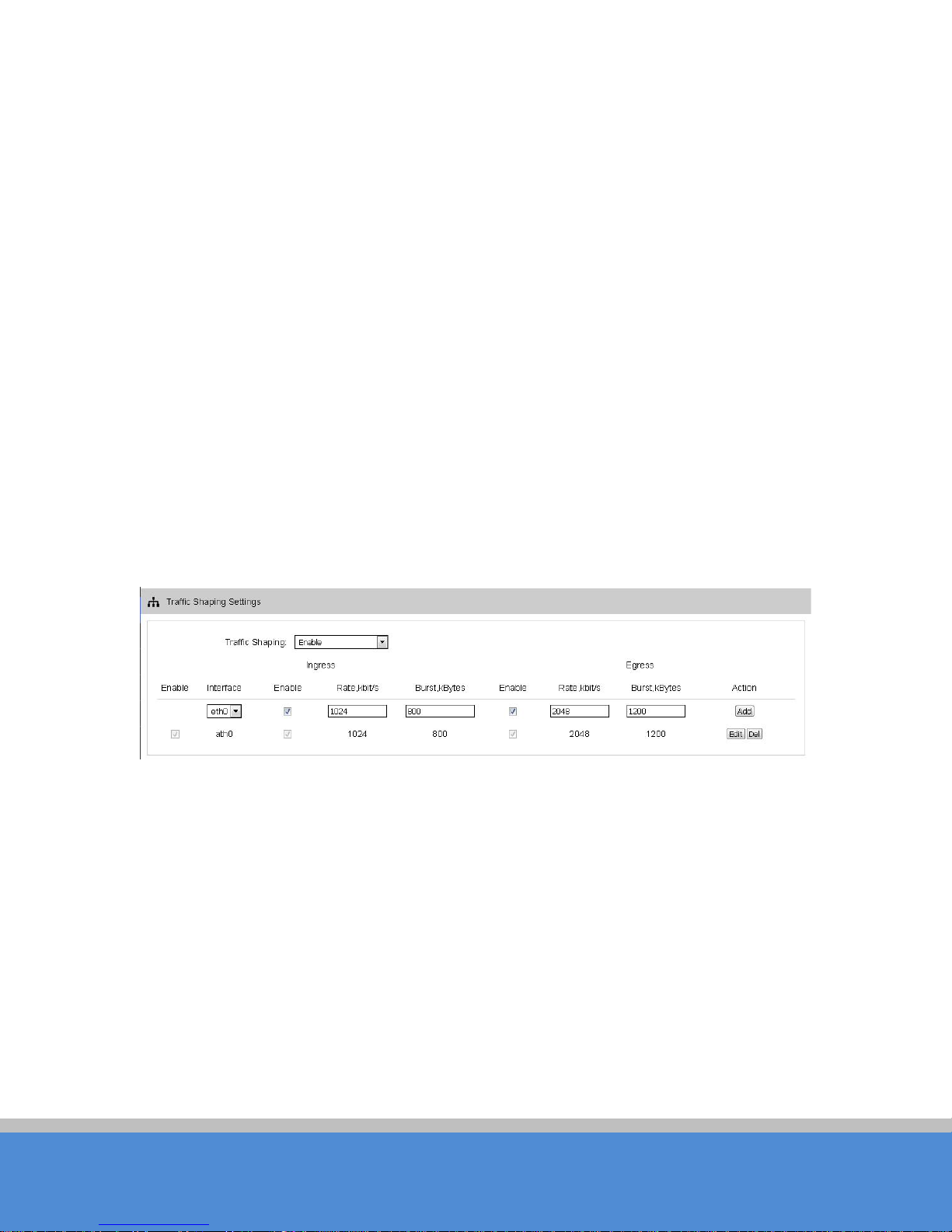
Traffic shaping is used to control the traffic of ingress/egress based on each network port.
As shown in figure 24, the ingress of ath0 is lim ited to 1 0 2 4 K b p s , and the e g re s s is lim ited
to 2048Kbps. That means the receiving rate of the wireless link is limite d within 1 M b p s ,
th e s en d in g ra te is lim ited to le s s th an 2 M b p s . B ut usu a lly, th e inp ut limited e ffec t is no t
o b v io u s ly, th a t’s b e c a u s e w e c o uld no t c o n tro l ho w q u ic kly th e traffic a rrive s . H o w e ve r,
when a port sends out egress traffic, it can control how q uic kly the traffic e x its .
Burst defines the how many bytes allowed for downloading/uploading during a quick time.
That leads to momentary throughput can greater than the limit value.
Fig ure 24 Traffic S hap ing
Ing re s s tra ffic e n te ring ath0 , contro l the inp u t rate
E g re s s traffic e xitin g ath 0, c o n trol the o utput rate
The relationship of rate and burst for ingress:
S e t b urst to 0 , the rate of ingress is unlimited
S e t b urst to ab o ut 1/1 0 of rate limit, the rate curve is stab le
S e t b urst larger than rate limit, the rate curve will hold a high value for a while then down to
sta b le
Below is the table that reflects the relationship between ingress rate limit and burst.
Page 27
Page 27
C O PYR IG H T ©2016 C reatC omm Technology
Ingre ss
Throughput when reach stable
Mbps
10000
10
4.286
S ta b le
Hold on 10 seconds at 29.6, then
suddenly down to s tab le
E g re s s
Throughput when reach stable
20000
200
19.205
S ta b le
Hold on 20 seconds at 24.5, then
H o ld o n s eve ral minu tes a t 2 4 .5,
USER MANUAL TB5F
R ate Lim it(kb p s ) Burst(kB ytes)
(
D es c riptio n
)
10000 0 29.587 U nlim ite d
10000 100 8.037 Oblique up to stable
10000 1000 8.825 From 9.5 do wn to stable
10000 10000 8.6 From 28.5 down to stable
10000 40000 8.6
The relationship o f rate and b u rs t fo r egre s s :
S e t b urst less th an 1 /10 of rate limit, the rate c urve is stab le totally
Set burst larger than rate limit, the rate curve will hold a while at a higher value then down to
sta b le
B e lo w is the table that reflects the relationship between egress rate limit and burst.
R ate Lim it(kb p s ) Burst(Kb ytes)
(Mbps
)
D es c riptio n
20000 0 18.853 S tab le
20000 20 19.021 S tab le
20000 2000 19.437 From 23.5 down to s table
20000 20000 19.2
20000 80000 19.2
suddenly down to stable
then suddenly down to stable
7.8 VLAN Settings
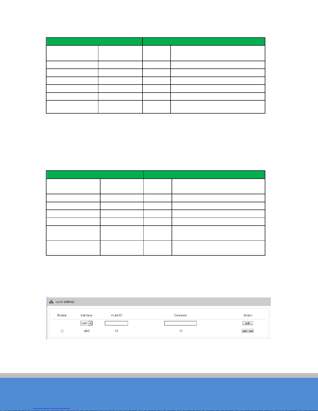
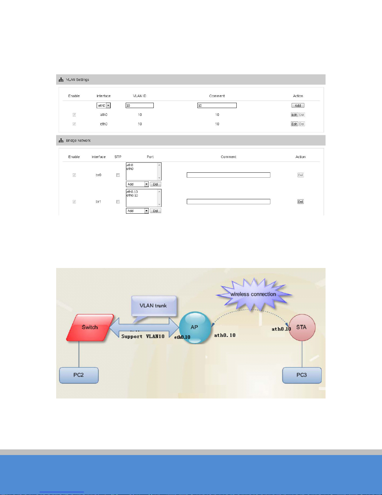
The V L A N fu n c tio n allo ws u s e r to c re ate m ultip le virtual lo c a l are a n e tw o rk. A s s h o w n in
figure 25, we add a VLAN on port ath0. The VLAN ID is 10. The range of VLAN ID is
2~4094. Each VLAN ID represents a different VLAN.
Fig ure 25 VLAN Setting (1)
Bridge function is needed to use together with VLAN. As show below, we add VLAN 10
on port eth0 and ath0 , they are eth0.10 and ath0.10, and put them into the same bridge.
Page 28
Page 28
C O PYR IG H T ©2016 C reatC omm Technology
USER MANUAL TB5F
The packets from eth0.10 or ath0.1 0 w ill b e a d d e d a V LA N lab e l w hic h ID is 10. That
requires: the opposite wireless connection side must support VLAN 10, the device which
connects with eth0 is also need to support VLAN 10.
Below is a common usage:
Fig ure 26 VLAN Setting (2)
Fig ure 27 C ommon U sage
Page 29
Page 29
C O PYR IG H T ©2016 C reatC omm Technology
8 Advanced
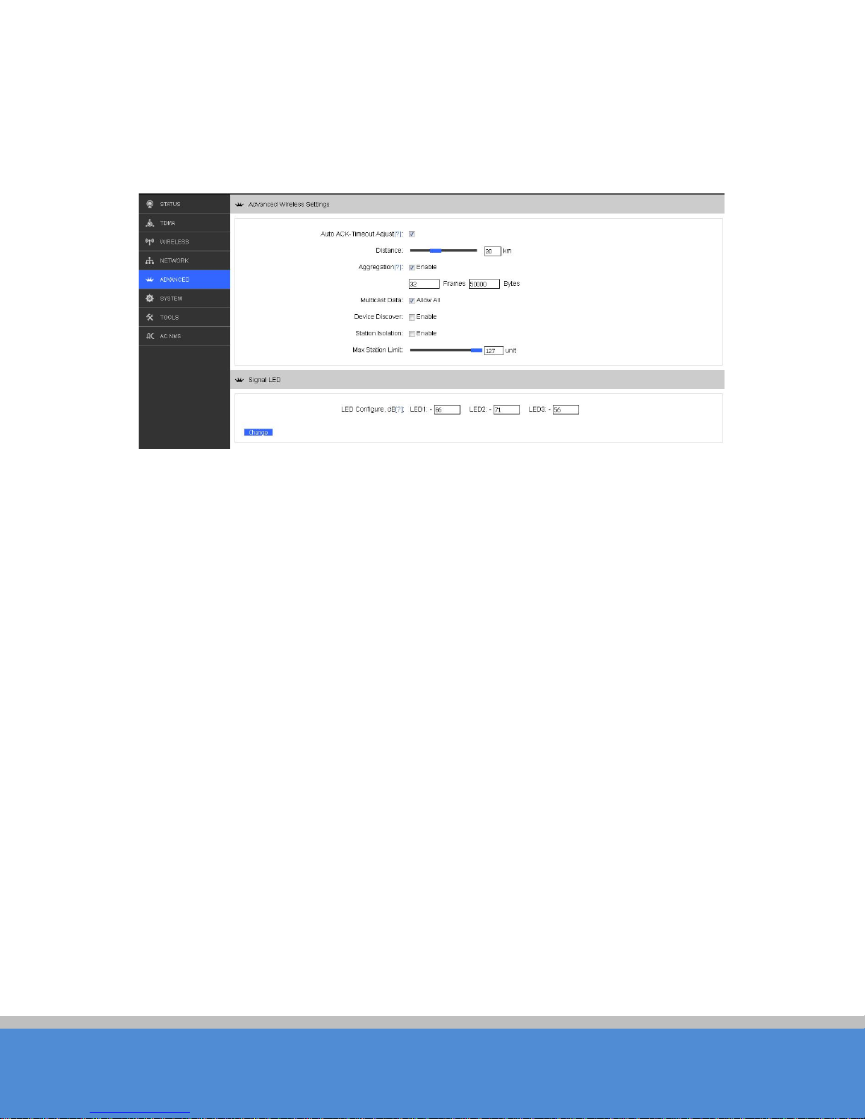
The Advanced page is shown in Figure 28.
USER MANUAL TB5F
Fig ure 28 Advanced
Auto ACK-Timeout Adjust: It is s uggested to enab le this func tion, so that the d istance
between 2 TB5F devices can be detected and all the related parameters can be
o p tim ize d to ac hie v e th e b e st link q u a lity.
D istanc e : The distance can be set manually if the Auto AC K-Timeout Adjust is disabled,
otherwise, the distance parameter is not allowed to be set. It is suggested the distance is
set a uto m atic a lly b y e na b lin g A uto A C K-Timeout Adjust parameter.
Aggregation: It enables several data frames of 802.11 to be aggregated and transmitted
out, thus improve the throughput. In d efault, it’s enab led.
Multicast Data: W hen it’s enabled, TB5F devices a llo w mu ltic as t fu n c tio n .
D e v ic e D isc o ve r: This feature should be used with the CreatC omm tool. The tool window
will display the MAC address of the device, IP address, and product name and so on.
Note: when the equipment is found by wireless way, please keep multicast sup p ort
enabled.
S tatio n Is o latio n : Enable this feature can make connection with an access point, the W DS
access points, W DS repeater equipment cannot communicate with each other, even
though the client IP duplicate nor of communication have any impact.
M ax S tatio n Lim it: B y s e tting it to lim it the num b e r o f c lie nts an d W DS clie nts th at are
connected to an access point, a WDS access point, a WDS repeater.
LED configure: This is to configure the signal strength value needed to light on. There are
3 LEDs on TB5F devices (LED3 value > LED2 value > LED1 value). The default values are
Page 30
Page 30
C O PYR IG H T ©2016 C reatC omm Technology
USER MANUAL TB5F
-86dBm, -71dBm and -56dBm. When LED1 value < signal strength < LED2 value, LED1
is lig hte d o n; When LED2 value < signal strength < LED3 value, both the LED1 and LED2
are lig h te d o n ; W he n s ig n a l s tre n gth > L E D 3 va lu e , all thre e L E D s are lig h te d o n.
9 S ystem
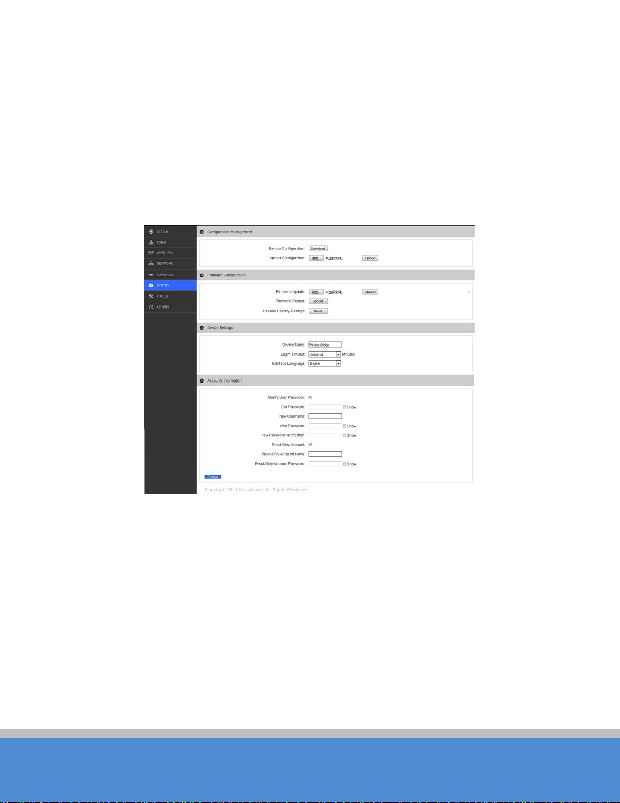
S ys te m p ag e is s h o w n in F ig ure 2 9 an d it is d ivid e d in to th e fo llo win g 4 p a rts :
C on figu ra tio n Management, Firmware, Device Setting, Accounts.
Fig ure 29 S ystem
Backup configuration: When clicking Download button, the current configuration can be
backed up to a file.
Upload configuration: W hen clicking browse, user can choose the backup configuration
file a nd th en c lic k up lo a d , so th at the c o n figu ratio n s to re d in th e b a c kup file c a n b e a p p lie d .
Firmware up d ate : C lick browse button and choose the file, and then click update button,
th e firmware can be updated to the latest version.
Firmware re b o o t: C lick the R eboo t b utton to reboot the device.
Reset to Defaults: C lick the R eset button to resto re to the facto ry d efault se tting s .
For default, all the factory settings are shown in the fo llo w in g tab le .
Page 31

Page 31
C O PYR IG H T ©2016 C reatC omm Technology
Ite ms
Default S e ttings
IP address
192.168.1.36
U s e r name
ad m in
Password
ad m in
W irele s s m o d e
S tation
SSID
W irele s s B ridg e
O utput power
H ig h
E nc ryp tio n
WPA->W P A 2 ->CCMP->Password:1234567890abc
N etw o rk m od e
B rid g e M o d e
Tab le 6 Main parameters at the factory s e ttings
Device name: It can be set to any name needed.
Login Timeout: Login Timeout setting.
Interface Language: Language setting.
USER MANUAL TB5F
Accounts: The user can modify the user name and password here.
10 Tools
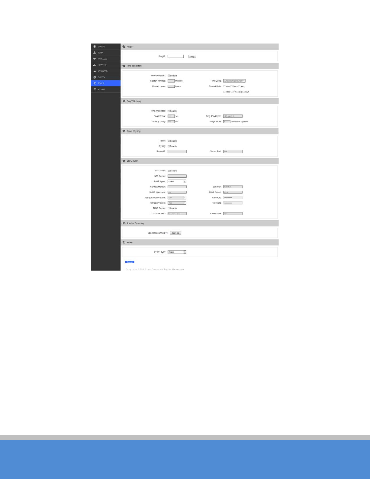
The To o ls p ag e is sh o w n in F ig u re 3 0 . T h is p ag e is d iv id e d into s ix p arts: P in g IP , T im e to
Restart, Ping W atchdog, Telnet/Syslog, NTP/SNMP,
Spectral Scanning and IP E R F.
Page 32
Page 32
C O PYR IG H T ©2016 C reatC omm Technology
USER MANUAL TB5F
Fig ure 3 0 To o ls
Ping IP: User can input the destination IP address of another device, and click Ping button.
If that destination device is successfully connected to the TB5F device, the result shows
A liv e , o th erw ise sh o w s N o t A live .
Ping Watchdog: The ping watchdog sets the TB5F Device to continuously ping a user-
defined IP address (for example, it can be the IP address of the AP the Client is
connecting to). If it is unable to ping under the user defined constraints, the TB5F device
will au to m a tic a lly re b o o t. It is h igh ly rec o mm ended that users enable this feature at the
side of “Wireless Station” and disable this feature at the side of “Access Point”.
Ping IP Address: S pecify an IP address of the target which will be monitored by Ping
Watchdog. If this feature is enabled at the sid e o f “W ire le s s S tatio n ”, P in g IP A d d re s s
should be the IP address of the AP the Client is connecting to.
Page 33

Page 33
C O PYR IG H T ©2016 C reatC omm Technology
USER MANUAL TB5F
P ing In te rva l: Specify time interval (in seconds) between the ping requests are sent by the
P ing W atc hd o g
S tartu p D e la y : s p ec ify in itial time d e la y (in se c o n d s ) u ntil firs t p ing req ue st is s e n t b y th e
P ing W atc hd o g
P ing F a ilu re: Specify the number of ping replies. If the specified number of ping replies is
not received continuously, the Ping Watchdog will reset the WIFI only.
Telnet:When telnet is enabled, the user can input command “Telnet 192.168.1.36” in the
DO S window of Windows XP or Windows 7 PC , and then telnet to the TB5F and
ma n ip u late the T B 5 F d e vic e. W he n teln e t is d is a b le d , th is o p era tio n is d is a b le d .
S ys lo g : W hen it’s enabled, and the System Log server’s IP is also set here, the log
info rm atio n w ill b e o utp u t to the S yste m Lo g s e rv e r a u to m atic a lly .
NTP Server: If this NTP server is set, and the TB5F device can access to this NTP server.
TB 5 F d e v ic e auto m atic a lly c a lib ra te th e time and d ate information with the NTP server and
sho w the time information in the S tatus p age.
S N M P G roup : W hen this function is enabled, use can check the working condition and
information of the TB5F device.
Spectral S canning: The function can view around the 20MHz bandwidth frequency of the
use situation; this can help you configure the device to avoid busy frequency. When the
spectral scanning is ru nnin g , u s ers cannot do any configuration operations on the device
page.
IP E R F: It is used to test network throughput. User can configure it to server or client.
S e rve r: whe n it is a s e rv e r, it waits c lie n t to c o n n e c t.
C lient: w h e n it is a c lie nt, it s e n d s c o n n e c t re q u e s t to s erv e r.
IP E R F d u a l: c lie nt se n d s a n d rec e iv e s ig na l a t s a me tim e.
IP E R F S e rver: IP a d d ress of server.
IPERF Thread: the number of iperf thread. If using more thread, the throughput is high.
IPERF Time: how long the iperf run.
IPER F Inte rval: the time b e tween two results show.
N o te:
If users want to modify the parameters of Ping Watchdog, please disable it first and
then apply. When the web page shows that Ping Watchdog is really disabled, users can
now re -e n a b le it w ith m o d ifie d p a ra m e te rs.
Page 34
Page 34
C O PYR IG H T ©2016 C reatC omm Technology
USER MANUAL TB5F
11 AC NMS
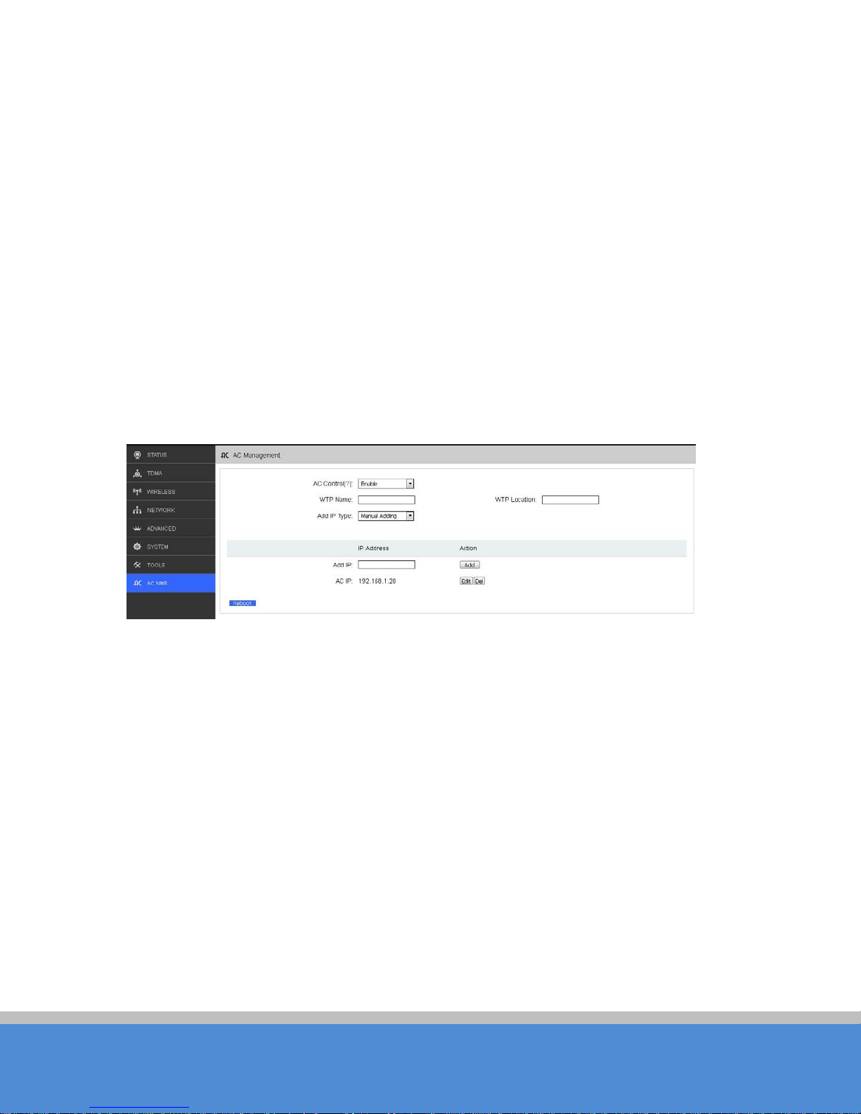
The AC NMS page is shown in Figure 31.If you want the device to join the AC
management you need AC management at first and then go to the A C NMS page to
enable the AC control.
WTP name: indicates the name of the device to show on the AC management.
W TP lo c atio n : indicates the location information of the device to show on the AC
management.
Add IP Type
A C IP : AC IP is the IP address of the AC management witch this device should be joining
in. It can be added up to eight.
When the AC control is enabled and the IP address is matched, the device can be
on-line in A C man a g e m e n t, a c lie nt d e vic e m us t b e a s s o c ia ted to an access point device
whic h is o n-line on the AC , and then it can be on-line on the AC management.
When AC control is enabled, users can not configure the device through the device
pages except the AC NMS.
:Users can choose Manual Adding or Automatic G et.
Fig ure 30 AC NMS
12 Logout
C lic k th e lo g o u t b u tto n , it will lo g o ut th e d e v ic e and re tu rn to the lo g in p ag e .
13 N etw o rk C o n fig ura tio n E xa mp le s
13.1 A P and S tation N etwork
In the point-to-point working scenario, user can configure one TB5F device to AP, and
another to station mode, shown in Figure 32.
Page 35
Page 35
C O PYR IG H T ©2016 C reatC omm Technology
USER MANUAL TB5F
Fig ure 31 AP and S tation netwo rk
To make the above network working, user need to configure the two devices to be
as s o c ia te d . The d e tail c o n figu ratio n s are d es c rib e d in th e follo win g :
1. C onfig ure the two d e vice s to b rid g e m o d e , d is a b le th e firew a ll, a nd s e t d iffere nt LA N IP
for the two devices, the LAN IP should be on the same segment.
2. In wireless menu, configure one device to AP mode and the other one to station mode,
set the same SSID, the same channel bandwidth (20MH z fo r d e fault), and set the
same encryption and password for both of the devices.
3. After the above setting is done, wait for a while. Using one computer to ping the other
one. If the devices are configured correct, they will be associated and the ping will ge t
th e re p ly.
13.2 W DS AP, WDS Station, WDS Repeater Network
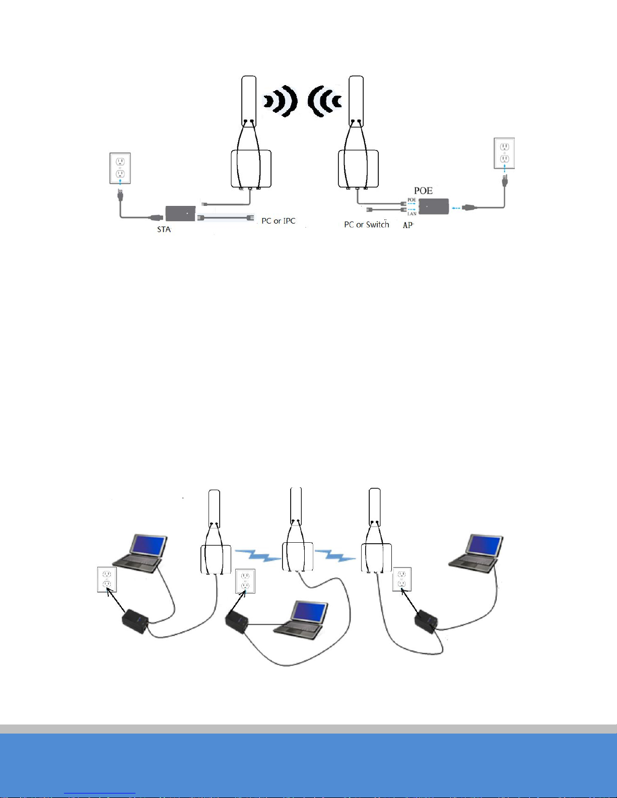
Fig ure 32 W D S N e two rk
Page 36
Page 36
C O PYR IG H T ©2016 C reatC omm Technology
USER MANUAL TB5F
If there is a block, such as a building is in between the point-to-point connection, one
TB5F device can be put between the PTP connection as a relay, w h ic h is “W D S A P , W D S
Station, WDS Repeater” network, shown in the above Figure33.
Three TB5F devices need to be configured as shown in Figure 33:
1. Configure the 3 devices to be bridge mode.
2 . In the wire les s m e n u , ma ke th e fo llo win g c o n fig u ra tio n s :
Configure the 3 devices to WDS AP/WDS Repeater/WDS Station separately
C onfigure the 3 devices’ SSID to be the same
C onfigure W DS AP and WDS Repeater frequency to be the same, for example:
5825MHz
C onfigure the encryption method and password to be the same.
3. To verify if the network is correctly setup, please use the computer connected to one of
the three devices to ping the IP of any of the other two devices. If the ping is successfully,
the ne twork co n n e c tion works co rrec tly.
13.3 Router Mode
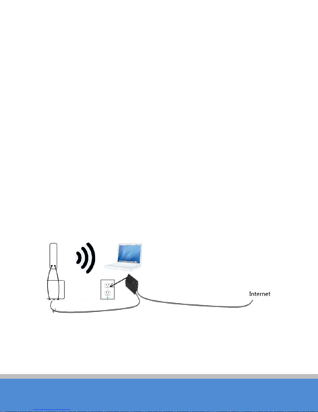
In the Router mode, the TB5F works as a router and the network connection is shown in
Figure 32. The PoE port of the PoE adaptor is connected to the TB5F device’s PoE port,
and the LAN port of the PoE adaptor is connected to the internet. Meanwhile, the LAN
port of TB5F device is connected to one computer, and then user can configure the
device.
Fig ure 33 Route mode
After the above connection is done, configure the TB5F device using the web based
configuration menu.
Page 37

Page 37
C O PYR IG H T ©2016 C reatC omm Technology
USER MANUAL TB5F
1. In wireless page, set the device to ro ute m o d e , d is ab le the fire wall. If the in te rn e t
provided by the ISP (TB5F connected to) has a DHC P server, user can set TB5F’s
WAN mode to DH C P (Dynamic IP) so that it can obtain the IP address automatically.
If the internet provided by the ISP(TB5F connected to) doesn’t have a DHC P server,
user need to manually configure all the parameters given by the ISP, such as the WAN
IP, WAN Netmask, LAN IP, LAN Netmask, Default gateway, Primary DNS, Secondary
DNS.
N o te : LAN IP address and WAN IP address cannot be in the same IP segment. For
example, if LAN IP is 192.168.1.*, then WAN IP must be set to 192.168.2.* or
192.168.3.*.
2. In wireless page, set wireless mode to Access Point, set SSID to a random name, and
set output power to a value needed(Max output power is recommended in the outdoor
long distance environment). Then the user needs to choose a wireless channel and an
encryption method.
3. Enable DHC PD at the Tools page. Please refer to chapter 10 for DHC PD setting.
4. W hen the above settings are done, use a computer to connect to TB5F device, and
then check whether the connection is successfully.
N o te : U sers can check whether the connection is successfully by ping TB5F device’s
WAN IP address. If the ping is successfully, this connection is successfully.
FAQ
1. The device cannot be started after power on.
1. The Ethernet cable between the TB5F device and the PoE adaptor is more than 40
meters long.
2. The Ethernet cable quality is not good enough, and it should be Cat 5e or even Cat 6
c a b le.
3. The RJ-45 plugs are not well c o nn e c te d .
2. Cannot be restored to the factory se tting
Please manually push the Reset button for 5S~10S, then the user can log in the device by
typing the default IP address 192.168.1.35.
3. My computer cannot be connected to the TB5F Access Point.
Please try the following method to solve the problem:
Page 38

Page 38
C O PYR IG H T ©2016 C reatC omm Technology
1. Adjust the direction of the TB5F device.
Please rotate the TB5F device since the antenna inside the device is directional.
2. Switch to other wireless channel
Switc h to o the r wire le s s c ha n ne l cause there are much interferences in this channel.
3. Turn off the other interference sources
Maybe there are other W IFI devices nearby and cause interferences. Try to turn off
other W IFI devices nearby, or move TB5F to another clean environment.
USER MANUAL TB5F
4. The signal strength between 2 TB5F devices is too weak, and
throughput is low.
1. The TB5F AP and Station devices are not Line-of-S ight, o r the re are b lo c ks like a
building in between the AP and Station devices.
2. T h e S tatio n d e vic e a n d A P d e vic e is no t a lig n e d very w e ll, in c lu d in g b o th h o rizon tally
and ve rtic ally, s in c e the a n te nn a o f the TB 5 F is d irec tio n a l.
3. T h e S tatio n d e vic e is ins talle d in th e win d o w s , and th e w in d o w s g la ss sh ie ld s the
wire le s s s ig n a l.
4. The distance between the AP and Station devices is too far.
5. T he s ig nal strength is high, but the throughput is low
1. There are two much interferences, or multi-path interferences. For example, there are
two much 2.4G Hz or 5.8GHz WIFI device working nearby.
2. The RJ45 ports of the TB5F device don’t work well.
6. During the point-to-p o in t o r p o int-to-m u lti-point connection, when ping
from one device to another, the latency is too long or the packet is lost.
1. Isolate the several APs if they are connected to one PoE switch.
2. The RJ45 ports are not connected very well.
7. The internet access is lost and the interne t sp eed is low.
1. There are too much stations connected to one AP.
2. A P s ig n a l is to o w e e k.
Page 39

C o p yright © 2 0 16 CreatC omm Technology. A ll rights re s e rve d . CreatComm, the CreatComm logo, are trademarks of C rea tC omm. A ll o the r
doc u me n t may b e sub jec t to c han ge w itho ut n o tice . To lea rn m o re a b out CreatComm products, visit www.creatcomm.com .
TB5F
Page 39
USER MANUAL
3. There are interference source nearby.
4. C heck the number of users and the max internet speed provided by the ISP.
8. The signal strength is high, but the throughput is low
1. There are two much interferences, or multi-path interferences. For example, there are
two much 2.4G Hz or 5.8GHz WIFI device working nearby.
2. The RJ45 ports of the TB5F device don’t work well.
9. During the point-to-p o in t o r p o int-to-m u lti-point connection, when ping
from one device to another, the latency is too long or the packet is lost.
1. Isolate the several APs if they are connected to one PoE switch.
2. The RJ45 ports are not connected very well.
10. The internet access is lost and the internet speed is low.
1. There are too much stations connected to one AP.
2. A P s ig n a l is to o w e e k.
3. There are interference source nearby.
4. C heck the number of users and the max internet speed provided by the ISP.
O rd ering Info rmatio n
Creatcomm Technologies Co., Ltd.
Suite619, Build A, Modern Plaza, No.18 W eiye Ro ad K un shan Development Zone,
Jian gs u, China. 215300
Tel: +86-512-86186383
Email: [email protected]
Website: www.creatcomm.com
company and product names may be trademarks of their respective companies. While every effort is made to ensure the informatio n given
is accurate, C reatC omm d o e s n o t a c ce p t liab ility fo r an y e rro rs o r m is tak e s w hic h may a ris e . S pe c ificatio ns and other info rm a tion in this
Page 40

Page 40
C O PYR IG H T ©2016 C reatC omm Technology
USER MANUAL TB5F
 Loading...