

Page 1
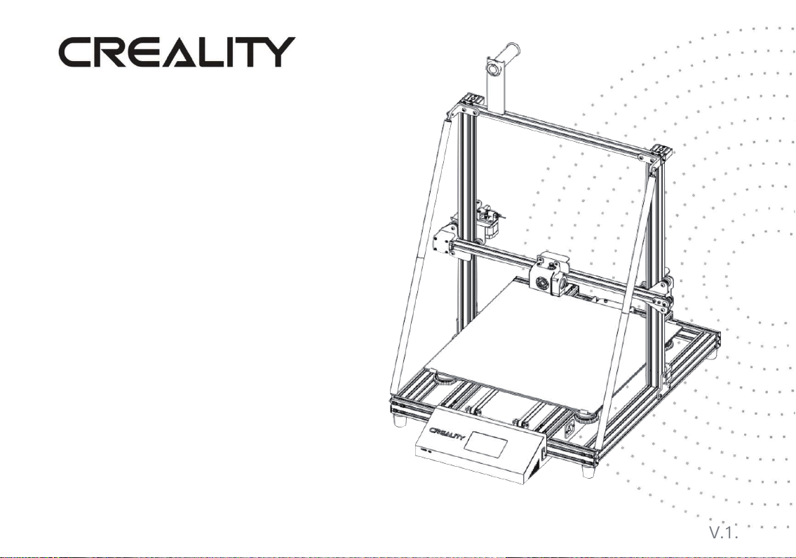
CR-10 Max 3D Printer User Manual
This User Manual is prepared for standard CR-10 Max.
Please plug the power cord into a three-hole power jack.
Detailed instructions for use are available in the TF card.
V.1.0
Page 2

CONTENTS
Dear Consumers,
Thank you for choosing our products. For the best experience, please read the instructions before
operating the Printer. Our teams will always be ready to render you the best services. Please contact
us via the phone number or e-mail address provided at the end when you encounter any problem
with the Printer.
For a better experience in using our product, you can also learn how to us
following ways:
View the accompanied instructions and videos in the TF card.
Visit our official website www.cxsw3d.com to find relevant software/hardware information, contact
details and operation and maintenance instructions.
e the Printer in the
Notes
1. Do not use the printer in any way other than described herein in order to avoid personal injury or property damage.
2. Do not place th e printer near any he at sour ce or f lammabl e or ex plosi ve ob ject. We sugge st p lacin g it in a well -
ventilated, shady and low-
3. Do not expose the printer to a vibrant or any unstable environment, as this may cause poor print quality.
4. We sugg est usi ng fila ments r ecommend ed by m anufact urer to avoid the bl ockin g of extrusion structur e and the
damage of machine.
5. Do not use any other power cord except the one supplied. Always use a grounded three-prong power outlet.
6. Do not touch the nozzle or hotbed duri
7. Do not wear glo ves or loose c lothing when o peratin g the p rinter. Such c loths m ay beco me tang led in the prin ters
moving parts to lead to burns, possible bodily injury or printer damage.
8. When cleaning debris from the printer hotbed, always use the provided tools. Do not touch the nozzle directly when
heated. This can cause personal injury.
9. Clean the
10. Children under 10 years of age should not use the printer without supervision.
11. This machine is equipped with a security protection mechanism. Do not manually move the nozzle and printing platform
mechanism manually while booting up, otherwise the device will automatically power off for safety!
printer frequently. Always tu rn the power off w hen clea ning, a nd wipe with a dry c loth to remove dust,
adhered printing plastics or an y other material off the frame, guide rails, or wheels. Use gl ass cle aner or isopropyl
alcohol to clean the print surface before every print for consistent results.
dust environment.
ng printing to avoid burns or personal injury.
Introduction..................1
General List..................2
Device Installation........3
Cable Connection.........4
Screen Information.......5
Loading Fil
ament..........6
Bed Leveling.................7
Software Installation….9
First Printing.................10
Circuit Wiring...............11
Page 3
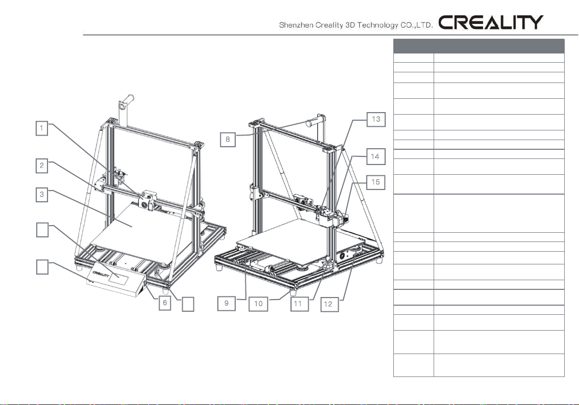
1. Introduction
1
8
2
3
4
5
1. Nozzle kit & auto leveling
2. X-axis limit switch
3. Printing platform
4. Touch screen
5. TF card slot & USB port
6
7
6. Power switch
7. Power socket
8. Filament holder
9. Y-axis limit switch
10. Z-axis motor
9
10
11
12
11. Coupling
12. XL bed-leveling nut
13. Extruder (E) motor
14. Filament detector
15. X-axis motor
13
14
15
Parameters
Model
Molding Size
Molding Tech.
Nozzle Number
Slice Thickness
Nozzle
Diameter
Precision
Fliament
File Format
Working Mode
Slice Software
Power Supply
Spec.
Hotbed 750W, 24V, input: 100-240V AC, o
Machine Power
Hotbed Power
Hotbed Temp.
Nozzle Temp.
Resume Print
Filament
Detector
Dual Z-Axis
Auto Leveing
Language
Selection
Operating
System
CR-10 Max
450 x 450 x 470mm
FDM
1
0.1mm-0.4mm
0.4mm 0.8mm
±0.1mm
φ1.75mm PLA
STL/OBJ/AMF
Online or TF card offline
Creality Slicer/Cura/
Repetier-Host/Simplify3D
Motherboard 75W, 24V, input: 100-240V AC,
Windows XP/Vista//7/8/10 MAC/Linux
output: 24V;
24V
750W
700W
≤100℃
≤
25 0℃
Yes
Yes
Yes
Yes
EN/CN
utput :
1
Page 4
M
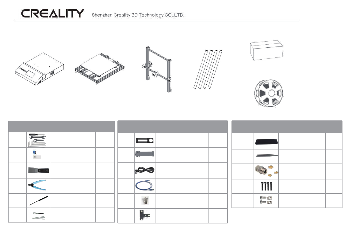
2. General List
Tool Box
Tool List
No. Image Name Qty
1 Wrench & Screw Driver 1 Set
2 TF Card & Reader 1 Set
3 Spatula 1
4 Pliers 1
5 Nozzle Cleaner 1
6 Cable Ties 2
2
Printing Platform Support Rod
Gantry FrameBase Frame
No. Image Name Qty
7 Filament Holder 1
8
9 Power Cord 1
10 USB Cable 1
11
12
Filament Holder Tube with
Nuts
4X20 Hexagon Socket Head
Cap Screws
T-type Fixed block
10
1
2
Filament (1kg)
No. Image Name Qty
13 Spacer 1
14 Feeler Gauge 1
15 Spare Parts 1 Set
16 M5x45 Sems Screw 4 Sets
17
M4X8 Head Cap Screw
and M4 T-Nut
2 Sets
Page 5
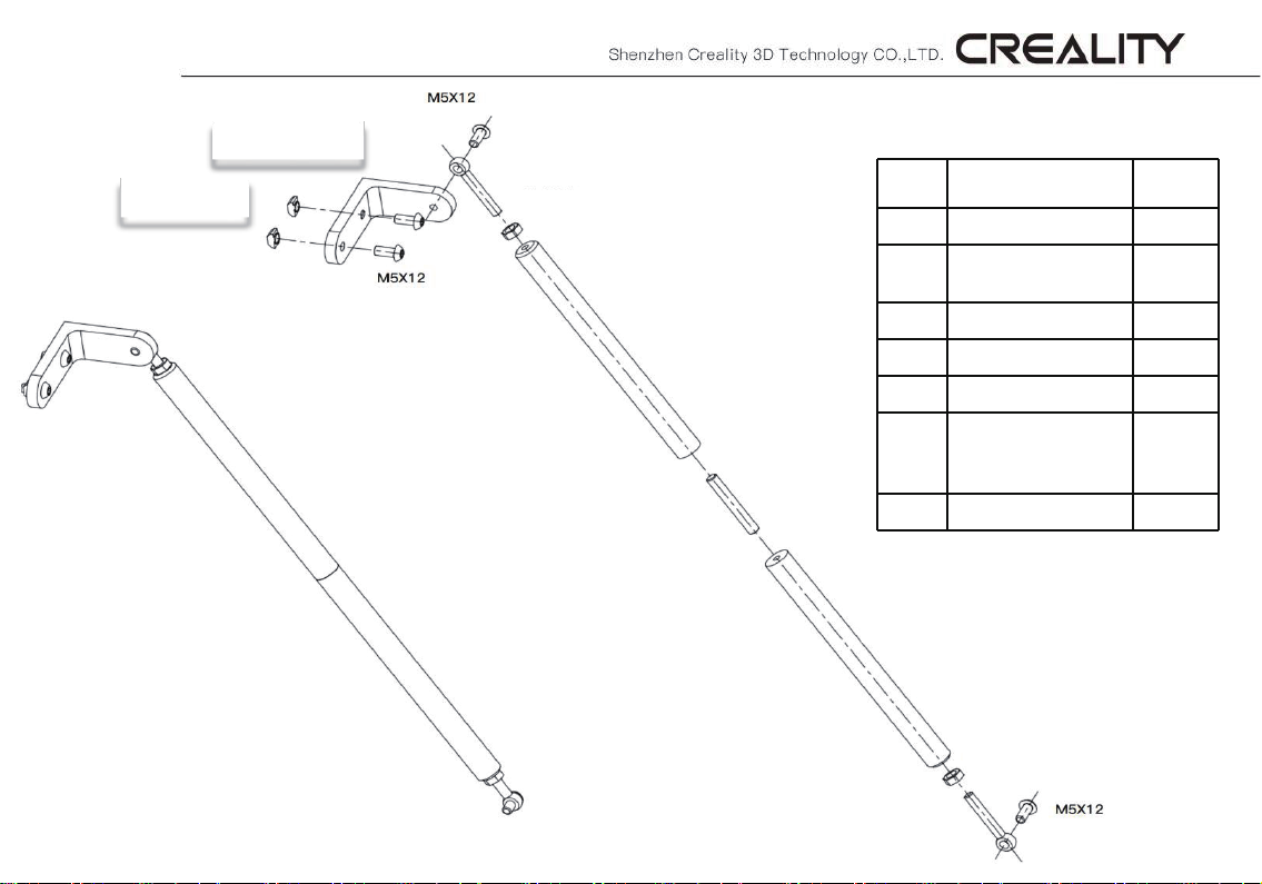
M5 T-nut
Pull rod joint
Eye bolt M6 x 35
M6 Nut
Pull rod
Pull rod details
No. Name Qty
1 Pull rod 4pcs
2
3 Eye bolt M6 x 35 4pcs
4 M6 nut 4pcs
5 Set screw M6 x 40 2pcs
L-type pull rod
connecting fittings
2pcs
M6X40
Screw rod
Pull rod
Eye bolt M6 x 35
M5 x 12 Hexagon socket
6
7 M5 T-nut 4pcs
button head screw
M6 Nut
8pcs
3
Page 6
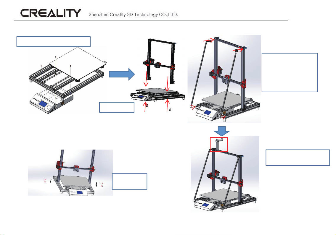
3. Device installation
M4X20 Head Cap Screw 4pcs
1. Printing Platform Installation
3. Gantry Frame Fixation
M5X45 4pcs
2. Gantry Frame Installation
M4 x 20 6pcs
T block 2pcs
Support Rod 4pcs
M6 x 40 Screw rod 2pcs
Eye Bolt M6 x 26 2pcs
M6 Nut 4pcs
M5 x 12 Screw 8pcs
M5 T-Nut 4pcs
4. Support Rod
Installation
M4 x 8 Head cap screw 4pcs
M4 T-Nut 2pcs
5. Filament Holder Installation
4
Page 7
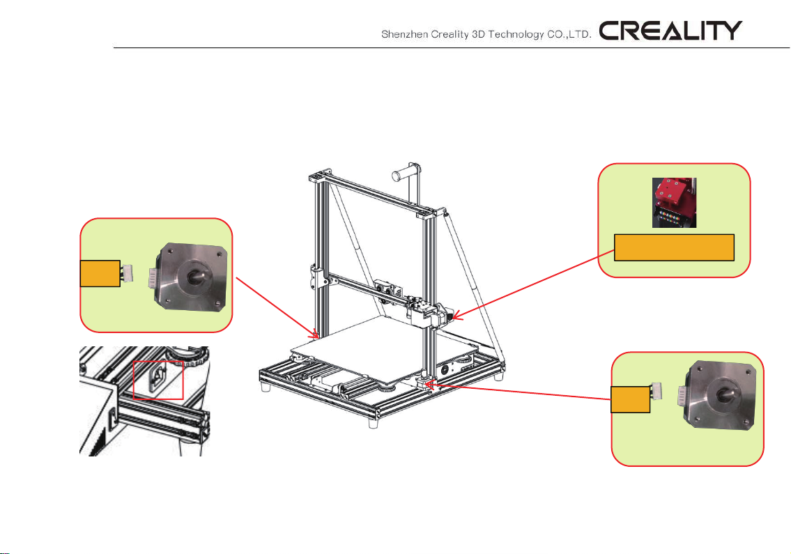
4. Cable Connection
Z2
*Plug the power cord into a three-
hole power jack.
Ribbon Cable
Z1
5
Page 8
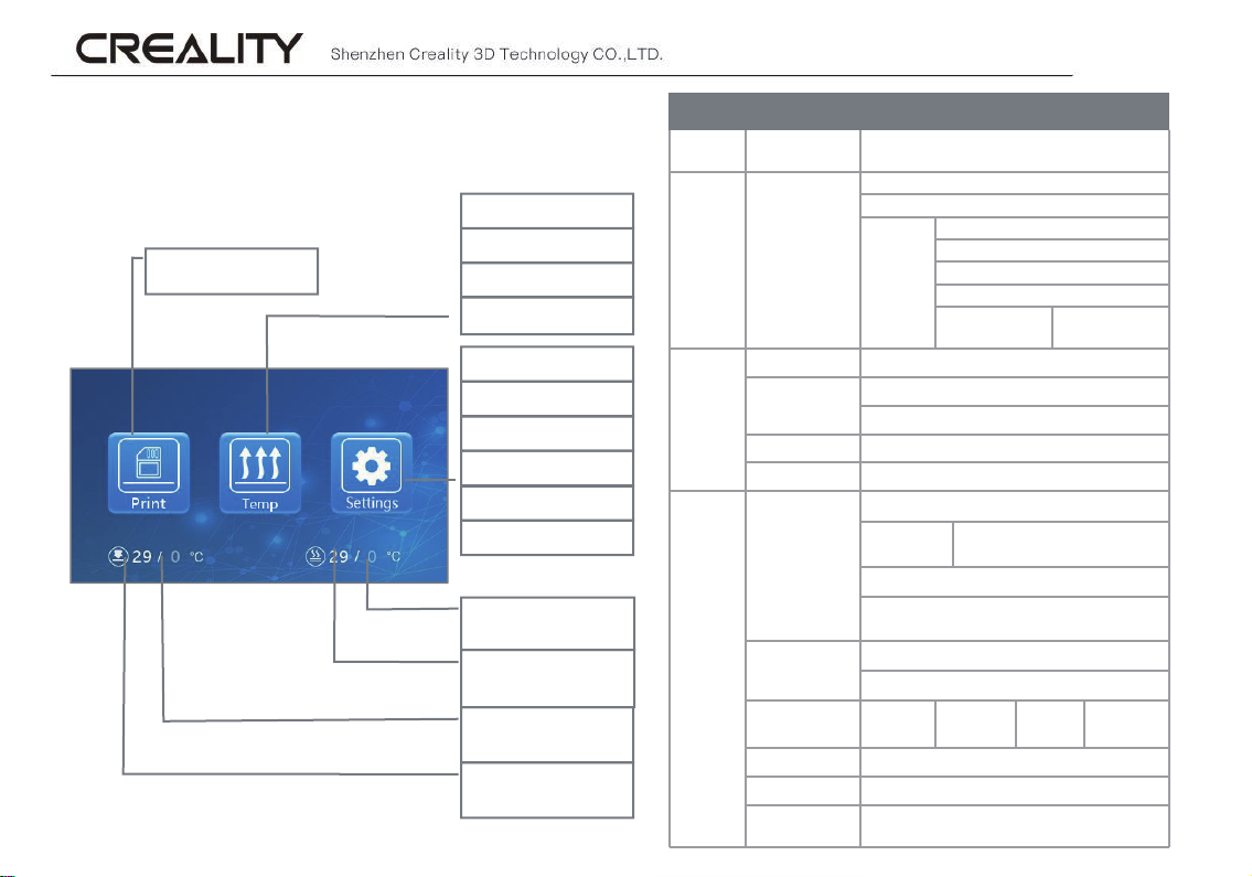
5. Screen Information
Select “Print”
6
Automatic
Manual
Cooling
Fan
Leveling
Refuel
Moving
Motor
Print info
Language
Set temperature
of hotbed
Current
temperature of
hotbed
Set temperature
of nozzle
Current
temperature of
nozzle
Main
Menu
Print TF card
Temp
Setting
Sub Menu Explanation
Automatic
Manual
Cooling Yes\No
Fan On\Off
Leveling
Refuel
Moving
Motor off Yes \No
Language English\Chinese
Printer info
Screen Information
Stop
Pause/Continue
Print speed
Nozzle temp.
Adjust
Z-axis: Z home, +0.1mm, -0.1mm
AUX
leveling
Platform measurement (measu
X-axis
Device model, firmware version, printing size,
Hot-bed temp.
Fan
Temperature
up/Stop
PLA \ABS(195°\240°)
Nozzle preheat
Hot-bed preheat
Please click numbers (①~⑤) to
AUTO leveling (switch)
Withdraw
Feed
Y-axis Z-axis
official website
Continue/Stop
assisted leveling......
rement parameters)
Z home
Page 9
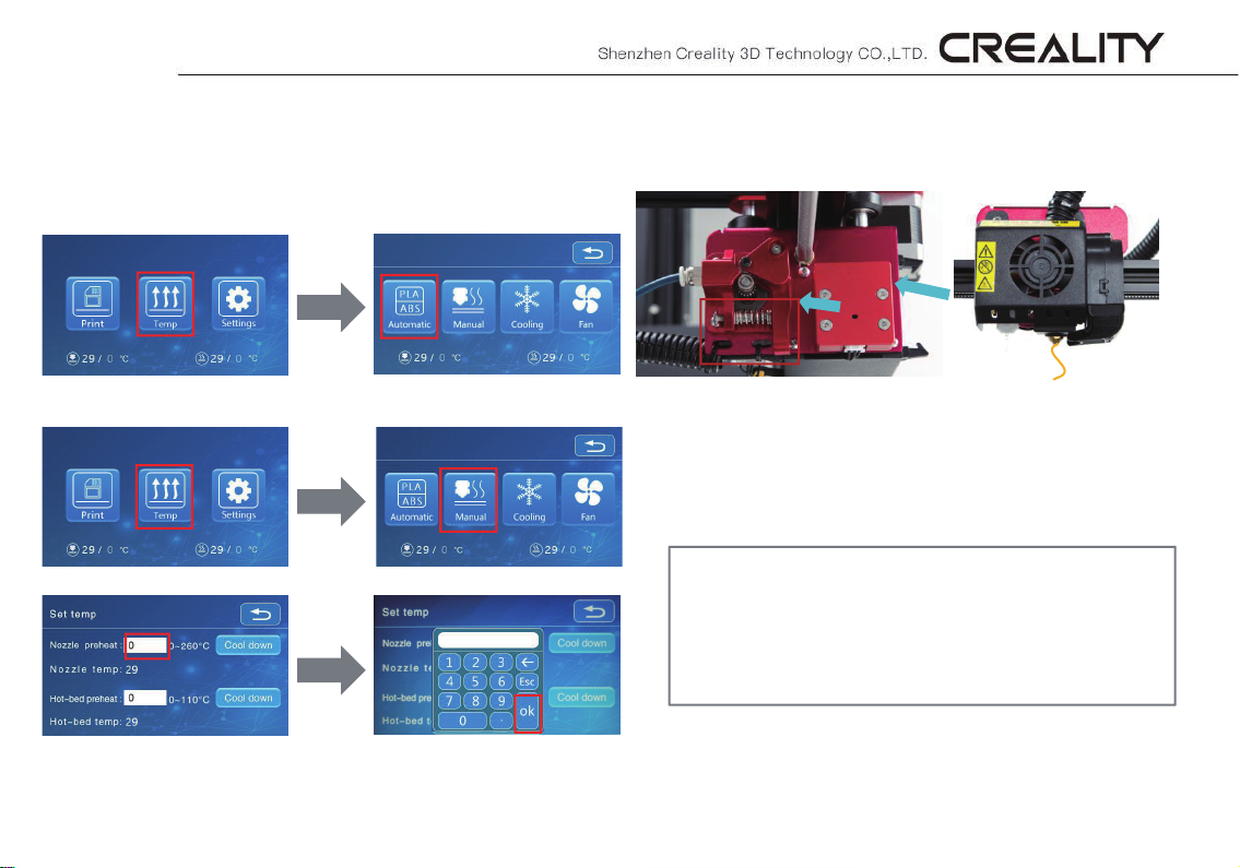
6. Loading Filament
Preheat
Method 1.
Method 2.
Feeding
Go through the filament detector to press and hold the extruder
spring. Insert the filament to the position of nozzle through the hole on the
extruder. Continue feeding until you see filament extrude from the nozzle.
1. Cut the filament near the extruder and feed new filament slowly until new
filament is fed into the feeding pipe.
200
(Or)
2. Preheat the nozzle and replace the used filament with new filament.
7
Replacing Filament During Printing:
Page 10
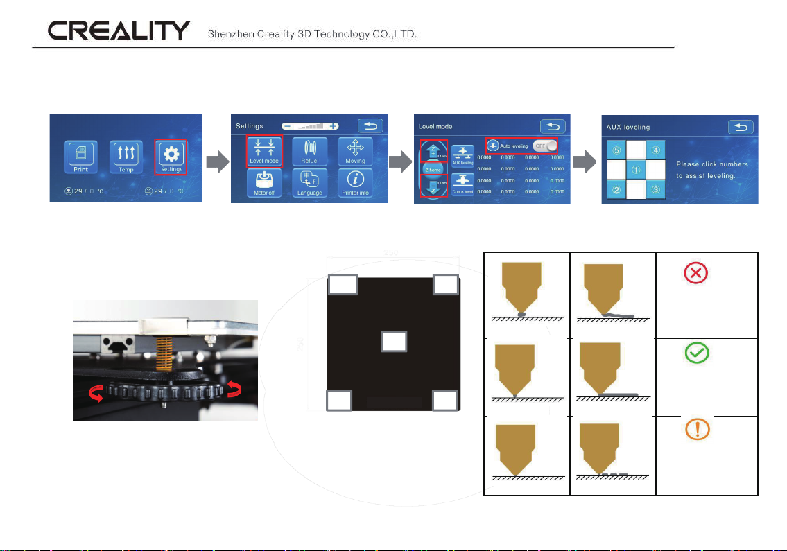
7. Bed Leveling
1. Tighten four leveling nuts at the bottom of the platform before
initial leveling.
2. Select “Settings” → “Leveling Mode” → “Assisted Leveling”,
click number ②.
5
1
2
3. Adjust the platform height by turning the knob underneath. Adjust the printing platform and
nozzle to enable the two to just fit each other perfectly with a gap of 0.05mm. Use a piece of A4
paper to assist with the leveling to make sure that the nozzle just scratches on this A4 paper.
4. Adjust all leveling nuts with four corners.
5. Click number ① to test if the platform gap is proper.
6. Repeat abov
e steps once or twice if necessary.
4
3
The nozzle is too far
away from the platform,
so the filament fails to
adhere to the platform.
Filament is extruded
evenly to adhere to
the platform.
The nozzle is too close to
the platform, and the
filament is not extruded
insufficiently, and even
the platform is scratched.
8
Page 11
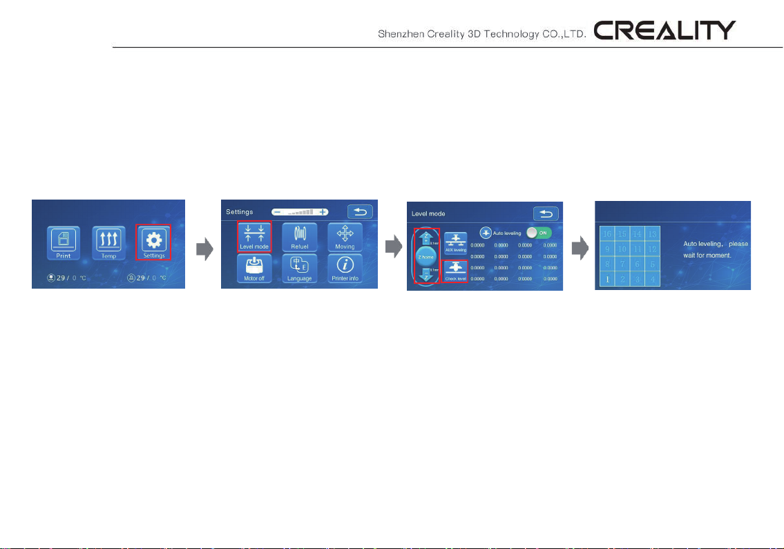
Automatic leveling
If you need to do automatic leveling , you can change to it in the following interface:
Detailed instructions for use are available in the TF card!
9
Page 12
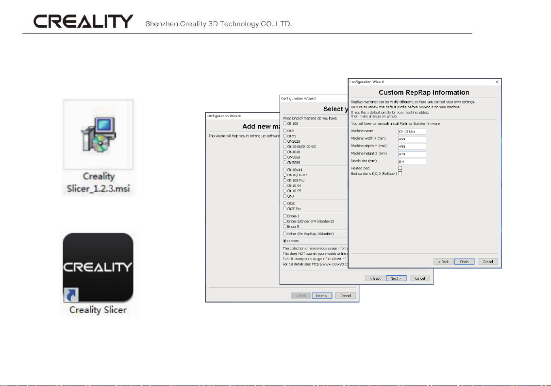
8. Software Installation
1. Double click to
install the software
2. Double click to
open the software
Select language → Next → Select your machine → Next → Finish
3.
10
Please refer to the Slice Software User Manual in the TF card for details of software use!
Page 13
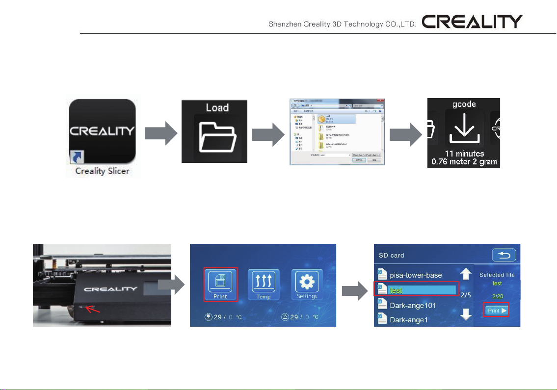
9. First Printing
1. Slicing
Open the software → Load → Select the file → Wait for slicing to finish ,and save the gcode file to TF card.
* File name must be English or number. Don’t use Chinese or special symbols
2. Printing
Insert the TF card → Print → Select Model → Print
11
Page 14

Tips
1. Terms about after-sales service are available in the after-sales service card.
2. Slight scratch of profile and slight tilt of platform is normal if printing can
still be done smoothly.
3. Users must abide by laws and regulations in the location of machine and
corresponding countries/regions and adhere to work ethics and are strictly prohibited
from using our 3D printers to print any product
regulations in the location of machine and corresponding countries /regions to make
the most of 3D printers, promote the harmonious growth of market economy,
consciously enhance industry self-discipline, establish a positive image of 3D printers,
ensure well-organized, legitimate and healthy activities about product certification and
quality management system certi
printers and avoid related responsibilities.
fication, highly mitigate risks from the use of 3D
or object that violate laws and
Page 15

Page 16

The revision date: July 1 ,200 19
SHENZHEN CREALITY 3D TECHNOLOGY CO.,LTD.
11F&Room1201,Block3,JinChengYuan,TongshengCommunity,Dal
ang,LonghuaDistrict,Shenzhen,China,518109
Official Website: www.creality3d.cn
Tel: +86 0755-85234565
E-mail: [email protected] [email protected]
 Loading...