

Page 1

Page 2

Sewing Machines and
Processes
Sewing Machines and Processes presents modern engineering fundamentals of sewing processes and machines for the complete spectrum of sewing stitches. The book
covers the construction, working principles, and the mechanics of single systems,
such as needle motion, thread tension and compensation devices, material transportation, and grippers and knives.
Describing elements for chain stitch, overlock, covering stitches with multiple
needles, the book also discusses their kinematic analysis using modern numerical
methods and software. Additional focus is given to the thread motion, dynamics,
tension measurement, and quality assurance. Readers will learn the main factors
for issues with sewing quality and be able to use and adjust modern industrial and
household machines for textiles and composites.
The book will interest researchers studying and working in the apparel industry
and textile production/manufacturing. It will also benet graduate students taking
courses in Apparel Technology, Sewing Technology, Sewing Processes, and Joining
Technology of Texti les.
Page 3

Page 4

Sewing Machines and
Processes
Edited by
Yordan Kyosev
Page 5

We acknowledge support for the Open Access publication by the Saxon State Digitization Program for Science
and Culture.
Designed cover image: Shutterstock and Yordan Kyosev
First edition published 2026
by CRC Press
2385 NW Executive Center Drive, Suite 320, Boca Raton FL 33431
and by CRC Press
4 Park Square, Milton Park, Abingdon, Oxon, OX14 4RN
CRC Press is an imprint of Taylor & Francis Group, LLC
© 2026 selection and editorial matter, Yordan Kyosev; individual chapters, the contributors
Reasonable effor ts have been made to publish reliable data and information, but the author and publisher cannot
assume responsibility for the validity of all materials or the consequences of their use. The authors and publishers have attempted to trace the copyright holders of all material reproduced in this publication and apologize to
copyright holders if permission to publish in this form has not been obtained. If any copyright material has not
been acknowledged please write and let us know so we may rectify in any future reprint.
The Open Access version of this book, available at www .taylorfrancis .com, has been made available under a
Creative Commons Attribution (CC BY) 4.0 International license.
Any third-party material in this book is not included in the OA Creative Commons license, unless indicated
otherwise in a credit line to the material. Please direct any permissions enquiries to the original rightsholder.
Trademark notice: Product or corporate names may be trademarks or registered trademarks and are used only
for identication and explanation without intent to infringe.
Library of Congress Cataloging‑in‑Publication Data
Names: Kyosev, Yordan editor
Title: Sewing machines and processes / edited by Yordan Kyosev.
Description: First edition. | Boca Raton, FL : CRC Press, 2026. |
Includes bibliographical references and index.
Identiers: LCCN 2025010856 (print) | LCCN 2025010857 (ebook) |
ISBN 9781032274966 hardback | ISBN 9781032274973 paperback |
ISBN 9781003293071 ebook
Subjects: LCSH: Sewing machines
Classication: LCC TJ1510 .S44 2026 (print) | LCC TJ1510 (ebook) |
DDC 646.2/044–dc23/eng/20250612
LC record available at https://lccn.loc.gov/2025010856
LC ebook record available at https://lccn.loc.gov/2025010857
ISBN: 978-1-032-27496-6 (hbk)
ISBN: 978 -1- 032-27497-3 (p bk)
ISBN: 978 -1- 003 -29307-1 (ebk)
DOI: 10.1201/9781003293071
Typeset in Times
by Deanta Global Publishing Services, Chennai, India
Page 6

Contents
Preface......................................................................................................................vii
Editor ........................................................................................................................ix
Contributors ............................................................................................................... x
Chapter 1 History of Sewing .................................................................................1
Hassan Saeed
Chapter 2 Sewing Stitch Types ........................................................................... 10
Yordan Kyosev and Hassan Saeed
Chapter 3 Stitch Formation Process ....................................................................26
Yordan Kyosev
Chapter 4 Needle Thread Motion ....................................................................... 57
Yordan Kyosev
Chapter 5 Sewing Needles .................................................................................. 69
Daniela Sofronova
Chapter 6 Sewing Needle: Mechanism and Forces ............................................92
Daniela Sofronova
Chapter 7 Sewing Threads ................................................................................ 111
Ruth Kneisel
Chapter 8 Thread Consumption for Different Stitch Types .............................. 162
Yordan Kyosev
Chapter 9 Material Transport ............................................................................ 174
Hassan Saeed
Chapter 10 Quality Control during the Sewing Process ..................................... 192
Denise Lenk and Johannes Taesler
v
Page 7

vi Contents
Chapter 11 The Evolution of Embroidery Machines .......................................... 205
Cindy Elschner and Judith Hahn
Chapter 12 Embroidery of Conductive Threads in Textiles ...............................228
Daniela Sofronova and Radostina A. Angelova
Chapter 13 Spacer Stitching ................................................................................260
Hassan Saeed
Chapter 14 Sewing Machines for Leather and Other Heavy Products ............... 275
Tatjana Spahiu, Liliia Chertenko and Ermira Shehi
Chapter 15 Automated Sewing Places ................................................................ 295
Sophie Herz, Karl Hesse and Laura Spindler
Index ...................................................................................................................... 313
Page 8

Preface
All people wear clothes, produced by connecting multiple pieces of fabrics by sewing. For more than 100 years, sewing machines have been available in most homes
and, for this reason, are often considered a simple device that grandmothers are able
to use. The simplicity of using sewing machines and the stability of their work are
a result of a large set of genius engineering inventions. Modern machines perform
more than 100 stitch building cycles in one second, operating with high accuracy
and reproducing highly exible sewing threads. The goal of this book is to explain
how this works.
This book is written to provide a background to understanding the sewing machine
and its processes in sufcient depth for the university students in my lectures at TU
Dresden and the lectures of all colleagues worldwide. It provides the fundamentals
for workers in production companies and machine developers. At the same time, the
authors have tried to keep their explanations as understandable as possible in order
to be useful to a broad audience of any interested person without an engineering
background.
My initial goal was to provide very detailed explanations of all related areas, principally all the knowledge that I have collected during more than 35 years of using
sewing machines in my education, consultancy and private and industrial experience.
This goal has not been achieved for several reasons. The book project started during the very dynamic and unpredictable coronavirus time. Many colleagues, friends
and family members got sick during this time, some of them for long periods, some
of them, unfortunately, no longer with us. May their souls rest in peace.
In addition to urgent tasks, which prevented me and all the chapter authors from
concentrating on the book, appeared another serious problem, which authors 20–30
years ago did not have to consider – gure permissions. Sewing processes and
machines are complex and can only be explained using detailed gures. The interaction between the threads, needles and hook often depends on very small details
of these elements and on the exact geometry of all elements. Excellent books with
detailed images, which I have used during my studies in the Russian, Hungarian
and Bulgarian languages, are already more than 40–50 years old, but still not more
than 70 years old, so a permission for their gures had to be requested. The permission request process was not successful because of the current political situation
and several changes in the owners of the publication houses (from state to private).
Machine producers have several catalogs available for free that include many details.
However, these gures are designed for ordering spare parts and not for explaining
interactions. The only way to overcome this issue was to redraw all images for the
processes and take new photographs, whenever these were useful. For this reason,
several gures may appear simplied, but this was the only solution to provide these
without permission problems.
vii
Page 9

viii Preface
Despite these problems, as editor and author of a few chapters, I am happy that
this project is nished, and now we – the team of authors – provide students with a
very good source of information regarding sewing machines.
The book starts with a short history of the development of the sewing machine,
presenting basic stitch types and their formation process. Then, details on thread
consumption, thread motion and the mechanisms of transport are provided. Several
special areas, such as the history of embroidery and embroidery for smart textiles,
automation, quality assurance of the sewing process and machines for shoes, are
included. The information for two chapters were provided directly from the sources:
Chapter 5 on sewing needles was written with the tremendous support of the GrozBeckert KG company and Chapter 7 on sewing threads directly from an expert of
Amann & Söhne GmbH.
I would like to express my deep thanks to all chapter authors and companies for
their support of the rst edition of this book and to the team at Taylor & Francis for
their great patience.
As Editor I would like to thank to the team of Saxonia State and University Library
(SLUB) and the Consortium of the saxonian univerisity libraries for providing the
Open Access Book support. With this supports all students worldwide receive legal
free access to the knowledge of the sewing machines and processes from our book.
Professor Dr-Ing. Habil. Yordan Kyosev
Dresden
December 2024
Page 10

Editor
Yordan Kyosev has been head of the chair of assembly technology for textile at
ITM, TU Dresden since 2019, where he teaches courses related to joining exible
materials (sewing and welding machines and processes, machines for the preparation of apparel production, product development for apparel production). From 1997
to 2005, he was an assistant professor at TU Soa, where he taught the construction
and development of sewing and textile machines, technical mechanics, and knitting technology. From 2006 to 2019, he was professor at Niederrhein University of
Applied Sciences. Dr Kyosev is the founder and main developer of the company
TexMind, which provides software for the engineering development and simulation
of textile structures, sewing stitches for their joining, and the processes of the formations of both structures and stitches. He uses his software packages (Braider,
Braiding Machine Congurator, Warp Knitting Editor, Stitch Creator, TexMind
Viewer) to generate large numbers of illustrations and pictures in his books. He is
also editor-in-chief of the Journal of Engineered Fibers and Fabrics, published by
SAGE (IF 2,2) and the journal Communications in Development and Assembling of
Textile Products.
ix
Page 11

Contributors
Radostina A. Angelova
Technical University of Soa
Bulgaria
Liliia Chertenko
Kyiv National University of Technology
and Design
Ukraine
Cindy Elschner
Leibniz Institute of Polymer Research
Germany
Judith Hahn
Leibniz Institute of Polymer Research
Germany
Sophie Herz
TU Dresden
Germany
Karl Hesse
TU Dresden
Germany
Ruth Kneisel
AMANN Group
Germany
Denise Lenk
TU Chemnitz
Germany
Hassan Saeed
TU Dresden
Germany
Ermira Shehi
Polytechnic University of Tirana
Albania
Daniela Sofronova
Technical University of Soa
Bulgaria
Tatjana Spahiu
Polytechnic University of Tirana
Albania
Laura Spindler
TU Dresden
Germany
Johannes Taesler
Kobleder GmbH
Austria
Yordan Kyosev
TU Dresden
Germany
x
Page 12

History of Sewing
1
Hassan Saeed
1.1 INTRODUCTION
Sewing is the act of joining a fabric or another exible material with a needle and
thread. It is known as the oldest technique related to textiles. Before human beings
learned the art of making fabric, they had to know the art of sewing. The survival of
early human civilization is thanks to the sewing technique, enabling our forefathers
to survive extreme weather conditions. The needle, whether of bone, silver, bronze,
steel, or some other metal, was always the same in design: a thin shaft with a point
at one end and a hole or eye for receiving the thread at the other end. This simple
construction with a thread-carrying eye had been an ingenious improvement on the
sharp bone, stick, or other object used to pierce a hole through which a lacing then
had to be passed [1].
The exact beginning of sewing as a method of joining material is difcult
to locate in history. However, there is evidence from various civilizations of
sewing tools used for making garments from naturally occurring materials
such as leather. The needle has been centre stage in early sewing development.
Earlypieces of evidence have been found from the Palaeolithic era. Early needles were made from bones and sewing thread was made from plant-based material such as tree bark or animal sinew. This combination of sewing elements was
used to join materials, and its legacy is followed to this day by modern sewing
machines (Figure 1.1).
With the development of human civilization, the Egyptians invented the art of
yarn manufacturing using spinning wheels around 5000 years ago. Garments found
in ancient Egypt provide evidence of embroidery on clothes. The sewing technology
kept evolving in the Middle Ages and, during the time of the Renaissance, sewing
was a highly rated skill, and sewn garments were highly regarded as a symbol of
wealth and respect in society.
The modern history of sewing machines started around the time of the
Industrial Revolution. Before then, sewing was a tedious task and making garments took days to complete. Making or mending a dress took a lot of time and
effort, and was predominantly the task of women. It could take days to make a
new piece of cloth. Buying cloth from a store was a luxury that the general public
was unable to afford.
DOI: 10.1201/9781003293071-1
This chapter has been made available under a Creative Commons Attribution
(CC-BY) 4.0 International license.
1
Page 13

2 Sewing Machines and Processes
FIGURE 1.1 Eye bone needles in Palaeolithic China: (a) Xiaogushan site; (b) Zhoukoudian
Upper Cave; and (c) Shuidonggou site. (Picture credit: Christopher J. Bae)
1.2 INDUSTRIAL REVOLUTION
The history of the invention of the sewing machine is stitched in scandals. During the
Industrial Revolution, many individuals attempted to reduce the burden of sewing by
creating mechanical sewing machines. Replication of the knowledge of sewing that had
developed over thousands of years into a mechanical machine is an invention that truly
transformed economies and the role of women in society, and has had a huge impact on
the global apparel industry, which currently stands at more than 1.5 trillion USD [2, 3].
The rst sewing machine was designed by Englishman Thomas Saint [4]. The
machine was originally designed to stitch together canvas and leather. Thomas Saint
introduced the idea that the sewing needle doesn’t need to pass completely through
the material in order to form a stitch. No original examples of his design are thought
to be available. The machine was driven by a hand crank as per available documents
and used the principle of the chain stitch.
In July 1830, the French inventor Barthélemy Thimonnier (1793–1857) patented
a sewing machine [5]. The patent (French Patent No. 7454) was supported by the
French government of the time, from whom he received an order for military uniforms. Thimonnier opened the rst machine-based clothing company in the world on
rue de Severs with 80 sewing machines. The invention and its implications upset the
local tailors and, fearing that their jobs would be lost to the invention, they destroyed
Thimonnier’s factory [6].
In 1832, the American inventor Walter Hunt invented a sewing machine. He was
a little sceptical of the success of his invention and saw that seamstresses could do
a better job than his sewing machine. He also feared that his invention would create joblessness for thousands of women so, initially, he didn’t apply for a patent. He
focused his work on securing intellectual property rights for his other inventions:
Page 14

3History of Sewing
FIGURE 1.2 Sewing machine from Elias Howe, US Patent 4750 A.
safety pins, fountain pens, and repeating ries. For his sewing machine, he used the
lockstitch machine principle with two sewing threads [7].
In 1844, the English inventor John Fisher created a truly practical sewing machine.
This machine was very much like the sewing machine that Isaac Singer invented in
1851. John Fisher was awarded a patent; however, apparently, the patent went missing or it had been incorrectly documented by the patent ofce. As a result, he didn’t
receive true recognition for his invention.
The really signicant contributor to the history of the sewing machine is a man
called Elias Howe Jr from Massachusetts (1819–1867). He worked as an apprentice in a textile factory. He might not have been the rst man to invent the sewing
machine, but he is credited with properly patenting his rst sewing machine. He
made signicant renements to the designs of previous inventors and was awarded a
patent in 1846 from the US Patent Ofce [8] (Figure 1.2).
Howe’s machine used the principle of lockstitch design and used a needle with
an eye at the end powered by a hand crank. From the beginning, he struggled with
nancial problems until the patent ling. Additionally, the machine was not selling
well in the American market. Later, he went to England, but was able to sell only a
single machine to a corset maker for 250 Pounds. His business deals in England didn’t
go well and he returned to the United States with every possible nancial problem.
1.3 THE PATENT WAR
On his return to the United States, Elias Howe found that many new companies were
manufacturing sewing machines. These machines were using some of his design features with modications. Although having immense nancial problems, he had the
advantage over other machine manufacturers in that he had a patent registered to his
Page 15

4 Sewing Machines and Processes
name. He started borrowing money from his friends and family to le suits against
the manufacturers who infringed his patented design.
Among all the other infringements to his patents, the most signicant was from
Isaac Singer (1811–1875). He was an inventor and a businessman with good entrepreneurial skills and had established a multinational business, Singer Sewing Machine
Company. He used a straight needle compared to Howe’s curved needle. His invention was given a patent in 1851 [9] (Figure 1.3).
Isaac Singer was not just an inventor but also a man with good business sense. He
saw the potential of this invention and he also knew that it would only make a difference if he could turn it into a household item. He started selling his machines to the
common public through instalments. In this way, people were able to purchase the
machine, create income while paying instalments, and pay back the amount owed to
his company. His company manufactured the sewing machine on a mass production
scale, which resulted in reducing the sewing machine manufacturing costs compared
to other manufacturers. Singer ended up making a fortune.
While Isaac Singer’s machines were very successful, Howe was sending letters to
all companies including Singer who, according to him, were infringing his patented
design. This resulted in lawsuits against Singer who tried to argue that Howe’s design
FIGURE 1.3 Improvements in sewing machines by Isaac Singer, US Patent 8294.
Page 16

5History of Sewing
wasn’t original and that Walter Hunt invented the sewing machine before Howe.
Singer convinced Hunt to appear before the court where he presented his original
work. However, Hunt’s design had not been properly led for patent registration
before Howe’s patent registration. Elias Howe won the case on technical grounds.
The US Patent Ofce told the court that it was Elias Howe who had submitted a
patent application and Hunt, although known for his other patents to the US Patent
Ofce, had not pursued his patent work of the 1830s.
Meanwhile, the popularity of the sewing machine increased not only due to its
general use but also due to the ongoing lawsuits. In 1856, the major machine manufacturers agreed to avoid further lawsuits against each other and to use each other’s
parts in their machines. Moreover, Howe was to receive royalties for his work on
every machine sold. Howe was awarded 15,000 USD from Singer, and it was agreed
that he would receive 5 USD for every machine sold in the United States and 1 USD
for every machine sold around the world [10]. He reported earnings of 2 million USD
before he died at the age of 48. According to Time magazine, Singer himself said ‘I
don’t care a damn for the invention, it’s the dimes are what I’m after’.
Despite Elias Howe winning the patent war against Singer and Hunt, it was
Singer who made the greatest fortune from the sewing machine business. By 1876,
he had sold two million sewing machines [11]. Over the next century, the Singer
sewing machine became a household name and sold more sewing machines than
all other sewing machine manufacturers combined. Additionally, it was also the
rst American company to become a multinational. The Singer Sewing Machine
Company spent much of its revenues on advertising for better public outreach. Singer
introduced the concept of interchangeable parts and smaller machines for domestic
use. As a result of Singer and other machinery manufacturers, sewing machines
became a global presence.
Isaac Singer and Elias Howe died millionaires and, following its commercialization, the sewing machine impacted society in many different ways.
1.4 DEVELOPMENTS IN 20TH AND 21ST CENTURIES
Although Singer introduced the rst electric sewing machine in 1889, the mass production of garments was not realized until the 20th century. It gave rise to garment
factories where garments were produced on a mass scale. Both world wars also contributed to the idea of mass production. One of the earliest mass production orders
was for armies. Fashion brands such as Hugo Boss were making uniforms for the
Wehrmacht, the SS, and the Hitlerjugend between 1924 and 1945 on a mass production scale [12].
After WWII, the development of the sewing machine took its next step. The warinduced depression of the world’s economy started to recover. After the massive
destruction, the construction phase began, which led to the expansion of the world
economies. Travel and the logistics between the Global North and the Global South
were facilitated, leading to the export of garments produced from one part of the
world to another.
Page 17

6 Sewing Machines and Processes
By the mid-20th century, the requirements of a household sewing machine and an
industrial sewing machine were well distinguished. By that time, sewing machine
manufacturing had developed a strong foothold in Japan. The Juki and Brother companies have been remarkable for making robust industrial sewing machines suitable
for mass production (Figure 1.4).
In 1970, the development of computer technology began its integration into the
sewing machine. In 1975, Singer introduced the world’s rst electronic sewing
machine: the Athena 2000. It could perform various tasks including different stitch
patterns, back tacking, and stitch length with electronic regulation [14].
By 1980, the impact of automation and digitalization on mass production was
apparent. The benets of computer-controlled sewing machines reduced the repetitive tasks that would otherwise be performed by sewing machine operators, reducing fatigue and optimizing the mass production of clothing. The industrial sewing
machine became more robust and its speeds increased hundreds of times greater
than when it had initially been invented a century earlier.
The inuence of Gerber Technologies has been very signicant in the mass
production of clothing. Gerber introduced computer numerical control (CNC) fabric-cutting machines to cut sewing parts with precision on a mass scale. Gerber
Technologies recognized and developed the productivity-enhancing potential of
computer automation in the clothing industry, which was a skill-intensive industrial
sector. In 1969, the GERBERcutter S-70 was introduced for cutting large quantities of material into sewing parts. This CNC-operated cutter had the ability to cut
cloth for 50 men’s suits within 3 minutes. At that time, the cutting department had
been the usual suspect for creating a bottleneck in the mass production of clothing.
This was a remarkable achievement in the late 1960s and is cited as one of the most
important technological advances of the 20th century because it revolutionized
FIGURE 1.4 JUKI's rst industrial sewing machine DDW-II in 1953.
Page 18

manufacturing and hugely impacted the waste reduction in mass production as well
1.5.1 EstablishmEnt of thE Clothing industry
as saving time and improving efciency. By 1971, Gerber claimed to have introduced the rst CNC sewing machine: the GSM-70. However, by this time, the sewing machine market was dominated by brands such as Singer and Japanese players
such as Brother and Juki, which had started developing a foothold in the sewing
machine industry.
From its inception in 1851, and the company that once held 90% of sewing
machine sales, the Singer Corporation went bankrupt in 1999. However, its legacy
continues. Currently, there are many sewing machine manufacturers located in different parts of the world, including Germany, Japan, the United States, China, and
Switzerland. Manufacturers have been very open to integrating modern technologies
into their mechanical design.
The modern-day sewing machine is produced not only with stitch varieties and
automatic thread cutters, but also with integrated modern sensors that can measure
the thickness of sewing material under the needle and take necessary action, including thread tension regulation and speed control in real time. Modern machines can
document each stitch for its legitimate stitch formation to ensure product integrity
and provide total quality control.
The sewing machine includes not only household and industrial sewing machines
but also embroidery machines, quilting machines, and specialized sewing machines
for different industries, including apparel manufacturing and automotive, upholstery,
and technical textiles. The sewing machine has impacted societies in various ways
and continues to impact various parts of the world.
7History of Sewing
1.5 IMPACT OF SEWING MACHINE
With the industrialization of the garment industry came the idea for cheaper clothing for the general public. Instead of repairing their old clothes, people were able to
purchase new clothing. Before the sewing machine, an experienced seamstress could
spend 13–14 hours making a shirt; this was reduced to 2–3 hours per item.
The sewing machine enabled garment manufacturers to produce on a mass scale and
gave birth to the modern clothing industry. More clothing items could be manufactured in less time and at much lower costs. It also increased the income of workers
and especially changed the role of women in society. Now, women were able to work
outside the home in clothing factories. As the garment industry grew, the textile
industry also grew, and cotton became one of the most protable crops. With the
mass production of garments, more clothing items were available for sale, which
gave birth to clothing department stores.
Advances in the clothing industry brought new challenges due to the industrialization of clothing. The garment industry required craftsmen able to work in the
factories. They also needed special expertise to manufacture clothing on assembly
lines. The expansion of the textile and clothing industry resulted in a huge demand
Page 19

8 Sewing Machines and Processes
1.5.2 lEgislations for faCtory WorkErs
1.5.3 EConomy and CulturE
for workers, and one of the main contributors to the clothing industry workforce
has been women. With the industrialization of clothing, unskilled labour could be
trained to work on the assembly lines of the garment industry.
With the development of the garment industry, not only was inexpensive clothing made available to the public but it also resulted in unsafe working conditions.
Accidents started taking place, which raised questions about the legislation for
garment workers. The most noticeable incident was a re at the Triangle Shirt
Company in Manhattan, New York. On 25 March 1911, a re broke out on the
eighth oor and took hold of the top three oors of the 10-storey-high building.
The oor on which the women’s clothing was being manufactured was not warned
in time that the building was on re. To worsen the situation, the managers of the
production oor had closed the other exits to avoid the theft of clothing items by
garment workers. Thus, the only exit was the stairways that were blocked by re.
In a desperate attempt to save their lives, the women had to jump from the ninth
oor. As a result of this incident, 140 garment workers died of which 113 were
women [15].
This tragic incident paved the way for many legislative reforms including the
setting up of the American Society of Safety Professionals to legislate for industry
standards for the occupational health and safety of workers. Based on the ndings of
this horric incident, 38 new labour laws were formed in New York.
The impact of the sewing machine has been truly profound. It changed the economy
and provided the foundation for a modern 1.5-trillion-USD industry. As a result,
more than two billion clothing items are sold worldwide, and 300 million people are
working in the clothing supply chain [16]. Currently, the clothing industry is seeing
shifts between the Global North and the Global South. The industry is mainly situated in the Global South, which includes countries such as Pakistan, Bangladesh,
Vietnam, and India, and its customers are located in Global North countries such
as the United States and the EU-27. Today, the clothing industry is still very labourintensive. Although automation has taken its place in modern clothing factories, the
role of the sewing machine operator remains signicant.
The clothing industry changed the role of women in society. It gave them the
liberty to work outside the home and contribute to their nancial independence. It
also introduced the culture of retail chain stores and paved the way to understanding
consumer behaviour and advertising, as mass-produced garments are one of the very
rst industrialized items marketed towards the general public.
Mahatma Gandhi, who averred machines, made an exception for the sewing
machine. When learning to sew fabrics together while he was serving a sentence
in a British jail of occupied India, he described sewing machines as ‘one of the few
useful things ever invented’ [17].
Page 20

9History of Sewing
REFERENCES
1. C. M. Karch, Needles: Historical and Descriptive. 12 Census U.S., 1902, pp. 429–432.
2. W. Wang, C. Bae, and X. Xu, Chinese Prehistoric Eyed Bone Needles: A Review and
Assessment. Springer, 2020, vol. 33, no. 3.
3. P. Smith, Global Revenue of the Apparel Market 2014–2027. Statista, 2023. https://
www .statista .com /forecasts /821415 /value -of -the -global -apparel -market.
4. G. R. Cooper, The Invention of the Sewing Machine. Smithsonian Institution Press,
1968.
5. B. Thimonnier and A. Ferrand, “Brevet D’Invention de Quinze ANS,” FR. 7454, 1830.
6. M. Charpy, “Piqué-Machine et Cousu-Main: Succès et Rejets de la Machine à Coudre
dans la Confection au XIXe Siècle,” La Révolution de la machine à coudre, 2018.
ffhalshs-02103969.
7. T. E. of Encyclopaedia., “Sewing Machine,” Encyclopedia Brittanica, 2023. [Online].
Ava i la ble: https://en .wikipedia .org /wiki /Walter _Hunt_(inventor). [Accessed:
28-May-2023].
8. E. Howe, “Sewing Machine,” 4750, 1846.
9. I. M. Singer, “Improvement in Sewing Machines,” US. 8294, 1851.
10. R. B. Browne, A. Lawrence, and J. Kreiser, “Clothing and Fashion,” in The Civil War
and Reconstruction. Greenwood Publishing, 2003.
11. University of South Carolina, “Fort Moultrie Centennial; Being an Illustrated
Account of the Doings at Fort Moultrie, Sullivan’s island, Charleston (S. C.) Harbor,”
1876. [Online]. Available: https://digital .tcl .sc .edu /digital /collection /sclpam /id /710.
[Accessed: 06-Jun-2023].
12. R. Köster, Hugo Boss, 1924–1945: Die Geschichte einer Kleiderfabrik zwischen
Weimarer Republik und “Drittem Reich”. Verlag C.H. Beck, 2011.
13. JUKI Corporation, “History Until JUKI Becomes a Global Company.” [Online].
Ava i la ble: https://www .juki .co .jp /company /history .html. [Accessed: 29-Nov-2024].
14. www .singer .com, “History.” [Online]. Available: https://www .singer .com /history#:~
:text =1975 %3A SINGER brand introduces the,world%27s rst computer-controlled
machine. [Accessed: 06-Jun-2023].
15. “141 Men and Girls Die in Waist Factory Fire; Trapped High Up in Washington Place
Building; Street Strewn with Bodies; Piles of Dead Inside.” The New York Times, 1911.
16. Ellen MacArthur Foundation, A New Textiles Economy: Redesigning Fashion’s Future.
Ellen MacArthur Foundation, 2017, p. 150.
17. J. Latson, “The Invention That Spawned a Fashion Revolution.” TIME.
Page 21

Sewing Stitch Types
2
Yordan Kyosev and Hassan Saeed
2.1 INTRODUCTION
This chapter provides an overview of the main types of stitching used on a sewing
machine. The authors recommend that the reader checks the ISO norm [1] for accurate and detailed information on stitch types. The goal of this chapter is to provide
the necessary information for understanding the subsequent chapters and examples
of the most common stitch types.
2.2 BASIC DEFINITIONS AND STITCH CLASSES
A stitch is the elementary basis of sewing products and is composed of one or more
strands or loops of thread. Stitches are formed by threads that are passed through a
material by hand or by using a sewing machine.
According to ISO 4915, a sewing stitch is dened as ‘one unit of conformation
resulting from one or more strands or loops of thread intralooping, interlooping or
passing into or through the material’ [1]. A stitch can be formed without material,
within the material, through or on the material.
A chain stitch is formed by looping a thread back on itself, forming a chain-like
appearance. The single-thread chain stitch is one of the oldest and simplest type of
stitch used in sewing.
Intralooping (Figure 2.1) is the passing of a loop of thread through another loop
formed by the same thread [1, 2]. The thread is taken by the needle through the
material and is held by a looper from below when the needle ascends. It is then raised
from the sewing material and moved a stitch length, during which time the thread is
held by the looper. As the needle again penetrates the sewing material, it enters into
the loop that it formed by itself. This completes intralooping.
Interlooping (Figure 2.2) is the passing of a loop of thread through another loop
formed by a different thread. In interlooping, a looper with a needle thread is used
together with a needle carrying sewing thread. As the needle starts moving upwards
after reaching its lowest point, a loop is formed and is held by the looper from below,
which also has its looper thread. In this way, both thread systems pass through each
other and interlooping is realized between two thread systems.
Interlacing (Figure 2.3) is the passing of a thread (with its remaining length
including the thread end) over or around another thread. This is realized using a
lock-stitch sewing machine. Every stitch formation builds a lock between two thread
systems, i.e. the needle and the bobbin thread systems. This lock prevents the propagation of a stitch failure and uses the most sewing thread.
10
DOI: 10.1201/9781003293071-2
This chapter has been made available under a Creative Commons Attribution
(CC-BY) 4.0 International license.
Page 22

2.3.1 Class 101: singlE-thrEad Chain stitCh
FIGURE 2.1 Intralooping: side and bottom view of a single-thread chain stitch.
According to ISO 4915, stitch types are classied into six main classes:
100 – single-thread chain stitches
200 – single-thread lock stitches, mainly known as hand stitches
300 – lock stitches
400 – double-thread chain stitches
500 – over-edge chain (overlock) stitches
600 – cover stitches
11Sewing Stitch Types
These main classes have subclasses with different geometries or additional threads.
If two stitches are applied to one sewing line, these are noted as a combination
of both classes with a dot, for instance 401.503 means that the double-thread chain
stitch connects two materials and, a few millimetres distance from it and in parallel, 503 is running as the overlock. Machines with such combinations reduce the
processing time by performing two operations – connecting and stabilising edges
with one pass.
2.3 CLASS 100: CHAIN STITCHES
The Class 100 stitch is formed from a single-needle thread. According to ISO 4915,
there are seven subclasses of the Class 100 chain stitch, and the most commonly used
are explained in the following sections.
In Class 101, loops are formed after a needle is passed through a material, a looper
below captures the needle thread loop and chains are formed by intralooping (Figure
2.4). The appearance of the stitch from top and bottom is different. From the upper
Page 23

12 Sewing Machines and Processes
2.3.2 Class 103: singlE-thrEad blind stitCh
FIGURE 2.2 Interlooping between two threads.
side, it looks like a lock stitch (300), while from the bottom side the loops are visible.
It is easy to unpick/unravel this stitch type by running back from the end of the stitch
line to the rst stitch.
The name ‘blind stitch’ is derived from the fact that the stitch is near to invisible
from one side of the sewing material and loops are only visible on the looper side
(Figure 2.5). This stitch type is formed with one needle thread that passes through
Page 24

13Sewing Stitch Types
FIGURE 2.3 Interlacing for a lock stitch.
FIGURE 2.4 Class 100 (Type 101).
Page 25

14 Sewing Machines and Processes
2.3.3 Class 104: saddlE thrEad, modifiEd saddlE stitCh
FIGURE 2.5 Class 103 (blind stitch).
the sewing material using a curved needle. This class of stitch is often used for temporary stitching, e.g. basting, and when the appearance of stitch lines is not desired,
e.g. in formal suiting.
The saddle stitch (Figure 2.6) is formed from a single-needle thread. A loop is passed
through a sewing material from the needle side and is then passed back through the
sewing material to the needle side at a distance. Intralooping takes place on the top
side of the sewing material and the next point of needle insertion. Saddle stitches are
used for leather products.
FIGURE 2.6 Saddle stitch (Type 104).
Page 26

15Sewing Stitch Types
2.4 CLASS 400: TWO-THREAD CHAIN STITCHES
The Class 400 stitch is formed using a two‑thread system: (Figure 2.7) one needle
thread and one looper thread. The needle passes the thread through the sewing material and through the loops of the looper thread under the material. Then, the looper
passes its loop through to the next one needle thread loop.
The Class 400 chain stitch has a cleaner appearance than Class 100 and is often
used as an alternative to the lock stitch. Interlooping takes place on the lower side and
the bottom thread tension can be controlled independent from the needle thread tension, thereby avoiding seam pucker (Figure 2.8). The thread supplied for the needle
and the looper thread are placed outside the sewing machine and a semi-continuous
stitch length is realized, unlike a lock stitch where interruptions take place due to the
smaller bobbin size.
FIGURE 2.7 Stitch Type 401: two-thread chain stitch.
FIGURE 2.8 Examples of a two-thread chain stitch: (a) bottom view, (b) simulation, (c) bot-
tom view of jeans, (d) top view of the needle yarn in jeans’ application.
Page 27

16 Sewing Machines and Processes
Class 400 stitches can be realized with two or more needles.
If each needle has a separate looper with its own thread, then there is a combination of 401.401 stitches (Figure 2.9). If both (or more) needles are working together
with only one looper, then the thread of this looper builds a covering for the material (Figure 2.10) and protects it from unravelling. This type of stitch is often used
on the edges of knitted clothing parts, providing a stable and optically well-looking
edge with only one operation. Two types of stitches can be built depending on the
path of the hook thread and the moment at which it interacts with the rst needle
(Figure 2.10). In one case, it builds Class 402 (Figure 2.10c,d), where the complete
hook thread goes around the two needle loops, while for Class 406 (Figure 2.10e) the
bottom thread is split into two subloops during the next cycle from the two needles.
FIGURE 2.9 Two lines with stitch 401.
FIGURE 2.10 Chain stitch with two needles and one common hook. (a) Top (needle side)
view, (b) bottom (hook side) view for Class 406, (c) image of Class 406, (d) bottom view of
Class 402 and (e) bottom view of Class 406.
Page 28

17Sewing Stitch Types
2.5 CLASS 500: OVER-EDGE CHAIN STITCH (OVERLOCK)
The Class 500 stitch is used to stabilize the selvages of fabrics and is built over the
edge of fabrics. It can be built with single (501), two (502), three (503) or four (504)
threads through intralooping. The needle thread loop is caught by a looper below and
is brought upwards to intraloop with itself. In this way, the raw edges are secured for
the single-thread over-edge chain stitch 501.
Classes 502 and 503 are built by one needle and one looper thread, but with different machine congurations ( Figure 2.11). For Class 502, the bottom looper with
thread moves from the left-hand side. Then, the hook moves from the right-hand
side, taking the loop and guiding it over the material until the needle xes it. For
Class 503, the loop of the needle thread is guided by a hook under the material to the
edge, where the looper inserts its thread (Figures 2.11 and 2.12).
FIGURE 2.11 Over-edge chain stitch Classes 501, 502 and 503.
FIGURE 2.12 Class 500 (Type 503).
Page 29

18 Sewing Machines and Processes
The most used is Class 504 (Figure 2.13), where the needle loop interlaces with
one looper (bottom) thread, which interlaces with another (upper) looper thread.
For knitted structures, the over-edge stitch is often extended with an additional
needle, which works in parallel to the main one. The two needle threads provide products with more stable edges and prevent disentanglement of the structure (Figure 2.14)
2.6 CLASS 600: COVER STITCHES
The cover stitch can be considered an extension of the two-needle, three-thread
chain stitch (402 or 406). It has three thread systems: needle threads, a looper thread
and additional cover thread(s).
FIGURE 2.13 Class 504: commonly used three-thread over-edge chain stitch.
FIGURE 2.14 Over-edge stitch with four threads Class 508 – working needles and one
hook.
Page 30

19Sewing Stitch Types
The needle thread and looper thread systems are interlooped with a third thread
system lying on top. The covering thread is laid on top using a mechanism to cover
the stitch. Thus, the name of the cover stitch is derived.
The Class 600 (Type 602) shown in Figure 2.15 is formed with a four thread
system: two needle threads, one looper and one cover thread. Needle thread loops
are passed through the loops of a cover thread, which is laid across the needle side
of the sewing material. After passing through the cover thread, the needle thread
passes through the sewing material and two separate loops of looper thread. After
interlooping, the needles move upwards and the interloop is pulled upwards and held
against the bottom side of the sewing material.
The Class 600 stitch is used when the top and bottom sides of seams are required
to have a clean appearance and a more attened look. This stitch is usually used for
connecting knitwear pieces in ‘seamless’-like areas of a seam (Class 605, Figure
2.16), as well as for decorative purposes (Figure 2.16). The stitch can have one or two
covering threads, which are placed in opposite directions, and can be implemented
with two or more needles. Each of these cases has a separate subclass number.
FIGURE 2.15 Cover stitch Class 602.
FIGURE 2.16 Class 605 with three needles and one cover.
Page 31

20 Sewing Machines and Processes
2.7 CLASS 200: SINGLE-THREAD LOCK STITCHES
The Class 200 includes the single-thread lock stitch, also called the ‘hand stitch’.
Figure 2.17 shows Class 209 stitch, where the complete thread passes through the
material from one side to the other, then lies some distance before moving to the
other side. This classical hand stitch is produced on special machines manufactured
by AMF Reece (https://www .amfreece -cars .cz /sewing -machines /amf -hand -stitching -machines/). To produce this stitch, a needle with an eyelet in the middle and tips
on both sides is used.
Figure 2.18 is an overview of selected hand stitch subclasses. Subclasses 202 and
205 have a similar geometry, but in the case of 202, the needle must be brought
through the material using the same opening as the previous stitch, while for subclass 205 there is some distance between the stitching places. Subclass 203 is geometrically identical to chain stitch 101, and for this reason is not included in ofcial
documents; however, it can be found in older books. Class 214 is used for almost
‘hidden’ stitches used on hems – the folded edge of the clothing, where from the front
side only small pieces of the thread appears, similar to blind stitch 103.
2.8 CLASS 300: TWO-THREAD LOCK STITCHES
All stitches of Class 300 are based on the interlacement of one or more needles with
threads and one gripper with bobbin thread. This stitch is formed by interlocking the
needle thread with the bobbin thread (Figure 2.19). The most-used subclass, where
the stitches are straight, is Class 301 (Figure 2.19).
Additional lateral motion between the needle and the material produces zig-zag
lock stitch Class 304 ( Figure 2.20). This stitch is often used for connecting layers, ropes or belts and for stabilizing the borders of fabrics with button holes or in
FIGURE 2.17 Hand stitch Class 209: (a) principal drawing, (b) thread path for stitches with
different lengths for a machine with computer control, (c) photo of the top view of a sample
from an AMF machine with different stitch lengths.
Page 32

FIGURE 2.18 Overview of a few subclasses of Class 200.
21Sewing Stitch Types
FIGURE 2.19 Lock stitch Class 301: (a) 3D view, (b) photo of stitch over leather label.
household sewing, where an overlock machine is often not available. The zig-zag
conguration of the stitches allows them to move like an accordion harmonica when
the material is elongated, which means that the sewing threads change their position,
but do not start to elongate. For this reason, the zig-zag stitch is used for areas where
a lock stitch is required for safety and additional elasticity is required.
Page 33

22 Sewing Machines and Processes
FIGURE 2.20 Lock stitch Class 304 ‘zig-zag’: (a) photo of a normal stitch, (b) zig-zag
performed at the edge of very thin fabrics, where the edge of the thin fabric is curled up
due to the inuence of the thread tension. As a result of this curling process the position of
the interlacement of the threads shifts from its originally expected place on the edge of the
fabric (c).
It is possible to produce a lock stitch with two needles and one bobbin (Figure
2.21). In such a case, two different subclasses are used, depending on if the bobbin
thread goes straight through the needle thread loops (subclass 309) (Figure 2.22) or
if, during the building of the stitch, it makes an additional loop (subclass 302).
2.9 REMARKS ON OLDER SOURCES
Classes 700 and 800, which can be found in older books, are not included as separate classes in the modern version of ISO 4915. These older classes are not included
as they were ‘composite’ classes of stitches, which are combinations of the basic
stitch. Subclasses of 800 were a combination of the connecting stitches of Classes
401 or 301 with the over-edge overlock stitches of Classes 503, 504 or 602 (https://
FIGURE 2.21 309 two needles with one hook.
Page 34

23Sewing Stitch Types
FIGURE 2.22 Lock stitch with two needles and one bobbin thread in two congurations
depending on the placement of the bottom thread – subclasses 302 and 309.
seampedia .com /seam -classication -as -per -stitch -type/). Class 700 consisted of a
single class, 701, with a continuous thread of lock stitch, representing the same conguration as the Class 301 stitch, but performed with only one thread. For its implementation, the thread bobbin is automatically wound with a small piece of needle
thread before starting the stitch cycle. This stitch is only used for short seams, where
the rst stitch does not have loose ends formed by the loop of a single thread (https://
seampedia .com /seam -classication -as -per -stitch -type/).
Page 35

24 Sewing Machines and Processes
2.10.1 flExibility
2.10.2 unravElling vErsus stability
2.10.3 dECorativE
2.10.4 appEaranCE
2.10 MAIN CHARACTERISTICS OF STITCHES
Chain stitches are known for their exibility. Due to the presence of interlooping and
intralooping during stitch formation, the amount of sewing thread in a single stitch
is greater than that used during the interlacement of a lock stitch. The longer length
can be redistributed during elongation, allowing some stretch once an external force
is applied. This makes the chain stitch suitable for stretchable fabrics and close-tobody garments where ease of deformation is required. Chain stitches are mostly
used in knitwear manufacturing (T-shirts, trousers, undergarments, etc.) due to the
exible behaviour of knitwear fabric. Elastane material is now being used in the
production of stretch jeans, and chain stitches are applied.
Chain stitch classes involving interlooping and intralooping can be unravelled. This
feature makes the chain stitch a vulnerable stitch because once a stitch is broken,
there is a tendency for the whole chain of stitches to unravel. This ease of unravelling is sometimes purposefully required where chain stitches are used as temporary
stitching for alterations and adjustments. Chains are removed by pulling the thread
afterwards. It must be noted that the loops can only be unravelled from the end of
the stitch line towards the start; unravelling in the opposite direction is not possible.
Unlike the chain stitch, the lock stitch remains stable as it has no loops that can
be opened. The friction between the thread and the material normally eliminates the
thread tension after three stitches [3]. This stitch’s low elasticity can cause breakage
and some areas of the seam can open, and if the stitch’s strength is lower than that of
the sewing thread, the fabric may tear.
Both the chain stitch and the lock stitch are used for decorative purposes because
they can create different patterns along stitch lines. During garment manufacturing,
they are often used to create a decorative effect along functional stitch lines as well
on fabrics with a plain surface.
The appearance of the chain stitch is different on either side of a fabric. This is one
of the key identifying characteristics of a chain stitch. The appearance of a wellbalanced lock stitch is reversible, i.e. both sides of the stitch can theoretically be used
as the top side of the fabric.
Chain stitches are a popular choice for garment technologists because of the
aforementioned characteristics as well as their versatility, structural appearance,
Page 36

25Sewing Stitch Types
exibility and decorative end use. Realizing a stretchable garment is not possible
without the application of chain stitches as its manufacturing technology.
REFERENCES
1. ISO 4915:1991 - Textiles — Stitch types.
2. Nayak R, Padhye R. Garment manufacturing technology. Amsterdam: Elsevier, 2015.
3. Kyosev Y, Kühn T. Joining High Thickness Materials by Sewing – First Modelling
Steps of the Stitched Place. Appl Compos Mater. 2022;29:83–93.
Page 37

Stitch Formation Process
3.1.1 maChinE ComponEnts for thE nEEdlE thrEad and transport
3
Yordan Kyosev
3.1 LOCK STITCH
Sewing machines have a large variety of congurations depending on their application area and options, but all have some obligatory elements. Figure 3.1 shows one
commonly used universal industrial sewing machine and its components, manufactured by Pfaff. The stitch regulator (1) is used to adjust the stitch length by changing
the amplitude of the transport mechanism (feed dog). Older-generation machines
used a lever for stitch regulation, with positive and negative numbers. To tighten
the end of a seam, the same lever was moved up (and down) when sewing a few
stitches backwards (and forwards). In many machines, as in the Pfaff 1183, the stitch
length regulator (1) and the reverse-feed control switch (2) are two separate elements.
Separation of the functions ensures the quality of the seam (not making changes to
the stitch length) and allows more ergonomic implementation of the reverse-feed
switch, which must be pressed multiple times for each sewing part.
Figure 3.1 (3) shows the bobbin winder. It has no function during normal seam
production, but it can wind the next bobbin for the bottom thread during the sewing
process.
Modern machines often have an electronic control display for sewing different
settings (4). The upper thread moves from the bobbin, goes through the guide (5),
passes several eyes of the guide (6) and enters the area where the sewing thread
length and tension are regulated (Figure 3.2).
Regulation of the needle thread length and tension is very important in a proper
stitch building process (see Chapter 4). Multiple static thread guides (6–8 and 11)
determine the basic 3D geometry of the thread path (Figure 3.2). The thread passes
at least one pair of tensioning disks (6 and 8), which regulate the maximal thread tension during stitch tightening. The friction force between the two disks and the thread
is generated by a spring whose deformation can be changed by rotating a screw (8).
In newer machines, the spring is replaced by a computer-controlled electromagnetic
actuator. The take-up lever (9) performs complex motion law, pulling the thread
from the bobbin area to the upper side in a timely manner. For workers’ protection
in case of any distraction such as touching the head or hands during concentrated
sewing, a protective prole (10) can be used to hide the take-up lever.
The take-up lever is in constant motion, but some materials are signicantly
thicker and require more needle thread. In such cases, the amount of needle thread
26
DOI: 10.1201/9781003293071-3
This chapter has been made available under a Creative Commons Attribution
(CC-BY) 4.0 International license.
Page 38

FIGURE 3.1 Industrial sewing machine for the lock stitch.
27Stitch Formation Process
FIGURE 3.2 Regulation of the thread length and tension.
taken up can be adjusted by moving the guide (7) to the right or left (Figure 3.3).
Motion to the left causes a change to the coordinates of points B and C to positions
B1 and C1, which are located closer to the straight connection between points A and
Page 39

28 Sewing Machines and Processes
FIGURE 3.3 Adjustment of the thread amount taken by the take-up lever.
D (Figure 3.3). In such cases, the take-up lever (9) brings up less thread. If the lever
(7) is moved to the right-hand side, the thread path increases and for each cycle of
the take-up lever, more length is taken up. From the other side, if the take-up lever
does not provide the exact required thread length (see Chapter 4), the compensation
spring (S) is used (Figure 3.4). It can swing between positions C and C0 (Figure 3.4),
providing the necessary thread length when required and pulling it back if an excessive amount has been provided.
After the length and tension regulation area, the thread is guided to the needle
(13). The presser foot (18) (Figure 3.5) can have different congurations depending
on the type of seam and the current processes. For instance, a presser foot with a half
width is used for connecting zippers, or presser feet with integrated folding elements
are used when building selvages. Some presser feet have a mounted thick metal ring
FIGURE 3.4 Compensation spring function.
Page 40

29Stitch Formation Process
FIGURE 3.5 Needle, presser foot and feed dog (transportation element).
(19), protecting the worker’s ngers from the needle area. The pressing force is generated by springs in classical machines and is transferred to the foot by a beam (14),
where the presser foot is mounted. The sewing material is placed between the presser
foot (18) and the feed dog (16), sliding over the plate (15) during the sewing process.
The transportation of two or more layers of textile material with only a bottom
feed is not always simple, especially if the material has a low friction coefcient and
starts to slip. For several applications, different lengths of the upper and bottom layer
are required during sewing, as for instance, the mounting of an arm seam on a jacket
or areas with skirt draping. In such cases, more complex transport mechanisms are
required (see Chapter 9). Figure 3.6 shows the classical mechanical solution of a
movable upper presser foot. Figure 3.7 shows a presser foot composed of two independent parts on a modern Delta machine manufactured by Dürkopp Adler.
FIGURE 3.6 Presser foot for upper transport in working and in open positions.
Page 41

30 Sewing Machines and Processes
FIGURE 3.7 Two-part presser foot of a modern Delta machine manufactured by Dürkopp
Adler. The LED lighting in the working area is shown.
Developments in microelectronics and electronic drives have changed the sewing
machine signicantly. Figure 3.8 shows one of the latest models of universal industrial sewing machine type Delta manufactured by Dürkopp Adler. The touchscreen
is visible and shows an image with instructions for the user (press the pedal). The
touchscreen (Figure 3.10) provides convenient access to a large number of settings
FIGURE 3.8 Modern universal industrial sewing machine Delta manufactured by Dürkopp
Adler.
Page 42

31Stitch Formation Process
3.1.2 maChinE ComponEnts for thE bobbin thrEad
for the separate components of the feed mechanism, the pressure of the pressure foot,
and thread tension through the computer-controlled tensioning disk pair (Figure 3.9).
All settings for one specic material or seam can be saved and loaded for later reuse,
which guarantees the quality of the seam without the need for readjustment of all
parameters.
The bobbin thread components are mounted under the sewing table and are one of
the most complex assemblies of the sewing machine. The needle thread must pass
its loop around the bobbin with the bottom thread in order to build the interlacement of each stitch. Originally, and still in some machines today, the bobbin thread
was a wound small spool placed in a shuttle analogous to shuttle weaving machines
(Fig ures 3.11 and 3.12 ) with side insertion of the spool (1) (Figure 3.11) or with axial
insertion of the spool (Figure 3.12). The shuttle performs a translational or rotational
forwards and backwards motion (Figure 3.13a). During the forwards movement, the
top of the shuttle enters the loop of the upper thread. After the complete shuttle has
FIGURE 3.9 Thread length and force regulation area of a Delta machine manufactured by
Dürkopp Adler.
Page 43

32 Sewing Machines and Processes
FIGURE 3.10 Touchscreen settings for the sewing process of a Delta machine manufac-
tured by Dürkopp Adler.
FIGURE 3.11 Spool (1) with shuttle (2). Spool is inserted at the side.
passed through the loop, the shuttle must move backwards to return to its initial
position for the next loop. The shuttle has special channels to pass the bobbin thread
through a gap between the shuttle body and a at spring. This spring is responsible
for the tension of the bobbin thread.
Due to changes in the motion direction, all moving parts reach high acceleration
resulting in high inertia loads. Therefore, these machines can only work at a slow
speed, usually in the range of up to 100 cycles per minute.
Page 44

3.1.3 osCillating hook
FIGURE 3.12 Spool with shuttle. Spool is inserted axially.
33Stitch Formation Process
FIGURE 3.13 Common types of hook motion: (a) shuttle; (b) rotating hook as the basic
idea; (c) rotational hook; and (d) rotational oscillating hook.
In order to reach a higher production velocity, the shuttle hook is replaced by the
rotational hook (Figure 3.13b). The simpler of its construction using the forwards–
backwards motion is the rotational oscillating hook (Figure 3.13d). The hook takes
the loop from the needle, extends it and brings it around the bobbin, the bobbin
capsule and the bobbin holder a few millimetres after passing the diameter. Then,
the take-up lever takes the loop back, allowing the hook to rotate backwards to its
initial position. This oscillating motion has similar dynamic disadvantages as the
forwards–backwards shuttle motion – it has to stop and accelerate after each half
cycle. The complete hook is well balanced and rotates around one axis. It can reach
higher speeds compared to the shuttle. The standard industrial machines today have
a hook that performs a regular rotating motion (Figure 3.13c). After a half revolution of the hook, the thread is pulled out by the take-up device while the needle is
still moving upwards. The hook continues to rotate and reach the initial position for
creating a new loop. However, in this second cycle, there is no needle and no loop of
thread, so it must make one additional rotation to start a new cycle. For this reason,
the rotational hook is called “Doppelumlaufgreifer” in German, which means “hook
Page 45

34 Sewing Machines and Processes
which makes two full rotations”. Both the oscillating and the rotating hooks use a
similar type of bobbin and capsule (Figure 3.14). The bobbin is placed in a cylindrically shaped capsule. The thread is brought through a slit in the capsule and remains
pressed between its wall and a special at spring. The position of the screw (Figure
3.14, pos. R) determines the pretension of the spring, the pressure force between the
spring and the thread, and thus the thread tension.
The oscillating hook (H) (Figu re 3.16) holds the bobbin (B) and the capsule (C)
and is placed in the space (Figure 3.15c) against the pushing prole (Figure 3.15b),
which has the form of a half circle segment. The prole pushes the hook and forces it
to rotate one half turn in one direction and then in the opposite direction.
The beginning of these two motions per cycle can be heard in slow motion as kick
sounds per cycle. The only part that xes the complete system of the hook with its
bobbin and capsule is the metal prole (G), which closes the spaces and avoids parts
falling out of the nest. The hook performs its oscillating motion; however, the capsule (C) does not rotate but remains in a static position (Figure 3.16). Finger (F) goes
into the slot (or cut) (C) and remains locked there (Figure 3.16). The capsule itself is
locked with a small metal plate in the small slot (A) (Figure 3.16). The loop of the
upper thread must pass around the complete assembly of the bobbin (B), capsule (C)
FIGURE 3.14 Bobbin, capsule and thread tension regulation.
FIGURE 3.15 Pulling device and oscillating hook.
Page 46

35Stitch Formation Process
3.1.4 (doublE) rotating hook
FIGURE 3.16 Bobbin placement.
and hook (H), and the gap between the nger (F) and the slot of the holder (C) each
cycle (Figure 3.16).
The bobbin (1) and the capsule (2) for rotating hooks have a very similar construction to those of the oscillating hook (Figure 3.17). The hook top (5) is placed on the
rotating part (6) and not on the bobbin holder assembly (3). The top takes the loop
of the upper thread, guides it around the capsule holder (3) with the bobbin (1) and
capsule (2) until the capsule is in a diametral position, possibly extending by a few
millimetres, and the thread is pulled up by the take-up lever (not shown in Figure
3.17). The nger (4) prevents the capsule holder (3) from rotating under the inuence
of friction with the hook, while the complete hook continuously rotates.
When the thread passes the gap between the capsule holder (3) and the nger (4)
(Fig ures 3.17 and 3.18), another small nger (8) (Figure 3.18) touches the capsule
holder (3), presses it and causes a small rotation. The capsule holder is now in contact with the nger (4) (Figure 3.18a, red arrow) because the friction force from the
rotating parts in contact with her are trying to rotate it too, but the nger 4 prevents
this motion by holding the capsule. Then, when the loop of the upper thread passes
FIGURE 3.17 Common components of a rotating hook and central bobbin (CB).
Page 47

36 Sewing Machines and Processes
3.1.5 diffErEnt hook ConstruCtions
FIGURE 3.18 Opening the contact between the capsule holder (3) and the nger (4) to allow
the upper thread to pass through the gap.
the space between the nger (4) and the capsule (3), contact between these is lost
and, with a small rotation of the holder (3), the gap on both sides becomes equal
(Figure 3.18b) and the upper thread passes through this gap. There are many stories
about beginner sewing machine technicians, who, not understanding the task of the
nger (8), often removed it or rotated it to another position, in order not to “disturb” themselves during maintainence work. Consequently, the machine starts to
break the upper (needle) thread during sewing, especially when using thicker threads
and threads with lower strength, or once the machine starts sewing faster for longer
straight seams.
Figure 3.19 shows one variant of a hook with capsule and bobbin. The hook top,
which takes the loop, is highly visible. The bobbin is in classical form, placed axially
in the capsule and the hook case.
Figure 3.20 shows another construction of the “central bobbin”, where the bobbin
is again placed centrally (=axially) in the capsule. Figure 3.21 shows parts of a hook
with a rotating shuttle, known as a barrel shuttle. The barrel shuttle is used in some
heavier machines when manufacturing items such as shoes.
One hook can work with two needles (tween needle), building a three-thread lock
stitch. For many decorative applications and for increasing the strength of the connection, two parallel seams are often needed. On one machine with two needles and
two hooks (Figure 3.22), these seams can be performed at one pass and in perfect
parallel conguration. In this case, each hook works with its own needle.
Page 48

3.1.6 thrEad takE-up mEChanisms
FIGURE 3.19 (Double) rotational hook with axial bobbin.
37Stitch Formation Process
FIGURE 3.20 Rotating hook with central bobbin (CB).
There are different types of take-up mechanisms for lock-stitch machines. The
required length of the upper thread during the stitch building process is a complex
curve (see Chapter 4). The best way to provide the required thread length at each
momment accorindg this complex curve is to use a proled cam (Figure 3.23d), as
used in the early stages of the low-speed machines manufactured in 1900. Nowadays,
four-bar mechanisms are used for the take-up lever (Figure 3.23a,b), where the eyelet (E) is mounted on the middle bar (the “hidden” fourth bar is the ground). The
Page 49

38 Sewing Machines and Processes
FIGURE 3.21 Hook (rotating shuttle) with non-axial bobbin – barrel shuttle.
FIGURE 3.22 Machine with two rotating hooks (central bobbin) for sewing two parallel
lock-stitch seams.
position of point E is selected so that it approximates the path for the required length
of thread. Additionally, the middle velocity during the down motion must be two
times lower than the speed during the up motion. This provides the slow release of
the upper thread of the needle when it is going down through the material and passing over the bobbin and capsule, and the subsequent fast take up [1]. These mechanisms can reach 5000–6000 revolutions per minute.
Slower and heavier machines often use a sliding thread lever (Figure 3.23c). This
is not suitable for high speeds because it reaches higher inertia forces at the upper
and lower end positions.
Page 50

FIGURE 3.23 Take-up lever mechanism.
39Stitch Formation Process
FIGURE 3.24 Rotational thread take-up mechanism.
One less-expensive construction with reduced weight, easy balancing and lower
loading is the rotational take-up mechanism (Figure 3.24). It had the potential to work
at high speed but failed to achieve large-scale implementation in sewing machines.
The thread slides over the prole. In the case of thread breakage, the thread winds
around the mechanism elements and needs more time for clearing.
Page 51

40 Sewing Machines and Processes
3.1.7 loCk-stitCh formation proCEss
The formation process of lock-stitch building can be separated into eight phases
(Figure 3.25).
Phase 1. The needle starts the motion from the upper end point and moves down.
The top of the needle enters the textile material. This phase ends when the eyelet of
the needle crosses the textile material. Until then, only the required thread for one
stitch must be provided by the take-up lever. During this action, the thread slides
through the needle eyelet.
Phase 2. The needle eye is under the fabric and moves until its bottom end point
is down. During this motion, the needle pulls the upper thread down, and the take-up
lever must release double the amount of thread of the needle path because there are
two thread parts from both sides of the needle. This phase ends at the bottom motion
point of the needle.
Phase 3. The needle starts the motion from down to up. For the rst 2 mm of
this motion, the take-up devices cannot move. The right part of the thread is pressed
between the needle and the fabric (Figure 3.26), but the friction between the thread
and the textile material is higher than the friction between the thread and the needle.
So, the needle is able to slip up, while the thread stays in position. A result of the
thread piece pushing from the bottom part of the needle eyelet and the xed upper
corner is that the thread builds a loop (L) (Figure 3.26), inside of which the top of
the hook (G) (Figure 3.26) enters and catches it. This phase ends when the top of the
hook enters the loop.
Phase 4. The top of the hook catches the loop and extends it around its own
geometry (Figure 3.25). This phase of the initial loop extension ends when the loop
reaches the deepest point at the base of the hook top – or the position with the largest
circumference of the top part.
Phase 5. The loop reaches the deepest point of the hook slot and can be guided further to pass around the pacsule holder during the hook rotation. The hook assembly
FIGURE 3.25 Phases of the stitch building of a lock stitch (part 1).
Page 52

41Stitch Formation Process
FIGURE 3.26 Phase 3 of loop building.
rotates and causes additional rapid extension of the loop, guiding it around the bobbin with the bottom thread, its capsule and the capsule holder (house) (Figure 3.27).
This phase ends when the hook rotates approximately a half revolution (~180°) from
the point when the hook caught the loop, and the loop is placed around the largest
part (diameter) of the bobbin and capsule house. Then, the take-up lever must release
enough thread length.
During this phase, an important process for machines with a rotating hook is
that the needle thread gets “hooked” on a tooth around the capsule between Phases
4 and 5 and, after that, the inner half of the loop is transferred (turned) and starts to
go around the capsule from its outer side. “Inner” here is the place behind the capsule, inside of the machine, while “outer” is the place between the capsule and the
observer. The part of the loop that is closest to the previous stitch moves to the side
of the reader of the book or observer of the machine, and the side, which is closest to
the needle remains on the inner side (Figure 3.27, side view).
Phase 6. The hook continues to rotate and moves the thread forward a few degrees
into a position where it can be pulled out without risk of sliding back and missing a
stitch. The take-up lever must remain xed during this time.
Page 53

42 Sewing Machines and Processes
FIGURE 3.27 Phases of loop building (part 2).
Ph a se 7. The take-up lever starts to rapidly pull out the upper thread to the upper
side. The hook motion does not determine the motion of the loop. Then, the interlacement between the bottom (bobbin) thread and the loop starts. At the end of this
phase (depending on the construction of the hook), the hook holder must be moved
backwards so that the thread can pass through the gap between the nger and the
hook (Figure 3.18). The oscillating hook on machines rotates backwards during this
Page 54

43Stitch Formation Process
time. The shuttle on machines also moves backwards. This phase ends when the
interlacement reaches the nal position (Figure 3.27, pos. 8).
Phase 8. The last phase is when the nal position of the interlacement has been
attained. The take-up lever still pulls the thread up, but already the available thread
length has been used. As a result of the continuing motion of the take-up lever, the
tension of the thread increases up to the value dened with the tension spring (Figure
3.27, pos. 8). Depending on the relation between the tension of the bottom thread and
the upper thread, different positions of the interlacement are possible (Figure 3.28).
For embroidery and the implementation of conductive materials on the bottom side
of a product, the capsule is adjusted to have higher tension for the bottom thread
and lower tension for the upper thread (Figure 3.28c). For embroidery products, it
allows the use of the same colour on the bottom part independent of the colour and
needle on the upper part and without the risk that some small pieces of thread will
be visible. For conductive or stiff materials, the higher tension below allows easier
placement without deformation and these sensible materials do not have to pass the
needle multiple times. For the standard sewing process, both tensions have to be
equal (Figure 3.28b). Normally, the tension of the bobbin thread has to be adjusted
rst, because it can only vary within a small range. After the tension of the bobbin
thread is xed, the next step is to regulate the tension of the upper thread, so that it
reaches the same value as the tension of the bottom (bobbin) thread.
3.2 SINGLE-THREAD LOCK STITCH
Stitch Class 200 imitates the hand stitch. It is performed with one single piece of
thread and the length must be known and prepared in advance in the same way as
for a hand stitch. The machines for this stitch, produced by AMF, use a needle with
two tops and an opening in the middle (Figure 3.29). The needle is not xed in one
bar, it is exchanged between two bars, each with axial hole. The upper bar receives
the needle, moves it up (over the textile material), and then presses it back in order
FIGURE 3.28 Interlacement places for a lock stich.
Page 55

44 Sewing Machines and Processes
FIGURE 3.29 Process of building Class 200 (single-thread lock stich – “hand” stitch).
to perform perforation of the textile material at a new place for the next stitch. The
bottom bar grabs the needle on the bottom side after the perforation begins and holds
it down until the upper top passes through the textile materials. After that the motion
direction is changed and the bottom bar moves the needle upwards to perforate the
textile material at the new place for the next stistch (Figure 3.29, pos. 1).
The needle moves upwards with the complete thread from the bottom side. The
needle passes through the fabrics, but the larger part of the thread remains on the
bottom part (Figure 3.29, pos. 2). Then, a special winding device with a hook, similar to the hooks used on a lock-stitch machine but with larger sizes, takes the thread
and pulls it out of the bottom part, winding it into itself (pos. 4). When the complete
length of thread is on the upper side (Figure 3.29, pos. 5), the same process starts in
the opposite direction. This machine is able to make seams of up to 60 cm in length
and is mainly used for decorative seams on men’s suits.
Page 56

45Stitch Formation Process
3.3 SINGLE-THREAD CHAIN STITCH (CLASS 100)
From the viewpoint of the needle motion, the rst three phases of all stitches are
identical (Figure 3.30).
Phase 1. The needle moves from the upper point until it crosses the material.
Phase 2. The needle eye crosses the material and inserts the loop of the upper
thread under it.
Phase 3. From the bottom point, the needle starts moving upwards, building a
small loop that is taken by the hook.
Phase 4. The hook takes the loop of the thread and extends it. The needle
moves upwards.
Phase 5. The material moves and the loops are extended.
Phase 6. The hook moves to the other side of the needle.
Ph a se 7. The needle moves the next thread piece into the previous loop.
Phase 8. The needle holds the previous loop. The hook moves outside.
The chain stitch can also be produced with a rotating hook (Figu re 3.31). The rotating hook is called a buttery hook because its form is similar to a buttery. The loop
FIGURE 3.30 Process of building chain stitch Class 100.
Page 57

46 Sewing Machines and Processes
FIGURE 3.31 Process of building chain stitch Class 100 with a rotating hook and the hook
from different viewpoints.
of the upper thread is taken by the hook (Figure 3.31, pos. 1), extended (pos. 2) and
then remains hanging on the opposite part of the geometry of the already rotated
hook (Figure 3.31, pos. 3). The needle enters the hanging loop and the hook takes the
new loop, leaving the previous loop hanging over the new loop (Figure 3.31, pos. 4
and 5). The advantage of the rotating hook is that it performs regular motion and its
mechanical components are simpler to implement compared to the special motion,
which is a combination of two rotations of the usual hook (Figure 3.30).
The principle that the new loop is placed through the old loop and holds it is
applied to all types of single-thread chain stitches. For blind stitches (Class 103), the
process is implemented with a fork-like hook, which has to move in 3D space (Figure
13.32), taking the loop (Figure 3.32, pos. 2), extending it (Figure 3.32, pos. 3), moving it over the seam while elongating it (pos. 4) and nally keeping it in a suitable
open position (pos. 5) so that the needle can enter it during the next cycle and insert
the new portion of thread for the next loop. In order to receive the blind stitch hidden
in the material, a special nger bends the material into a curve (pos. 7), so the special
nger for this machine’s needle in curved form can only pass through part of the
thickness of the sewn material. The thread must appear maximally as a very short
(less than 1 mm) straight piece visible from the ofcial (bottom) side of the material.
A view of this machine is shown in Figure 3.33.
3.4 DOUBLE-THREAD CHAIN STITCH
The formation of a double-thread chain stitch (Class 400) is similar to the singlethread chain stitch, the difference being that the loop of the needle thread is not
extended, but is xed by the entrance of another – bottom – thread (Figure 3.34).
Both threads are building loops that x another pair.
The hook enters the needle thread loop (Figure 3.35) and starts its initial extension, passing through it a new loop of the bottom thread. At the end of the forward
motion of the hook, it starts an additional side motion in order to move from its
placement on the right-hand side of the needle to the left-hand side of the needle,
or more accurately, from the side of the short needle canal to the side of the larger
Page 58

47Stitch Formation Process
FIGURE 3.32 Blind stitch formation process (Class 103).
FIGURE 3.33 Machine for blind stitch formation (Class 103).
needle canal (Figure 3.36). This motion is required so that the needle can enter into
the hook thread loop (Figure 3.37) during its backwards movement and place the
upper thread loop at that position.
Page 59

48 Sewing Machines and Processes
FIGURE 3.34 Two thread chain stitch process. The needle is in the bottom position. The
hook is moving to catch its loop.
FIGURE 3.35 Two-thread chain stitch process. The hook is taking the loop.
The chain stitch can be performed with two or more needle–hook pairs simultaneously to produce multiple parallel stitches. Figure 3.38 shows a three needles with
three hooks machine. Each needle works with its own hook and the machine can
work with one, two or all three pairs.
A little bit different is if two (or more) needles work with only one hook (Figure
3.39). In this case, the rst needle, which is working with the hook, is always placed
at a higher position than the next needle. Each of the following needles must then
Page 60

49Stitch Formation Process
FIGURE 3.36 Special motion of the hook for chain stitches. The hook performs two rotations.
FIGURE 3.37 Two-thread chain stitch process. The hook moves backwards building its
loop where the needle enters and inserts the next upper thread loop. At the same time, the
hook is already holding the previous needle loop.
build a loop for the hook. For this reason, the only way to be at the correct position
for the hook is to be in a lower position. The process of building a stitch with one
hook and multiple needles is identical to the process with one needle with one difference – the bottom thread holds all loops at the same time and is building a side covering (see Chapter 2). The thread compensation for all chain-stitch machines does
not requires compensation of very long lengths as is the case for the lock stitch; here,
more simple and dynamically effective devices are used (Figure 3.40). Usually such
compensating devices are built by rotating one or two oval planar plates (squashed
circle), which are placed between xed thread guides (eyelets). The thread passes
through the rst eyelet, then over the plate(s), and then goes through the rst eyelet.
The areas of the plate with a larger radius pull more thread length, and the areas with
shorter radius do not need the thread and release its length. The prole of the plates
is preciesely calculated based on the the thread consumption for the given machine.
Page 61

50 Sewing Machines and Processes
FIGURE 3.38 Three needles with three hooks (on the right-hand side of the gure, one
thread is broken).
FIGURE 3.39 Two needles with one hook. The rst needle is placed higher than the second
needle.
Page 62

51Stitch Formation Process
FIGURE 3.40 Take-up device for chain stitch machines.
3.5 COVER STITCHES
All machines for cover stiches (Class 600) produce normal two (or more) thread
chain stitches (of Class 400) if the covering thread is not used; however, machines
for chain stitches cannot produce cover stitches because the cover placing equipment
is not mounted on them (Figure 3.41). To build a cover stitch (Class 600), additional
thread guides and thread placing elements, similar to a fork at their end, are placed
in front of the needles (Figure 3.41). The covering threads are placed once in front of
the needles. During the next step, the needles overstitch itthe covering threads with
their threads. Finally, the placing element is moved backwards and placed on the
opposite thread piece, which is overstitched again.
3.6 OVERLOCK STITCHES
Overlock stitches x threads on the side of material. Overlock stitches can have one
to three threads. If an overlock stitch has more than three threads, then some additional functions such as a second needle are added.
FIGURE 3.41 Example of a machine for building cover stitches (Class 600) with two cover-
ing threads.
Page 63

52 Sewing Machines and Processes
Figure 3.42 shows the main points of building single-thread overlock stitch Class
501. After the needle passes through the material and has built a small loop, the
left hook (L) takes (pos. 3 and 4) and extends it under the material. After the left
hook reaches its nal position during the left to right side motion, the right hook (R)
grasps the loop (pos. 5) and continues its extension over the textile material and over
a specially placed nger element over the material, similar to the presser foot. This
element is required to ensure the geometry of the thread during its passing over the
edge of the material, ensuring that the process of stitch building is stable. Different
textile materials have different rigidities, rolling the end or not, or deforming more
or less, and thus are not building a reliable thread geometry for stitch building. The
right hook continues to extend the loop, pulling the thread from the material until it
reaches a position (pos. 7, Figure 3.42) where the needle can enter the next one thread
piece inside this loop (pos. 8; to keep the picture understandable, the needle thread
is not shown). This process is mainly used for stiff, thick materials, where the colour
is important, for instance small carpets, towels and similar products. Because only
one thread is used, it is easy to keep large numbers of threads with colour nuances
available, so that the best match for the product is available. The thread can be a
multilament material as it passes only once through the needle; however, it needs to
be of sufcient strength to survive the complete extension process from both hooks.
For the formation of a two-thread overlock stitch, the right fork-like hook (R) is
replaced with a hook with an opening (Figure 3.42). The second thread is guided
from this hook and is inserted into the loop of the upper thread (Figure 3.43, pos. 5).
Then, the needle enters the loop of the upper thread (Figure 3.43, pos. 7), starting the
next stitch building process.
FIGURE 3.42 Formation of a single-thread overlock (over-edge 501).
Page 64

53Stitch Formation Process
FIGURE 3.43 Formation of a two-thread overlock.
For the most commonly used three-thread overlock, the left “fork-like” hook (L)
is replaced with a hook with an opening (Figure 3.44). This hook guides the bottom
thread.
After the needle builds a small loop of the upper thread (Figure 3.44, pos. 3), the
left hook grasps it and enters inside the bottom thread. Then, the right hook enters
its thread in the loop of the bottom thread (Figure 3.44, pos. 5). Finally, the needle
enters the needle thread in the loop of the upper thread (pos. 7). The three threads
FIGURE 3.44 Formation of a three-thread overlock.
Page 65

54 Sewing Machines and Processes
allow exible adjustment of the tension of all three systems independently, which is
convenient especially when covering thin and sensible materials. It allows the use
of different colours for the upper and bottom side and the connection, but requires
three separate bobbins.
Normally, all overlock machines have a type of scissors mounted to cut open
threads from the fabrics. This scissors has a bottom xed part and an upper moving
part (Figure 3.45), placed in front of the needle, so the thread is cut before the stitch
building process.
FIGURE 3.45 Formation of a three-thread overlock.
Page 66

55Stitch Formation Process
3.7 ONE-SIDE SEWING
During the last three decades, installations have been developed for sewing complex
3D geometries using robots. The relative position between the material and the sewing machine can be achieved with different combinations:
• xed sewing machine and textile material moved by robot;
• robot moves sewing machine and xed material;
• robot moves sewing machine and material.
Principally, it is sufcient to x one of the parts and move the other part using a robot
to achieve the required orientation of the sewing unit relative to the material on the
sewing place; however, depending on the situation and the geometry, not all variants are possible. Textile materials are not rigid materials. They are soft with almost
minimal bending rigidity and their efcient motion and placement with robots are
still the subject of intense research. For situations where the sewing machine is
moved by a robot but the seam is not close to the fabric’s edge, it is not easy to place
machine elements, such as hooks and bobbins, under the fabric and move with the
required precision in this space to ensure a reliable stitch building process. For these
cases, methods and devices for single-side sewing have been developed. Figure 3.46
shows a one-side sewing unit for a chain stitch with two needles, one of which has a
hook-like geometry. Figure 3.47 shows another one-side sewing unit, where the blind
stitch process with curved needle is implemented. Both heads were mounted on a
robot and used in the research at TU Dresden, Germany, between 1995 and 2010, for
FIGURE 3.46 Single-side sewing unit for building a chain stitch with two needles.
Page 67

56 Sewing Machines and Processes
FIGURE 3.47 One-side sewing unit for building a blind stitch with an arc-shaped needle.
xing multiple layers of carbon or glass bre fabrics in the production of parts with
a complex geometry. More information regarding these developments can be found
in [2,3] and in the open access dissertation [4].
REFERENCES
1. Trifonof K. Sewing machines and facilities. Technika, Soa, Bulgaria, 1993.
2. Rödel H. Konfektionstechnik für Faserverbundwerkstoffe. In: Cherif C (ed) Textile
Werkstoffe für den Leichtbau. Berlin, Heidelberg: Springer, pp. 403–452.
3. Gries T, Klopp K. (eds). Füge‑ und Oberächentechnologien fü r Textilien: Verfahren
und Anwendungen. Berlin, Heidelberg: Springer, 2007. Epub ahead of print 2007. DOI:
10.1007/978-3-540-37228-8.
4. Laourine E. Einseitige Nähtechnik für die Herstellung von dreidimensionalen
Faserverbundbauteilen. Aachen: Shaker, 2005.
Page 68

Needle Thread Motion
rOA=
2
2
4
Yordan Kyosev
4.1 INTRODUCTION
During the stitch building process, the needle thread performs a complex motion in
a very short time. An understanding of the motion law provides fundamental information about the sewing process and is important both for the maintenance of working machines and for the development of new or modied machines. This chapter
provides the basis for the calculation of the required needle thread during the stitch
building process of both chain and lock stitches. Additionally, the inuence of the
bobbin size on the load of the thread and, principally, the differences in the friction
load on the threads for both chain and lock stitches are discussed.
4.2 NEEDLE MOTION LAW
The sewing needle is usually placed on a long metal stab, which slides vertically. The
amplitude of the motion depends on the radius,
The coordinates of point A can be expressed as
(Figure 4.1).
xrcos
The angle measurement of the main wheel of the sewing machine is counted from
the upper point, which means that
or
DOI: 10.1201/9781003293071- 4
This chapter has been made available under a Creative Commons Attribution
(CC-BY) 4.0 International license.
A
yrsin
A
xr
cos
A
yr
sin
A
(4.1)
(4.2)
and
2
(4.3)
2
57
Page 69
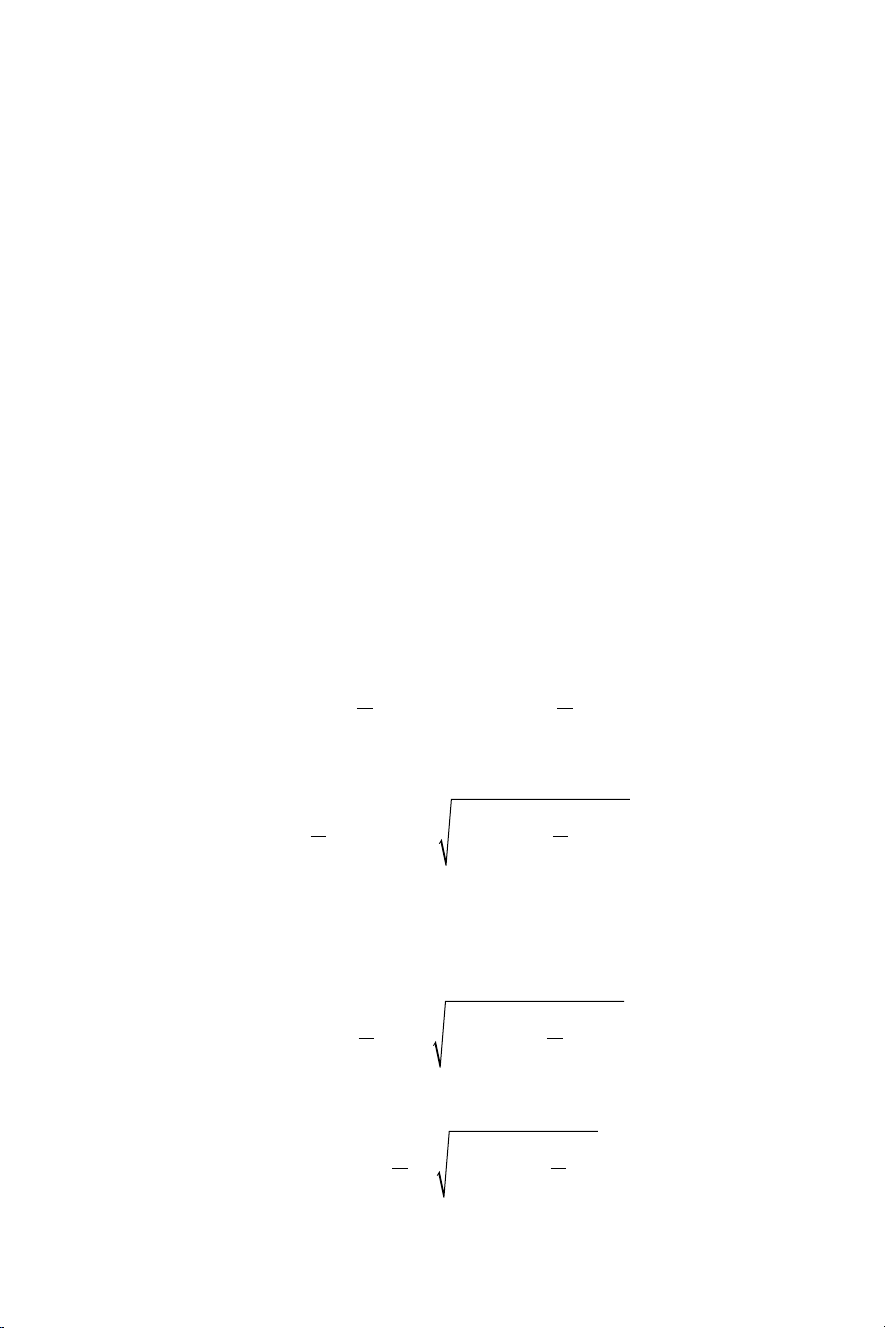
58 Sewing Machines and Processes
AB
22
22
22
nc
nc
22
22
rl
22
FIGURE 4.1 Mechanism of the needle motion.
Based on the constant length of AB, the following expression can be written for the
relation of points A and B coordinates:
lyyxx
2
AB
(4.4)
Substituting Equation (4.3) into Equation (4.4) yields
lr yr
2
si
B
os
(4.5)
which has two solutions:
rylr
si
B
2
os
2
(4.6)
One of these solutions corresponds to the position of point B under point O and the
other corresponds to the position of point B over point O. In the current case, the
motion law of point B, the needle eyelet E and the needle top T can be expressed by
the following solution:
yr lr
sin
B
2
cos (4.7)
2
The upper limit position of the needle (point B) corresponds to a vertical coordinate:
yr lr
0
B
sincos (4.8)
2
2
Page 70
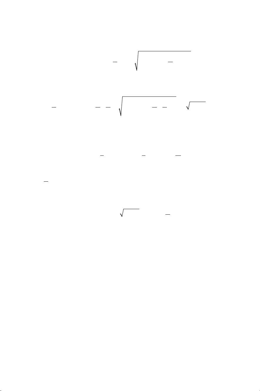
and the bottom limit position is
22
22
lr
2
2
2
BB
59Needle Thread Motion
yrlr r
B
sincos ll
2
2
180
(4.9)
The position at the horizontal state of OA, which corresponds to 90° and 270° of the
main shaft, is located at
yrlr
B
2
90
sincos
22 22
2
2
(4.10)
It is now obvious that the motion law of the needle is not exactly symmetrical relative
to the horizontal axis, because the coordinate of the needle at 90° is not in the middle
of the upper and bottom positions, but is
ymiddlerlrlll
B
1
1
2
l
l
(4.11)
Practically speaking, this means that at the middle of the time of its travel
2
, the needle has a higher position than the geometrical middle of its
90
path:
ymiddlel lr y
22
2
(4.12)
90
This knowledge is important for the analysis of needle thread length because the
different phases of the needle thread motion depend on the position of the needle
eyelet relative to the textile. Equation (4.12) demonstrates that these phases are not
connected with the exact position of the main shaft at 0°, 90°, 180°, 270°, but depend
on the exact times when the needle eyelet crosses the stitch plate and the material. Additionally, the different phases also depend on the thickness of the material
(Figure 4.1).
4.3 THREAD LENGTH REQUIRED FOR CLASS 300 STITCHES
During the motion of the needle from its upper end point until the eye crosses the
material thickness, sewing thread must be delivered [1] ( Figure 4.2). The length of
the thread corresponds to the required length for one complete stitch. Simplied, this
corresponds to stitch length t.
For more accurate information the material thickness and the thread thickness
must be considered, and the vertical position of the interlacement point must also be
known. More detailed information about this correction is provided in Chapter 8.
Page 71

60 Sewing Machines and Processes
Ls
FIGURE 4.2 Required thread length until the needle eye crosses the fabric corresponds to
the length required for one stitch.
FIGURE 4.3 Required thread length after the needle has penetrated the material to the
bottom end position.
The second phase of the needle motion starts when the needle eye crosses the
material (Figure 4.2). From this point until the bottom end position of the needle, it
pulls a loop of two thread pieces through the material (Figure 4.3). For this reason,
the required thread length for this second period can be expressed as the double path
of the needle:
The required length of the sewing thread during this phase is shown in Figure 4.3 as
a dark curve with the number 2.
During Phase 3, the needle moves from the bottom end point upward. After
approximately 2 mm, the needle thread builds a loop (Figure 4.4). This process is
explained in Chapter 3. During this motion of the needle, it is not permissible for the
yy
Bend Bcrossing
,
2
2
(4.13)
Page 72

61Needle Thread Motion
LD
FIGURE 4.4 Loop building phase during which no thread tension is applied.
thread to be pulled up. If it is pulled up, then no loop can be formed and the top of
the gripper is unable to grab the loop to perform the following steps of the process.
For this reason, the ideal diagram for sewing thread consumption is a horizontal line
(Figure 4.4, position 3), which means that no change in the sewing thread is allowed.
Once the tip of the hook grasps the loop (Figure 4.4, position 3), it extends the
loop and moves the needle thread around the assembly with the bottom thread bobbin, its capsule and the hook. This assembly can be considered as a simplied cylinder with diameter D and width B, meaning that a length of
4
2
B
(4.14)
is required in order for the loop to pass over the assembly at the nal stage (Figure
4.5). The rotating hook performs two rotations per one cycle of stitch building. Its
name in German is “Doppel-umlauf-greifer”, which means “hook which performs
two full rotations”. The hook rotates at a constant speed, so the duration of a 180°
rotation from start to nish of Phase 4 corresponds to a 90° rotation of the main shaft
(Figure 4.5). At the end of this phase, the loop has passed over the assembly through
its diameter. At this point, the take-up lever does not start taking up because the loop
is placed at a mechanically indenite place. Depending on the construction of the
bobbin case and the hook’s geometry, the loop can start sliding backward or forward
if, at that moment, tension is applied, because in reality the hook tip is not clearly
formed and remains outside the case, as shown in Figure 4.5. If it slides backward,
then the interlacement with the bobbin thread will not occur, resulting in a missed
stitch. If tension has already been applied and the loop does not start sliding, the
thread will break. For this reason, following Phase 4 completion, a short period
without thread tension is required, as discussed in Phase 5 (Figure 4.6).
During Phase 5, the hook rotates further and moves the thread loop around it
away from the neutral 180° position into a new position, where it is mechanically
and geometrically determined that the thread will slide forward around the capsule
if tension is applied (Figure 4.6). Phase 5 is short as it takes only a few degrees of
rotation. After the end of this phase, the thread take-up lever must work rapidly and
Page 73

62 Sewing Machines and Processes
FIGURE 4.5 Thread loop passes over the hook assembly and increases in length.
FIGURE 4.6 Phase 5 – short rotation of the hook to move the loop outside of the neutral
position at 180°.
Page 74

63Needle Thread Motion
0
Lt
+
must take the complete amount of needle thread through the needle eye and back to
the upper side over the connected textile (Fig ure 4.7). On completion of the cycle,
the curve does not end at the initial point
required, so the curve ends at
, where t=1÷10 mm; however, it is usually in the
0
, because the length of one stitch is
L
range of 2–4 mm for normal textiles. Fig ure 4.7 shows that a large amount of sewing
thread passes through the needle eye once down so that it can go completely around
the bobbin assembly and then pass again back through the needle eye up. This large
amount of friction sets very high and very special requirements on sewing thread for
lock-stitch machines. In order to build a stable loop, such machines must have excellent abrasion resistance and have no unbalanced untwisting moment inside.
4.4 USING LARGER BOBBIN FOR BOTTOM THREAD
The bottom thread bobbin is small and can take a limited amount of thread. For this
reason, the sewing process, especially the embroidery process, is often interrupted
in order to change the empty bobbin. To reduce the number of bobbin changes, some
producers opt to use larger bobbins. The standard bobbin (L size) has a diameter of
26 mm; an XXL bobbin has a diameter of 32 mm and can hold 70% more thread
volume; and the 3XL bobbin with a diameter of 40 mm can hold an additional 70%
more volume [2]. The increased bobbin volume requires an increase in the length of
the needle thread during the stitch formation process (Figure 4.8), which means that
each point of the sewing thread must pass multiple times through the needle eye until
it is placed in the seam.
FIGURE 4.7 Phase 6 – taking the thread out of the bottom area using the thread take-up
lever.
Page 75

64 Sewing Machines and Processes
LL DB
Lm
Lm
Lm
FIGURE 4.8 Required thread length after the needle has penetrated the material to the
bottom end.
The following calculation demonstrates this inuence. Let us assume a bobbin
assembly of diameter D=30 mm and width B=10 mm, and the needle path under the
plate is L2=10 mm.
The complete thread length required to go under the plate and pass around the
boon is
loop
2 (4.14)
2
Assuming for this example that the diameter of the assembly (bobbin, capsule, hook
together, at the stage where the loop is going over) is approximately 30, 35 and 45
mm, then the complete loop length is
loop D,
loop D,
loop D,
10 2301090 (4.15)
30
10 23510 100 (4.16)
35
10 24510 120 (4.17)
45
If these three different machine stitches with a stitch length of l=2 mm are performed, then one point P (Figure 4.8) from the thread passes L
take-up lever to the bobbin through the needle eye and the same number of times
(minus one!, but we ignore this for simplicity) back from the bobbin side to the takeup lever, yielding
m
m
m
/t times from the
loop
Page 76

65Needle Thread Motion
2/
2
100
NLt
until it is placed into one stitch. The different dia meters for these are
times, N
D==35
times, and N
120 times. This calculation demonstrates
D==45
(4.18)
loop
N
D
30
90
2
90
that increasing the bobbin size can reduce the frequency of bobbin changing during
sewing due to the higher volume of bottom thread; however, it increases the friction
cycles of the sewing thread, which has to pass the needle. More friction cycles lead to
higher abrasion of the sewing thread, which leads to a reduction in its nal strength
when it is placed in the seam. More friction cycles per stitch also means higher
energy dissipation, leading to increased heating of the sewing needle [3, 4]. For some
materials and speeds, the needle can reach temperatures higher than 200°C [5, 6]
and the thread and/or the sewing material can start to melt. Melting of the textile
fabrics at the stitch place is mainly an optical and probably a haptic problem, while
melting the sewing thread means interrupting the sewing process with all the resulting negative consequences in reduced productivity, a defective sewing line and bad
optics on the repeated places.
Equation (4.18) and Figure 4.9 show that reducing the stitch length signicantly
increases (inverse proportional) the number of cycles, where one point P from the
needle thread must pass in both directions through the needle eye in order to move
from the bobbin until its nal place (P2) in the seam. To produce stitches with lengths
of 4–6 mm, one point of the sewing thread passes approximately 40–60 times
through the needle eye; for 2 mm stitch lengths, this number increases by 100 times;
and for 1 mm the number increases by around 200 times (Figure 4.9). For such cases,
a fan for needle cooling can be applied if all other possibilities (thread neness, oil,
needle size and type) have been tested.
FIGURE 4.9 Total number of passes of one point of the needle thread through the needle
eye as a function of the stitch length and the hook assembly diameter.
Page 77

66 Sewing Machines and Processes
Bm
28
3t
Lt
2t
FIGURE 4.10 Required thread length for Phase 4 – looper holds the loop – for Classes 100,
400, 500 and 600.
4.5 THREAD LENGTH REQUIRED FOR CHAIN STITCHES
The required needle thread length for stitch building chain stitches can be obtained by
analogous analysis of the single phases, such as those performed for the lock stitch. Up
to Phase 3, the required length for loop building is unchanged, and Figure 4.10 shows
the same values and appearance as for a lock stitch. After preparation of the loop of
the needle thread, the tip of the hook (looper) takes the loop, increases its length and
holds it (Figure 4.10). The circumference of the looper is signicantly lower during
the assembly of the bobbin, capsule and hook for a lock stitch by approximately 10
mm (Eq. 4.19), compared to the loop for a lock stitch at 80–120 mm:
LD
chain4
,
m
(4.19)
For a Class 400 two-thread chain stitch, after that in the needle loop is inserted the
loop of the bottom thread and the available length from Phases 2 and 4 have to be
taken out during Phase 6 ( Figu re 4.11). Note that here, Phase 5 of the lock stitch process is not needed for chain stitches.
For Class 100 stitches and some of the subclasses of Class 500, the required
thread is signicantly different. After the needle thread is placed over the looper
and the needle leaves the opening of the perforated material, the material starts its
transport process. The complete textile material is moved one stitch step ∆t forward
(Figure 4.12). During this step, the required length of the needle thread has to be
pulled out. For Class 100 stitches, this corresponds to approximately three times the
stitch length
one thread segment ∆t over the material and two segments
:
3
Class5 100
,
(4.20)
as part of the loop
from the bottom side (Figure 4.12).
For subclasses of Class 500 – over-edge chain stitch or overlock – where the
needle thread covers the edge, this length increases with the thread length required
to cover the edge with width B:
Page 78

67Needle Thread Motion
LtBK
FIGURE 4.11 Required thread length for Phase 6 – needle thread is taken out of the bottom
area – for Classes 400 and 600.
FIGURE 4.12 Required thread length after the needle penetrates the material to the bottom
end.
where B is the width of the overlock stitch and is around 4–5 mm. The coefcient K
is larger than 1 and, considering the fact that the thread is not exactly perpendicular
to the edge of the material because it must meet the next one needle stitch opening, it
is placed on the hypothenuse of the triangle based on the stitch length and the seam
width. More detailed calculations on these lengths are provided in Chapter 8.
Class5 500
,
32
(4.21)
Page 79

68 Sewing Machines and Processes
Note from Figure 4.12 that the required needle thread does not return to the point
L0 because almost the complete length of the thread remains under the fabric. Sliding
between the needle thread and the needle eyelet is signicantly reduced and limited mainly in the direction of the delivering thread. Thus, one point of the thread
passes the needle eye up to three to ve times, but not 50 or more times as for the
lock stitch. For this reason, the requirements of the sewing thread for chain stitches,
especially for Classes 100 and 500, are signicantly reduced compared to those for
lock stitches. For these stitch classes, sewing threads based on multilament yarns
without or with a very low twist and not very high strength can be used. The thread
needs to be of a sufciently high strength to be pulled through the needle eye and all
guiding elements during the extension of the loop in Phase 5.
4.6 CONCLUSION
The analysis of the motion and the required length of the needle thread for different
stitches demonstrates very different behaviors of the needle thread for the different
classes. Building the lock stitch with a rotary hook and a large capsule requires a
long length of thread to be taken multiple times through the needle eye, placing serious demands on the thread regarding its strength and friction resistance. The large
number of friction cycles causes additional needle heating, which can interrupt the
sewing process. On the contrary, the building of chain stitches requires less thread
length to pass the needle eye, needs simplied compensation and tensioning mechanisms and allows the use of a larger variety of threads as sewing threads.
REFERENCES
1. Kosev K. Development of knitting and sewing machines (Bulgarian: Proektirane na
trikotajni i konfektionni mashini), Technika, Soa, Bulgaria, 1979.
2. Rödel H. Analyse des Standes der Konfektionstechnik in Praxis und Forschung sowie
Beiträge zur Prozessmodellierung. Als Ms. gedr. Aachen: Shaker, 1996.
3. Aychilie DB, Kyosev Y. Sewing needle heating: A review on the research regarding
causes, effects and methods for its reduction. Vitebsk: Republic of Belarus, p. 050007.
4. Mazari A, Bal K, Havelka A. Prediction of needle heating in an industrial sewing
machine. Text Res J. 2015; 86: 302–310.
5. Rödel H. Kettenstiche. In: Gries T, Klopp K (eds) Füge- und Oberächentechnologien
für Textilien. Berlin: Springer, 2007, pp. 14–18.
6. Rödel H. Kettenstiche. In: Gries T, Klopp K (eds) Füge- und Oberächentechnologien
für Textilien. Berlin: Springer, 2007, pp. 14–18.
Page 80

5
Sewing Needles
Daniela Sofronova
1
5.1 INTRODUCTION
The invention of the sewing needle dates back to ancient times. Evidence of its use
has been found in archaeological discoveries dating as far back as the Palaeolithic
era. Eyed needles made of bone, ivory, and antler have been discovered in Eurasia
(d’Errico, 2018) (Figure 5.1). The discovered artefacts have proved that people were
sewing close-tting garments to protect themselves from the environmental conditions (Wang, 2020).
Advancements in metalworking techniques led to the creation of a more rened
and durable needle design compared to earlier needles that were made from bone or
ivory. However, the exact timeline and circumstances of the sewing needle’s design
remain uncertain, as historical records from this era are limited. The oldest iron
needle was found in Germany and dates back to the 3rd century BC (Valiulis, 2014).
This phenomenon is explained by the corrosion of metallic needles, as they degrade
over time and are often found in poor condition, even those manufactured during the
19th century.
The invention of the sewing machine gave rise to the development of the sewing
machine needle. In 1755, Wiesenthal developed a two-point needle, which was later
used by Madersperger (Grifths, 1992). Nowadays, it is applied in modern industrial
machines for sewing shank buttons or for imitating handmade seams. Around 1810,
Balthasar Krems, a German hosiery maker, used a needle, for the rst time, which
had the eye moved close to the point, but he did not patent or commercialize his
invention (McLoughlin, 2017). Later in 1835, the American inventor Walter Hunt
developed the rst model of the lock-stitch sewing machine working with an eyepointed needle and two threads. Initially, he did not patent his mechanical device.
This technology was revolutionary at that time. In 1845, attempting to imitate hand
sewing, Elias Howe also came up with the idea of applying two threads for stitch
forming using a shuttle and curved needle with an eye near the point (Mossoff, 2011).
Hunt submitted his initial application for his sewing machine in 1853, shortly before
Howe. This led to a court case. According to the Supreme Court, Hunt’s invention
was made before Howe’s machine and even though the patent ofce identied Hunt’s
pre-existence, it did not give the patent to him. The reason was that he had not completed the necessary paperwork for the patent before Howe’s application had been
1
With thanks to Groz-Beckert Company, Germany, for providing access to the image and content
materials.
DOI: 10.1201/9781003293071-5
This chapter has been made available under a Creative Commons Attribution
(CC-BY) 4.0 International license.
69
Page 81

70 Sewing Machines and Processes
FIGURE 5.1 Sewing needle made from bone found at Gourdan Cave, Haute-Garonne,
France. It belongs to the Western European Magdalenian culture (c. 17,000 to c. 10,000 years
ago) of the Late or Upper Palaeolithic industry (c. 50,000/40,000 to c. 10,000 years ago).
(Descouens, 2016)
submitted. Hunt received public recognition for his invention, but Howe received a
formal patent for the machine. To the contemporary observer, this invention may
appear straightforward, but it served as the cornerstone for the global mechanization
of the sewing industry.
The needle is one of the most important parts of the sewing machine as the sewing process would be not possible without it. Its primary function is to penetrate the
materials that are to be joined, thereby creating a stitch hole. At the same time, the
needle guides the sewing thread through the materials and supports it during loop
formation. The stitch is formed between the needle and the looper/hook or between
the needle and the bobbin thread. As industrial sewing machines can perform up to
10,000 stitches per minute, sewing needles must be produced with the highest precision. A general view of a sewing needle is shown in Figure 5.2.
5.2 ELEMENTS OF A SEWING NEEDLE
Figure 5.3 shows the construction of a sewing needle with its basic components
designated. A needle has the following elements: butt, shank, cone, blade, scarf,
eye, and point. When looking at a needle, the viewing direction is always from the
FIGURE 5.2 Machine sewing needle. (Groz-Beckert, 2024)
Page 82

71Sewing Needles
FIGURE 5.3 Sewing needle elements. (Groz-Beckert, 2024)
shank towards the point, the long groove facing downwards. This way, the directions “bottom”, “top”, “right”, and “left” are dened. When angles are indicated, the
long groove is set to 0° for reference. Degree values increase counterclockwise, i.e.
“right” is at 90°, “top” is at 180°, etc.
Each needle can be divided into two sections:
• Clamping part – consists of shank and cone;
• Working part – includes blade and point.
The shank extends from the butt to the cone. Most needle systems have the same
shank diameter for all sizes. For some needle systems, the shank diameter gradually
changes depending on the needle size. On the sewing machine, the shank enters the
needle bar (hole or clamp), where it is usually xed by a screw. The needle size and
the producer’s logo are stamped into the shank.
The diameter, length, and possible special shapes are determined by the sewing
machine. The following are shank types:
• Round
• Flat
• Flattened at the butt
• Grooved
• Notched
• Threaded
• Reduced
Page 83

72 Sewing Machines and Processes
The two most important types are the round and at shanks, and the round shank is
the most common.
The transition from shank to blade is called a cone. Its length depends on the ratio
of the shank diameter to the blade diameter as well as on the angle or radius of the
cone.
The blade is the part of the needle between the end of the cone and the beginning
of the eye. Different types exist depending on the manufacturing procedure.
There are two grooves in a needle: long and short. The long groove runs from the
end of the shank to the beginning of the eye. It always faces the threading direction
and, in most cases, is the same width as the eye. When the needle penetrates the
material or when the loop is enlarged by the looper/hook, the long groove protects
the thread from severe frictional contact with the material. The short groove is opposite the long groove, facing the looper/hook. It also protects the thread from severe
frictional contact with the material.
The scarf is a recess in the needle blade that permits the unobstructed movement
of the looper/hook and reliable catching of the loop. The depth of the scarf is the
distance between the blade diameter and the lowest point of the scarf.
The opening in the needle blade, through which the thread is inserted, is known
as the eye. It can be produced in different forms and sizes.
The construction of the sewing needle ends with a point, which is extended from
the beginning of the eye. Its position can either be centric or eccentric.
5.3 PRODUCTION OF SEWING NEEDLES
The manufacturing of sewing needles requires precision techniques to produce highquality products that meet the demands of various sewing applications. The main
properties of sewing needles are durability, exibility, and resistance to corrosion.
There are several steps in the manufacturing of sewing needles (Figure 5.4). It
takes over 100 operations to produce a sewing needle in its nal form.
The rst step in the manufacturing process is the selection of raw wire material.
Sewing needles are usually produced from high-carbon steel having high strength
and hardness. At the swaging step, the wire is cold forged to the diameter of the
needle blade. Using a series of dies and punches, the scarf and the eye are produced.
At the milling step, the long groove is produced with a rotating tool. Following the
die pressing operations, the resulting barbs and most of the material around the point
are removed by grinding. Hardening is a heat treatment operation that provides the
needle with mechanical strength and durability. The process of smoothing is responsible for removing any sharp edges especially at the groove and around the eye. It is
usually carried out using a chemical process. Any detected bends that might occur
as result of the previous steps are measured and xed before the needle goes to nal
operations. Finally, the point is precisely shaped and polished. All industrial needles
are plated to protect them from corrosion, improve wear, and reduce friction during
penetration into the material (Vedat, 2014). Depending on the type of plating, mainly
its thickness, the nal shape of the point is produced after plating the coated layer.
Page 84

73Sewing Needles
FIGURE 5.4 Manufacturing process of sewing needles.
Needle surface plating is carried out using electrolysis. The materials used are
nickel, chromium, or titanium nitride (TiN). Standard sewing machine needles
are chrome plated and can be identied by their silvery surface (Figure 5.5a). The
chrome layer provides protection against wear and corrosion. It also gives the needle
a smooth surface that protects the material and thread. Chrome needles can be used
for all standard applications.
High-performance needles usually have a titanium nitride coating and can be
distinguished from standard needles by their “golden” appearance (Figure 5.5b). The
needles have a homogeneous, hard, and smooth surface and a signicantly higher
resistance to wear and point damage than standard needles. However, the higher
stability of the needle cannot be achieved using this type of coating because its
geometry corresponds to that of a chrome-plated needle. The improved wear resistance leads to a uniform and high-quality seam and a longer needle life, resulting in
increased productivity.
There are also non-metal needle coatings such as polytetrauoroethylene (PTFE).
This type of coating reduces friction and prevents textile threads from sticking to the
FIGURE 5.5 Needle coating: (a) chrome and (b) titanium nitride. (Groz-Beckert, 2024)
Page 85

74 Sewing Machines and Processes
5.4.1 nEEdlE typEs aCCording to nEEdlE systEm
5.4.2 nEEdlE typEs aCCording to sizE (nm)
needle surface. They are suitable for thick fabrics produced from synthetic threads.
PTFE-coated needles have less resistance to friction than TiN-coated needles.
A common issue during machine sewing is the needle heating generated as a
result of the frictional loss formed by the needle’s penetration into the material.
Needle heating can cause various problems that affect the sewing process, thus the
temperature must be maintained under 140°C (Dal et al. 2014). Cooling down of
the needle is due to convection, conduction, and radiation. Most heat loss is through
conduction whereby the heat is carried away from needle to the needle bar. When the
machine is working, about 30% of the heat is cooled down by convection. Needles
with a black-matt surface are cooled down through radiation more than those with a
highly polished surface (Vedat, 2014).
5.4 NEEDLE IDENTIFICATION
To distinguish between different sewing machine needles, each needle has a specic
designation, which consists of three or four components: needle system, point style,
needle size, and coating.
Different classes of sewing machine require a specic size and type of needle. A
group of needles that belong to a specic sewing machine class is called a needle
system. It indicates the basic features of the needle such as shank diameter, length
from butt to eye, number of grooves, and point length, that determine which machine
the relevant needle ts.
The needle system can either consist of numbers (e.g. 134, 134-35) or a combination of numbers and letters (e.g. UY 128 GAS, DBX1). Designation of the same
needle can vary between producers. Some systems have two groups of numbers
separated with x (62x59); other systems use another type of format (1000H). For the
convenience of users, some manufacturers write the needle system in different ways
(Figure 5.6).
It should be noted that the numbers in the needle system may not always directly
correspond to the physical dimensions of the needle.
Before 1940, there were no uniform size designations for home or industrial needles.
Each manufacturer adopted their preferred sizing system, resulting in over 40 different systems. After 1940, needle sizes were standardized, leading to the adoption of a
new needle designation method by most manufacturers.
The needle size indicates the needle according to the diameter of the needle blade
in the numeric metric system Nm. It is derived by multiplying the diameter in millimetres by 100. For example, if the diameter of the needle blade is 0.55 mm, then
the needle size is Nm55. Many countries around the world use the numeric metric
system for sewing needles, including most European countries, Australia, and New
Page 86

75Sewing Needles
FIGURE 5.6 Needle designation. (Groz-Beckert, 2024)
Zealand. Additionally, the numeric metric system is commonly used in countries
that have adopted international standards for sewing and textile manufacturing.
Needle sizing generally ranges from 35 to 200, but the most widely used needles are
Nm50, 60, 70, 80, 90, and 100. Most manufacturers stamp the size on the shank of
the needle.
Some countries still use the traditional sizing systems based on numbers or letters, such as the United States, Canada, the United Kingdom, Japan, and China.
For example, in the United States, sewing needles are often labelled with numbers
such as 8, 10, and 12, while the United Kingdom uses letters such as A, B, and C.
Conversion charts are available for needle size designations. Sometimes, the needle’s
metric number is appended with its number entered by Singer. For example, a needle
Page 87

76 Sewing Machines and Processes
5.4.3 nEEdlE typEs aCCording to nEEdlE point
with Nm70 is written as 70/10. Therefore, a needle with a diameter of needle blade
0.7 mm corresponds to a needle with number 10 according to Singer’s designation.
Sewing needles have different point styles, which are needed to meet the requirements of different textile materials and leather. Point styles are divided into cloth
points (round or set points) and cutting or leather points (Figure 5.7).
Needles with cutting points have sharp tips like blades to cut the material when
going through it. They are mainly used for sewing leather. The leather worker’s trade
is one of the oldest in the world. In the past, the only priority for seam construction
when combining leather pieces was its durability. The appearance of the seam was
not important, but nowadays both indicators have equal signicance.
Cloth points are particularly suitable for knitted and woven fabrics and displace
the threads of the structure. The standard point in the needle system is not normally
indicated in its designation, for example, the “R” point for all needles used in lockstitch machines and the “RG” point for all needles used in chain-stitch machines.
Each sewing needle producer has their own designation according to the point style.
5.4.3.1 Cutting Points for Leather Processing
The most-used cutting points for sewing needles total nine. The following examples
are according to Groz-Beckert Company.
1. Needle with cutting LR point (narrow reverse twist point)
Needles with an LR point provide cuts at a 45° angle according to the threading
direction. This type of needle is suitable for short to medium stitches as the stitch
holes are easily visible. The sewn thread is slightly elevated. Depending on the
leather, the stitch formation is slight to medium slanted. This type of needle is shown
in Figure 5.8a.
FIGURE 5.7 Needles with (a) cutting point and (b) cloth point. (Groz-Beckert, 2024)
Page 88

77Sewing Needles
Needles with LR cutting points are used for decorative lock-stitch seams in soft to
medium-hard leather and nearly all common types of leather used in the production
of shoes, leather garments, upholstery, bags, belts, and car seats.
2. Needle with cutting LL point (narrow twist point)
Needles with a cutting LL point have a cutting angle of 135° depending on the
threading direction (Figure 5.8b). A straight stitch formation is produced and the
stitch holes are lled. They are used in the production of shoes, bags, car seats, and
upholstery, where straight seams with a continuously closed seam appearance are
required. They can be used on almost any type of leather.
3. Needle with cutting D point (triangular point)
Needles with a cutting D point cut leather in a prominent triangular shape (Figure
5.9a). The stitches have a straight appearance and the stitch holes are relatively large.
The possible stitch step is medium to short.
The application eld for needles with a cutting D point are straight sewing on
hard and thick leather as well as cartons. Belts, suitcases, heavy shoes, and plastics
can be sewn with this type of needle.
4. Needle with a cutting DH point (half triangular point)
Needles with a cutting DH point have a half triangular point and leather is cut in a
medium triangular shape (Figure 5.9b). The stitches have a straight appearance and
the stitch holes are relatively large. They are suitable when medium to long stitches
are required.
FIGURE 5.8 Needles with (a) LR cutting point and (b) LL cutting point. (Groz-Beckert,
2024)
Page 89

78 Sewing Machines and Processes
FIGURE 5.9 Needles with (a) D cutting point and (b) DH cutting point. (Groz-Beckert,
2024)
Needles with a cutting DH point are used in the production of upholstery, bags,
shoes, and tarpaulins, when straight seams must be produced. They are suitable for
medium-hard and hard leathers.
5. Needle with a cutting SD point (small triangular tip)
The cutting SD point is round with a small triangular tip cutting edge. Thus, leather
can be cut in a slightly triangular shape (Figure 5.10a). The stitch has a straight
appearance and is of short to medium length.
The application eld for needles with a cutting SD point is in producing almost
straight and inline stitches. They can be used for soft leather and multidirectional
applications. For example, this type of needle is appropriate for shoes, accessories,
leather garments, ne leather goods, foils, and laminated materials.
6. Needles with a cutting P point (narrow wedge point)
Needles with a cutting P point cut the material at a 0° angle to the threading direction (Figure 5.10b). Due to its heavily slanted stitch formation, it creates a prominent
decorative stitch on thick and hard leather. The sewn thread lls the stitch holes as
short stitches are possible.
This type of needle can be used for producing decorative stitches and it is well
suited for heel and closed seams or for seams with high power transmission. For
example, a needle with a P cutting point is appropriate for leather products with the
highest tensile strength, such as shoes, belts, and upholstery.
Page 90

79Sewing Needles
FIGURE 5.10 Needles with (a) SD cutting point and (b) P cutting point. (Groz-Beckert,
2024)
7. Needles with a cutting PCL point (narrow wedge point – with left twist
point groove)
A needle with a cutting PCL point is a variation on the needle with a cutting P point
(Fig ure 5.11a). It cuts at a 0° angle to the threading direction and the stitch appearance is the same as the cutting P point needle. The abbreviation CL in the needle’s
name shows that it has a left twisted point groove for a rotary hook and is placed
on the right side of the needle. The twisted point groove prevents the sewing thread
from being pulled over the cutting edge and thus being damaged when the needle is
in its upward motion. The thread is placed in the twisted point groove.
This type of needle is suitable for producing decorative stitches and for heel and
closed seams in shoes, belts, accessories, and upholstery.
8. Needle with a cutting S point (narrow cross point)
Needles with a cutting S point cut at a 90° angle to the threading direction (Figure
5.11b). The stitches have a straight inline appearance, but the stitch holes are long and
visible. The stitch lengths can be medium to long.
The application eld for these needles includes seam production with straight
stitches. They are suitable for most leathers, for seams that are tight to the edge, and
for seams where the top and bottom sides are visible (e.g. handles of bags, reversable
belts). This type of needle is appropriate in the manufacture of shoes, belts, accessories, car seats, and upholstery.
9. Needle with a cutting R point (standard round point)
Needles with a cutting R point have a standard round point just like needles with a
cloth point without the cutting effect (Figure 5.12). The stitches have a medium to
Page 91

80 Sewing Machines and Processes
FIGURE 5.11 Needles with (a) PCL cutting point and (b) S cutting point. (Groz-Beckert,
2024)
long length and are almost straight, yet irregular. The stitch appearance is variable
and the stitch holes are irregular and inconsistent.
These types of needles are used on soft leather, embroidery, and for multidirectional applications. Application examples include sports shoes, garments, car seats,
and upholstery, and on foils and laminated materials.
FIGURE 5.12 Needle with R cutting point. (Groz-Beckert, 2024)
Page 92

81Sewing Needles
5.4.3.2 Cloth Points for Processing Textile Fabrics
All textiles, whether woven, warped, felted, or knitted, are sewn with a specic
needle point shape to suit their structure. The right choice of point has a signicant effect on the nished sewing results. There are about 20 different round point
needles, and the most commonly used are as follows:
1. Needle with a cloth RS point (sharp round point)
Needles with a round RS point are standard for blind-stitch needles and Schifi
needles used in embroidery production as well as for lock-stitch operations when
precise stitch sequences are required. The RS point is sensitive and is susceptible to
damage (Figure 5.13a).
This type of needle is used in the production of blouses, shirts, ne skirts, trou-
sers, and for Schifi embroidery.
2. Needle with a cloth R point (standard round point)
The application eld for needles with a cloth R point includes all kinds of lock-stitch
applications, particularly for woven fabrics, leather and articial leather, or coated
fabrics, and for sewing shirts, trousers, and shoes (Figure 5.13b).
3. Needle with a cloth RG point (round point with slightly rounded tip)
Needles with a cloth RG point are standard for the chain stitch and embroidery in the
production of woven and knitted materials and buttons, and embroidery on all kinds
of material using multi-head embroidery machines (Figu re 5.14a).
FIGURE 5.13 Needles with (a) cloth RS point and (b) cloth R point. (Groz-Beckert, 2024)
Page 93

82 Sewing Machines and Processes
4. Needle with a cloth FFG point (light ball point)
Needles with a cloth FFG point are suitable for sewing knitted or woven fabrics, such
as T-shirts, underwear, ne sweaters, jeans, and workwear (Figure 5.14b).
5. Needle with a cloth FG point (medium ball point)
The application eld for needles with a cloth FG point is medium to coarse woven
fabrics, coarse knitwear fabrics, and woven and knitted fabrics with elastomeric content (Figure 5.15a) in the production of jeans, sweaters, lace, and Schifi embroidery.
6. Needle with a cloth G point (heavy ball point)
Needles with a cloth G point are convenient for coarse and open-structured fabrics
and coarser materials with elastomeric content. Sports and medical bandages, cardigans, pullovers, and lace can be produced with this type of needle (Figure 5.15b).
7. Needle with a cloth SKL point (special ball point)
The application eld for needles with a cloth SKL point includes warp knitted fabrics with a high elastomeric content for sewing corsetry, shapewear, foundation garments, and orthopaedic clothes (Figure 5.16a).
8. Needle with a cloth TR point (extra heavy ball point)
Needles with a cloth TR point are used for Schifi embroidery to produce lace, curtains, and tablecloths (Figure 5.16b).
FIGURE 5.14 Needles with (a) cloth RG point and (b) cloth FFG point. (Groz-Beckert,
2024)
Page 94

5.5.1 nEEdlE typEs aCCording to nEEdlE shapE
FIGURE 5.15 Needles with (a) cloth FG point and (b) cloth G point. (Groz-Beckert, 2024)
5.5 ADDITIONAL NEEDLE TYPES
There are two different kinds of sewing machine needle according to its shape:
• Straight needles for chain-stitch and lock-stitch machines;
• Curved needles for blind-stitch and overlock machines.
83Sewing Needles
Examples of both types are presented in Figures 5.17 and 5.18.
Needles are also distinguished by the number of long grooves: lock-stitch needles
have one groove and chain-stitch needles have two grooves.
FIGURE 5.16 Needles with (a) cloth SKL point and (b) cloth TR point. (Groz-Beckert,
2024)
Page 95

84 Sewing Machines and Processes
5.5.2 nEEdlE typEs aCCording to stylE typE
5.5.3 nEEdlE typEs aCCording to ECCEntriC point
5.5.4 nEEdlE typEs aCCording to flat shank
FIGURE 5.17 Example of a straight needle. (Groz-Beckert, 2024)
FIGURE 5.18 Example of a curved needle for the blind stitch. (Groz-Beckert, 2024)
There are many needle types and versions suitable for different machines and used
for all sorts of applications and stitch types. In total, there are about 5000 different
needle types that differ in their basic form, size, point, or other special features.
Figure 5.19 shows 18 needles with different style types (Table 5.1).
A needle point not exactly aligned with the centre of the needle radius is deemed
eccentric. The eccentricity of the needle point has a specic position and is used to
full different tasks depending on the needle type (Figure 5.20).
For blind-stitch needles, the eccentric point ensures that the needle only stitches
as many bres on the tacking side as is required for a secure seam xing. This way,
the seam remains invisible from the outside.
For linking needles, the eccentric point ensures optimal guidance in the dial
needle. This guarantees exact penetration of the needle into the loop hanging on the
dial needle.
Lock-stitch needles with eccentric points are used if the lock stitch is located
extremely close to the edge of the fabric. Due to the outwardly offset point, the
needle is driven into the outer edge of the fabric. The eccentric point may be positioned differently depending on its task. Examples with different point positions are
shown in Figure 5.21.
Sewing machines that orientate the needle on one or multiple sides of the shank are
at (Figure 5.22). The at shanks are used for angular positioning in the needle bar.
This ensures that the needle is positioned in exactly the same specied angle to the
threading direction after each change. This guarantees a clear position of the needle
in relation to the hook or looper.
Page 96

85Sewing Needles
(Continued)
diameter= blade
–
–
–
diameter
Without shank, shank
Without shank
middle
eye
shank barb
DBxK5
134, 134-35, DBx1,
854 S, 110 D, L 83, 88 –
including bar tacking
and zig-zag
including bar tacking
and zig-zag
DMx13, MY 1072
GS/GHS
STRAIGHT, 292 SP
onwards
1032 B, 2000 A Two points, eye in the
253 C, 660 With hook instead of
stitch
UY 36211 Without an eye with
ornamental stitching,
linking machines
needles in multi-
needle machines
TABLE 5.1
Different Style Type Features in Needle Construction
Style type Needle form Groove Scarf Application Designation Note
A1 Straight Single With Lock-stitch machines,
A2 Straight Single Without Lock-stitch machines,
B1 Straight Double With Chain-stitch machines UY 128 GAS, B 27,
B2 Straight Double Without Chain-stitch machines UY 118 GAS, UY 121
C Straight Single long With Chain stitch STEWART
D Straight Double With Collar and cuff linking 367 S from Nm 130
E Straight Double With(two) Machine for hand
F Straight Without Without Embroidery and
H1 Straight Without Without Used as cast-off
Page 97

86 Sewing Machines and Processes
shank barb
UY 36211 A Without an eye with
UY 36211 B Without an eye
needles in multi-
needle machines
One at on the shank
GS, UY 158
needles in multi-
needle machines
additionally bent in
the curve radius
Flattened shank,
BD/BL
Blade area above the
STEWART CURVED,
eye
bend in the curve
Myers No. 6
leather
radius, blade is also
bent sideways
to the long groove
Curved at right angles
GS
UY 9854 GS, UY 9858
needles and other
thick needles
Style type Needle form Groove Scarf Application Designation Note
TABLE 5.1 (CONTINUED)
H3 Straight Without With Used as cast-off
Different Style Type Features in Needle Construction
H4 Straight Without Without Used as cast-off
M1 Curved Single With Overlock machines UY 154 GAS, UY 8454
M2 Curved Single With Overlock machines UY 162 SDS Two ats on the shank
N Curved Single With Blind-stitch machines 1669 E EO, 251 EU, 29
Q Fully curved Double With(two) No longer produced AMF 1014 Double pointed
R Partially curved Single Without Manual handling of
S Curved Single Without Blind-stitch machines 1828 E Curved needle with
T Curved Double With Mainly bag-closing
Source: Groz-Beckert (2024).
Page 98

87Sewing Needles
FIGURE 5.19 Needles with different style types: (a) A1, (b) A2, (c) B1, (d) B2, (e) C, (f)
D, (g) E, (h) F, (i) H1, (j) H3, (k) H4, (l) M1, (m) M2, (n) N, (o) Q, (p) R, (q) S, (r) T. (GrozBeckert, 2024)
On multi-needle machines, the attened surface also determines the distance or
the position of the needles in relation to each other. For needles with cutting points,
at shanks help seams to appear more uniform.
Page 99

88 Sewing Machines and Processes
FIGURE 5.20 Eccentric point of a sewing needle. (Groz-Beckert, 2024)
FIGURE 5.21 Sewing needle with different eccentric points. (Groz-Beckert, 2024)
FIGURE 5.22 Needle with a at shank. (Groz-Beckert, 2024)
Page 100

89Sewing Needles
Depending on the sewing machine type and the position of the screw in the needle bar, different positions of the shank need to be taken into consideration.
Essentially, the four different positions and designations shown in Figures 5.23
and 5.24 are
• FM – at shank on long groove site (0° to threading direction);
• FR – at shank on the right side (90° to threading direction);
• FK – at shank on the opposite side of the long groove (180° to threading
direction);
• FL – at shank on the left side (270° to threading direction).
It should be noted that there are possible exceptions in certain systems and with
certain manufacturers or other positions/angles or notched shanks without a specic
description.
FIGURE 5.23 Needle with different positions on the at shank. (Groz-Beckert, 2024)
FIGURE 5.24 Sewing needle with different positions on the single at shank. (Groz-
Beckert, 2024)
 Loading...