

Page 1
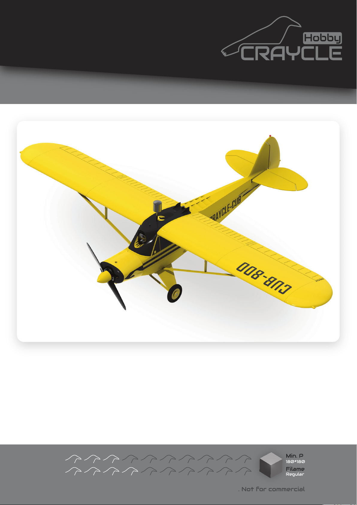
User Guide
Designed By: Cemal ÖZÇELİK
Version: 2.0
Release Date: 04.05.2024
PDF Updated: 16.07.2025
CraycleCub
www.craycle.com
General Specifications
Length
Wingspan
Print Weight
Flying Weight
Wing Area
Wing Loading
Airfoil
Maker Skill
Pilot Skill
© 2024 Craycle Hobby. Copies allowed for personal use only. Not for commercial use.
: 510
: 800 mm
: 253 g
: 440 g
: 9.16 dm2
: 48 g/dm2
: USA 35B
mm
inches
20
31.5 inches
8.9 oz.
18.3 oz.
Recommended Setup
Motor
Propeller
ESC
Servo
Battery
4+ Channels Radio System
Analog/Digital FPV systems
: 2204/5/6 1500/2500 kv
: 5/6/7” - 2/3/4 Blade
: 15-30A
: 4 X 9
: 2s-4s 850-2200 mAh
g
Min. Printer Size
180*180*180 mm
Filament
Regular PLA
Page 2
Equipments
36 mm
150 mm
50 mm
www.craycle.com
Optional EquipmentsNecessary Equipments
• Minimum 4ch Radio System.
• 2205 2300Kv Motor.
• 30A ESC.
• 4pcs 9grams Servo.
• 1500mAh 3S Lipo.
• 6045 Propeller
• Medium CA Glue.
• Y cable for Aileron servos.
• 2 mm Self-Tapping Screws
• 2pcs 100, 2pcs 300, Ø1mm Pushrods.
• PLA - TPU - PetG Filaments.
• Adjustable Pushrod connectors.
• Strong Pliers to prepare landing gear.
• Z bend tool.
• Aileron Angle Meter
• Servo Tester.
• Servo Plug Connectors.
• Screw Driver set.
• Sprey Paint.
• Model stand.
• Lipo Alarm.
• Digital or Analog FPV System.
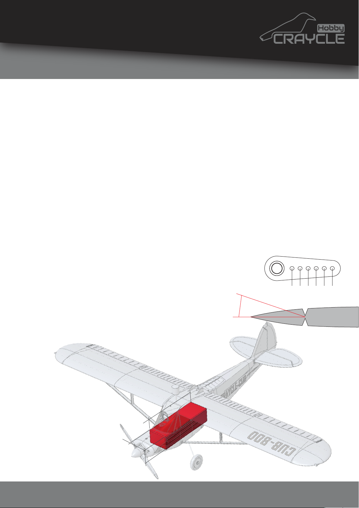
CG position
You can see the marked point under the wing.
Pushrods
You can use 1 mm steel wire.
Wings: 2 pcs 100 mm / Tail: 2 pcs 300 mm
Servo Horn Connection Holes ->
Ailerons: 4. hole / Elevator: 3. hole / Rudder: 3. hole
Flap Movements (X)
Ailerons: 12mm / Elevator: 10mm / Rudder: 10mm
Radio Settings for the Servos
Expos: 35%
Rates: 75%
Payload/Lipo Dimensions
50x36x150mm
1 2 3 4 5 6
x
© 2024 Craycle Hobby. Copies allowed for personal use only. Not for commercial use.
Page 3
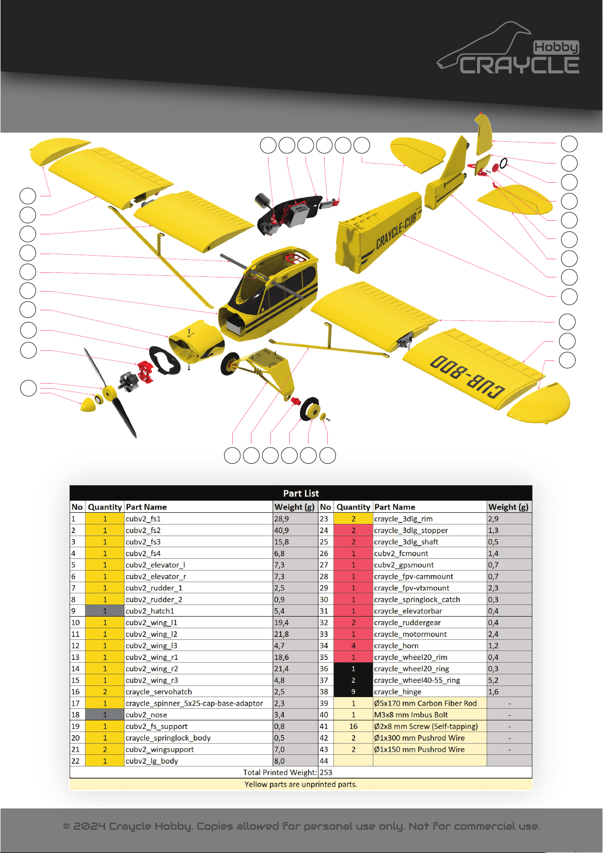
Part List
www.craycle.com
15
14
13
44
19
2
1
18
33
17
28 29 9 20 30 6
7
8
36
35
32
31
5
4
3
10
11
12
22 21 25 37 23 24
© 2024 Craycle Hobby. Copies allowed for personal use only. Not for commercial use.
Page 4
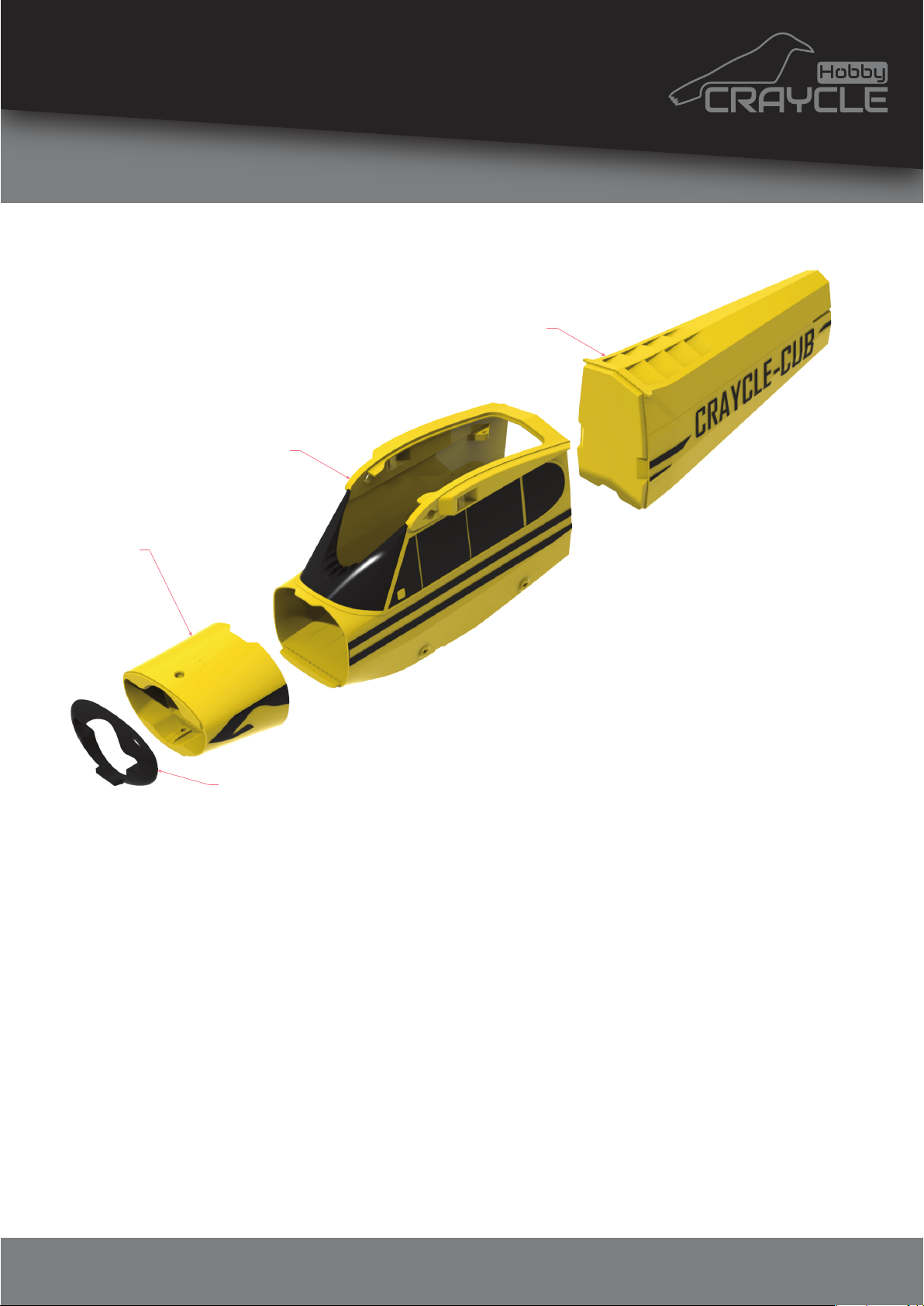
1
Assembly
fs2
www.craycle.com
fs3
fs1
nose
STEP 1
Glue the "lipo_mount" part to "fs2", then glue the
"fs1-nose-fs2-fs3" parts together using CA glue. You can insert
the “craycle_pim” parts into their slots on the fuselage parts to
facilitate assembly.
Avoid spraying the accelerator directly onto the CA glue! Spray
on first piece and wait for 15 seconds to dry it. Then you can
aply glue on the other piece and put the pieces together.
Note: Avoid excessive use of glue.
© 2024 Craycle Hobby. Copies allowed for personal use only. Not for commercial use.
Page 5
2
www.craycle.com
Assembly
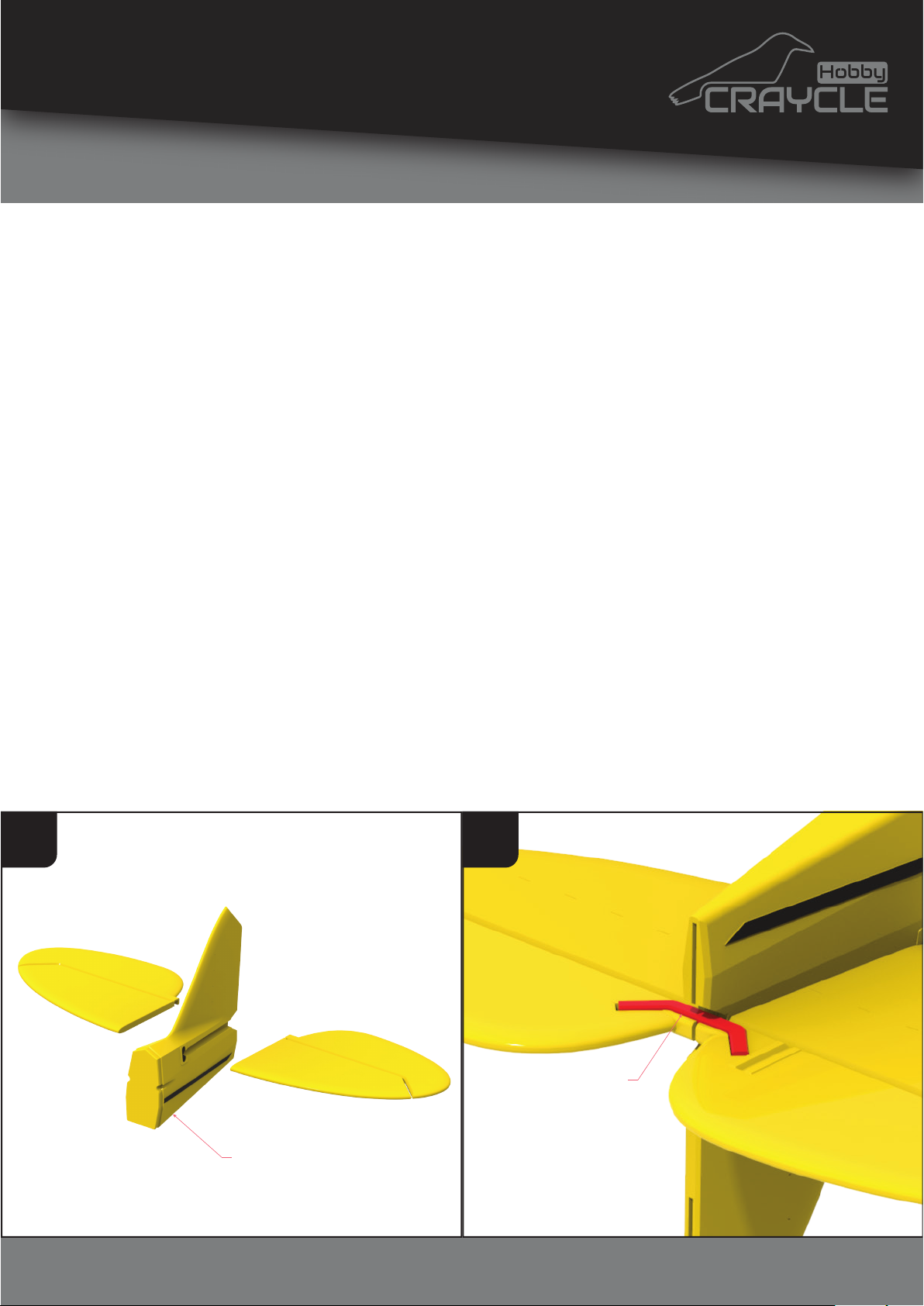
STEP 2
Glue the "fs4" - “elevator_r” - “elevator_l” parts together. Make
sure that the elevators are 90 degrees to the rudder.
Carefully glue the “elevatorbar” part into the slot under the
elevator parts. The elevator bar will distribute all the force to
both sides.
It’s okay there is a small gap between elevator_r and elevator_l.
The elevator bar will handle the mechanism. Please avoid the
excessive usage of glue.
Carefully use sprey accelerator on this step. Avoid spraying the
hinge slots. This makes hinge installation difficult.
1 2
elevatorbar
fs4
© 2024 Craycle Hobby. Copies allowed for personal use only. Not for commercial use.
Page 6
3
Assembly
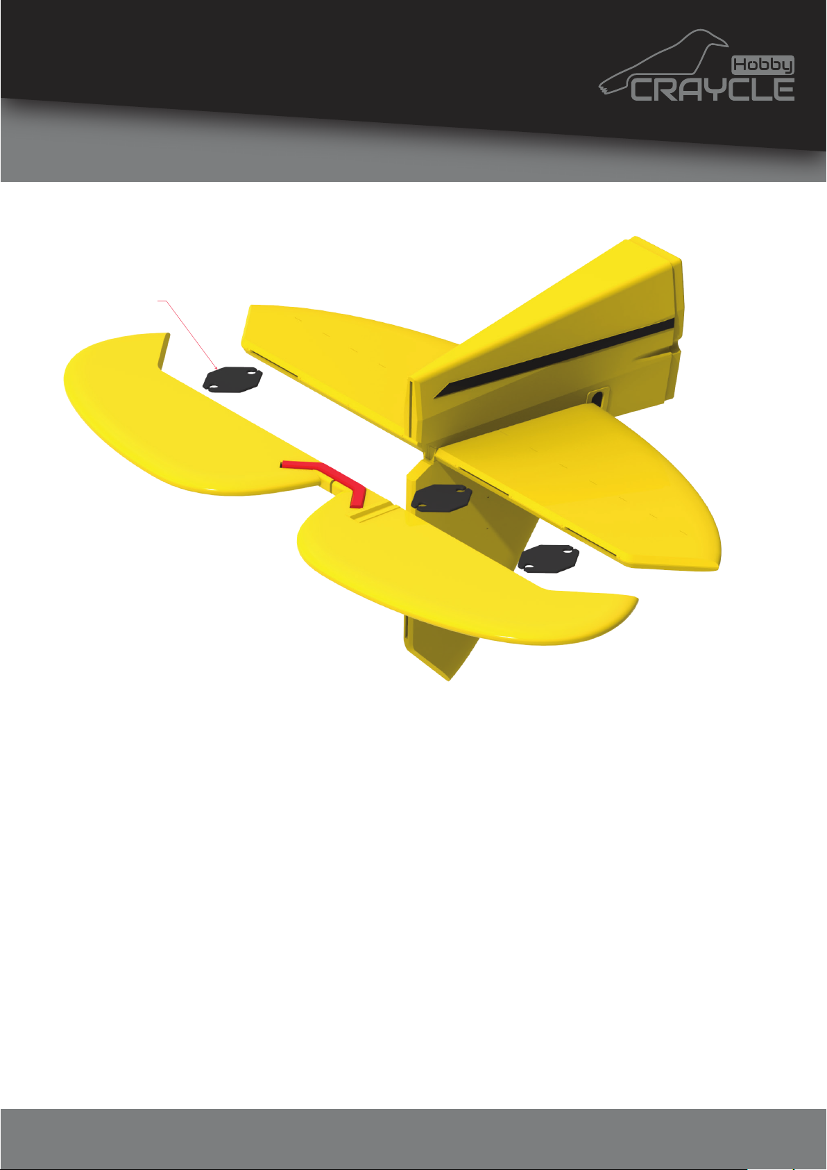
hinge
www.craycle.com
STEP 3
Release the elevator flaps from the elevator by breaking it’s tiny
connections.
Reassemble and glue the flaps using TPU hinges or CA hinges
that you prepared by using Hinge Maker Tool (Available on
craycle.com).
Note: The CA accelerator sprayed to stick the elevator may have
contaminated the hinge slots! Take your time, apply the glue
onto the hinges one by one and insert into the slots on the flap
first.
© 2024 Craycle Hobby. Copies allowed for personal use only. Not for commercial use.
Page 7
4
www.craycle.com
Assembly
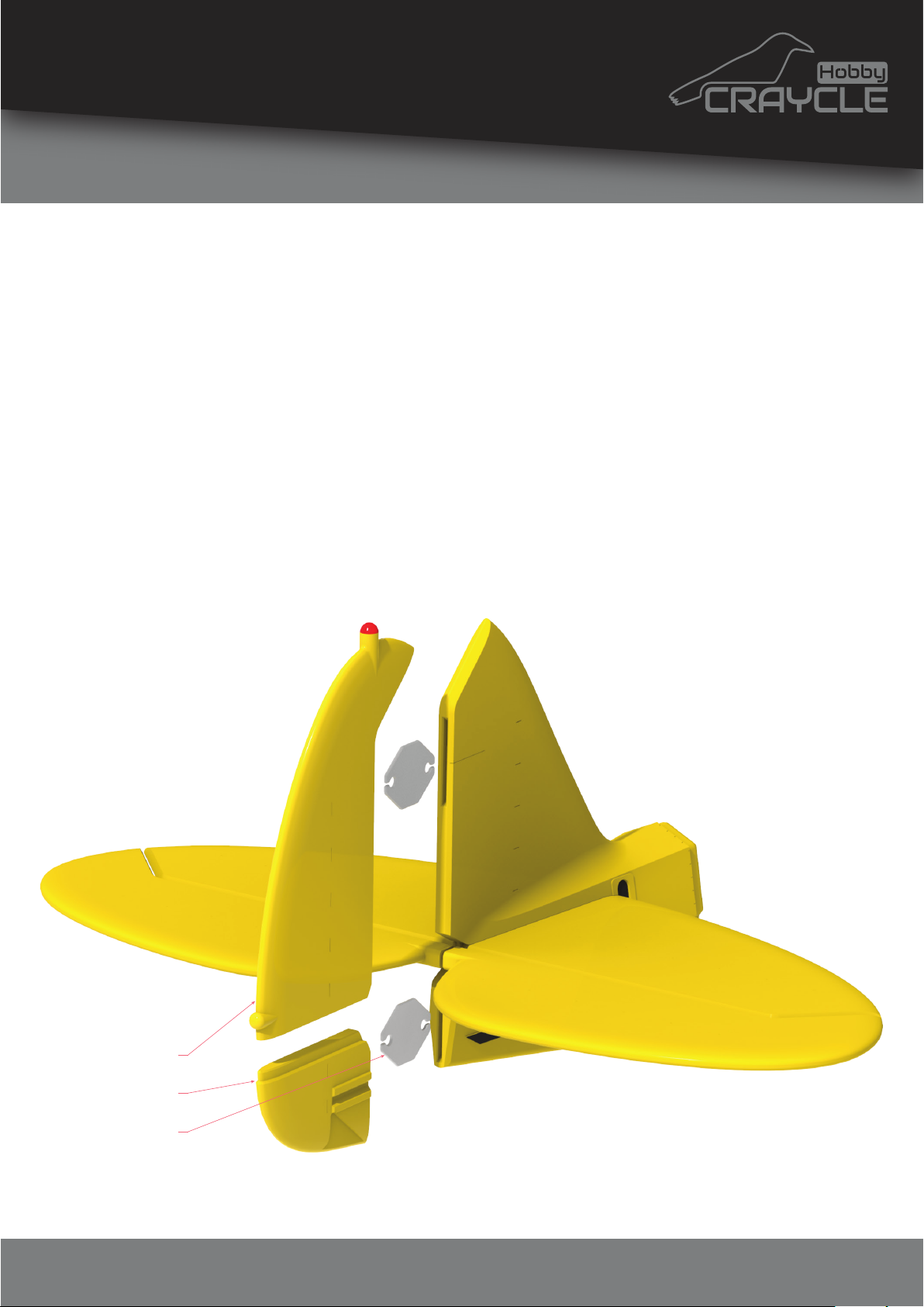
STEP 4
Glue the "rudder1" and “rudder2” parts together by inserting
“cub_pim”.
Glue the rudder you prepared to the tail by inserting hinges
into it’s slots.
Note: The CA accelerator sprayed to stick the elevator may have
contaminated the hinge slots! Take your time, apply the glue
onto the hinges one by one and insert into the slots on the
rudder first.
rudder1
rudder2
hinge
© 2024 Craycle Hobby. Copies allowed for personal use only. Not for commercial use.
Page 8
5
Assembly
www.craycle.com
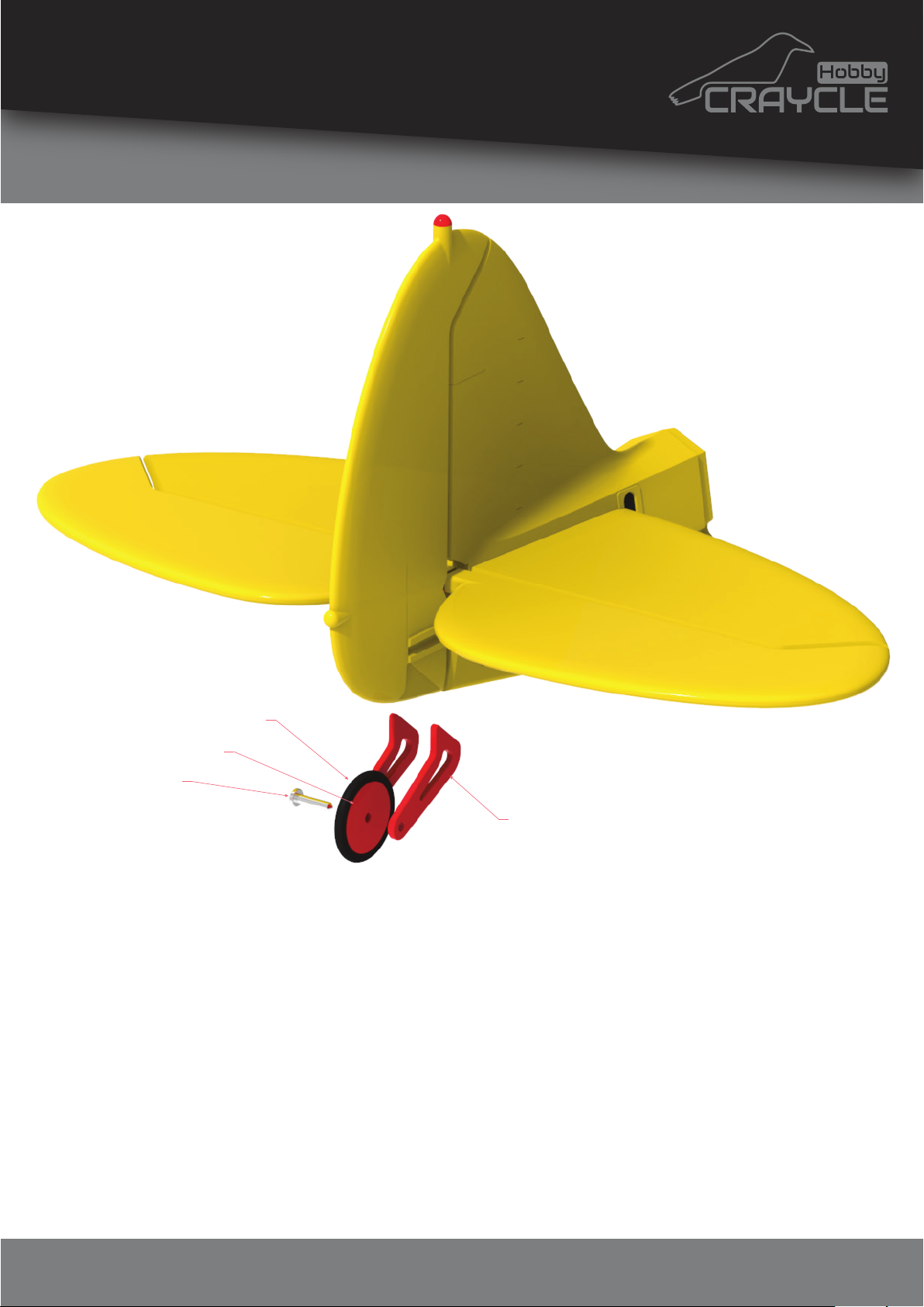
wheel20_ring
wheel20_rim
2 mm steel rod
ruddergear
STEP 5
Clean the little “ruddergear” parts and glue them onto the
slots on the rudder. Assemble the “wheel20_rim” and
“wheel20_ring” parts to get the rear wheel.
Assemble the rear wheel to the rudder gear by using a 2 mm
steel rod or something similar. Glue the steel rod carefully
without applying glue to the wheel. You can apply some liquid
oil to make the wheel turn easily.
That's it! You have a rear landing gear with the steering system.
© 2024 Craycle Hobby. Copies allowed for personal use only. Not for commercial use.
Page 9
6
www.craycle.com
Assembly
STEP 6
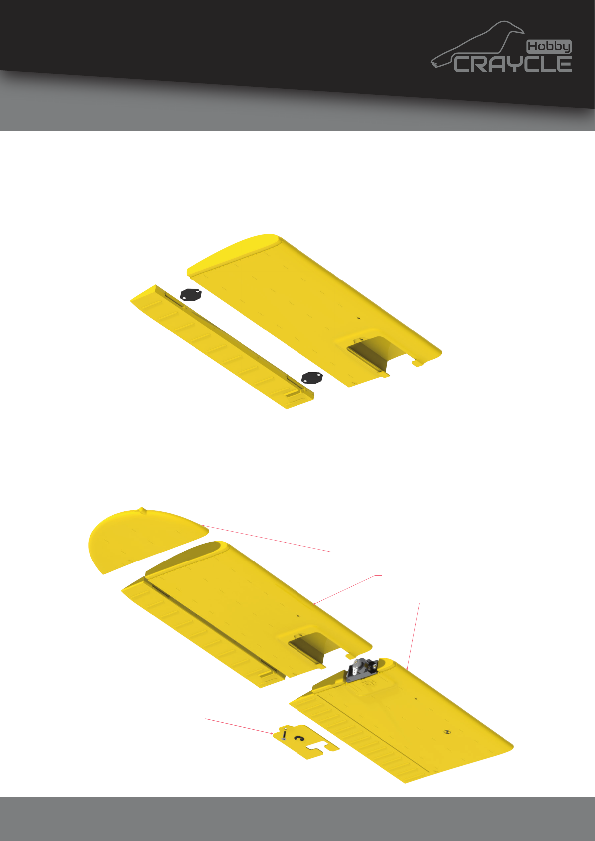
Release the aileron flaps from the “wing2” by breaking it’s tiny
connections and reassemble the aileron using CA hinces.
Take the servo as position as the same in the image below and
screw onto the “wing1” part. Then you can glue the “wing1”“wing2” and “wing3” parts together. Be careful not to apply
glue to the servo and same process goes for the other side.
wing3
wing2
wing1
servohatch
© 2024 Craycle Hobby. Copies allowed for personal use only. Not for commercial use.
Page 10
7
Assembly
www.craycle.com
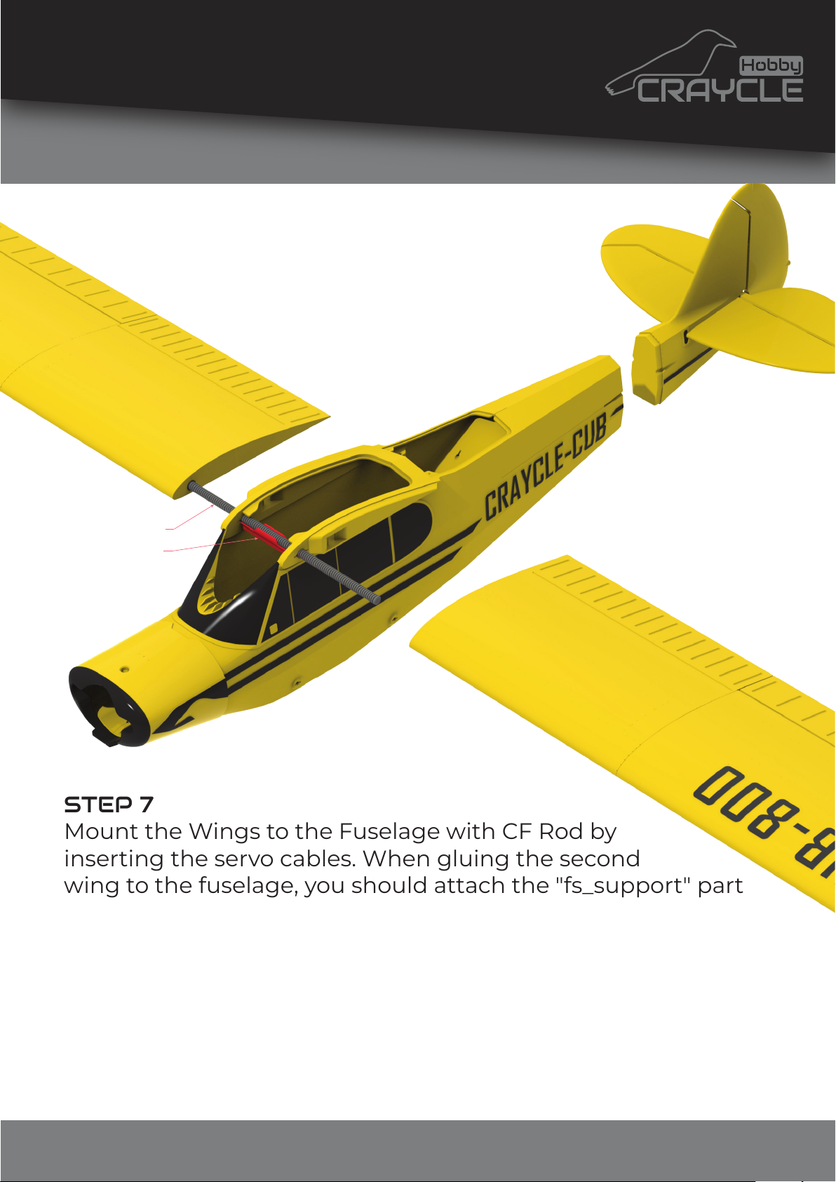
Ø5x170 CF Rod
fs_support
STEP 7
Mount the Wings to the Fuselage with CF Rod by
inserting the servo cables. When gluing the second
wing to the fuselage, you should attach the "fs_support" part
to the CF Rod. In this way, the fuselage width will be preserved.
The "fs_support" part should be glued to the fuselage to
prevent the fuselage from stretching. Apply a minimum
amount of adhesive to the CF Rod to be able to reuse it.
Stick the tail that you prepared to the fuselage by inserting it’s
slot to facilate assembly.
© 2024 Craycle Hobby. Copies allowed for personal use only. Not for commercial use.
Page 11
8
www.craycle.com
Assembly
STEP 8
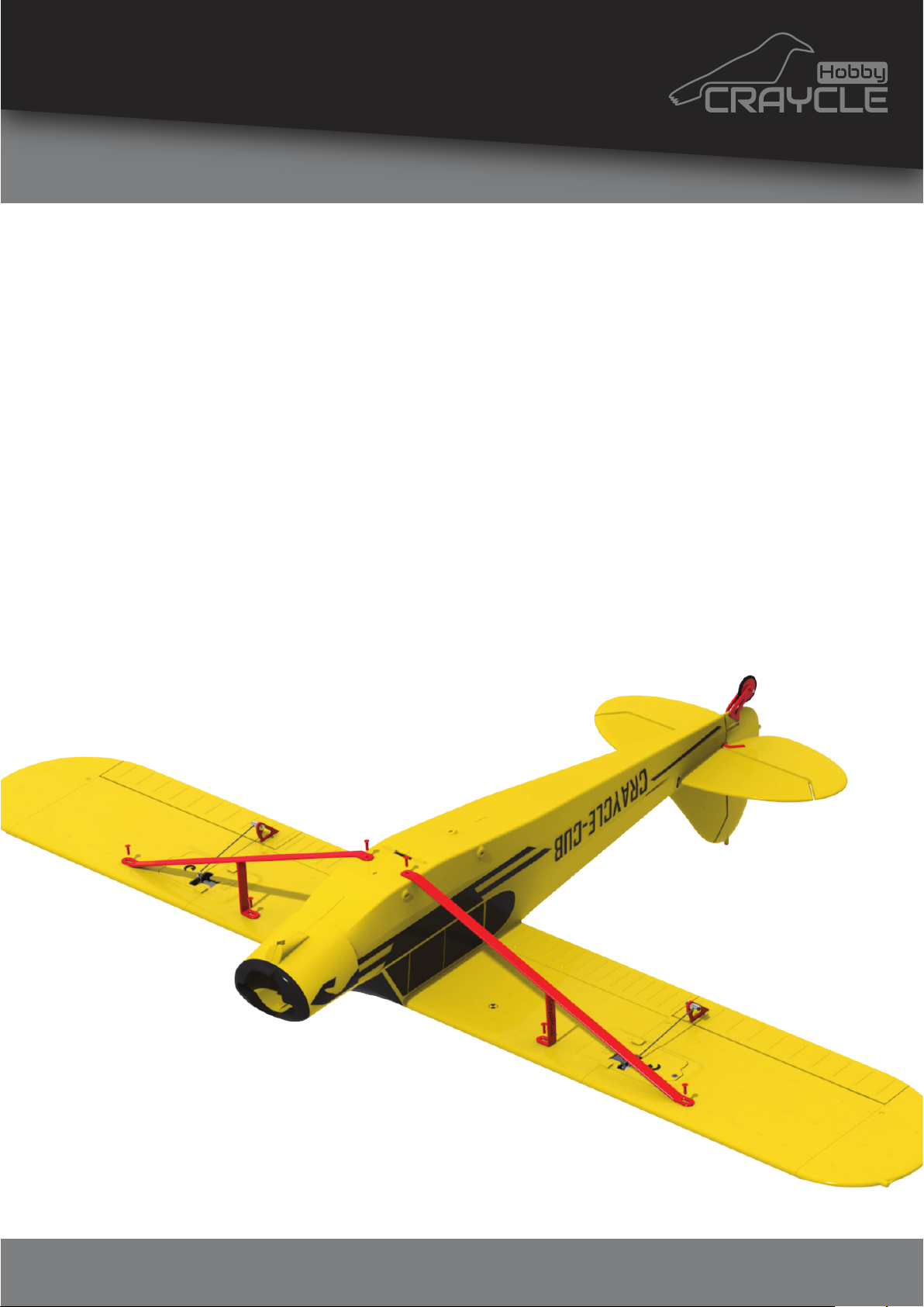
In this step, take your time and do it right!
You need to be sure the wings are holded in a straight line
(Hold the model upside down on the flat table).
Then you can screw the “wingsupport” part by using 2 mm
screws (Servo mounting screws) into the holes on the wings
and fuselage.
When assembly is complete, turn the model over and check
the flatness of the wings.
© 2024 Craycle Hobby. Copies allowed for personal use only. Not for commercial use.
Page 12
9
Assembly
www.craycle.com
STEP 9
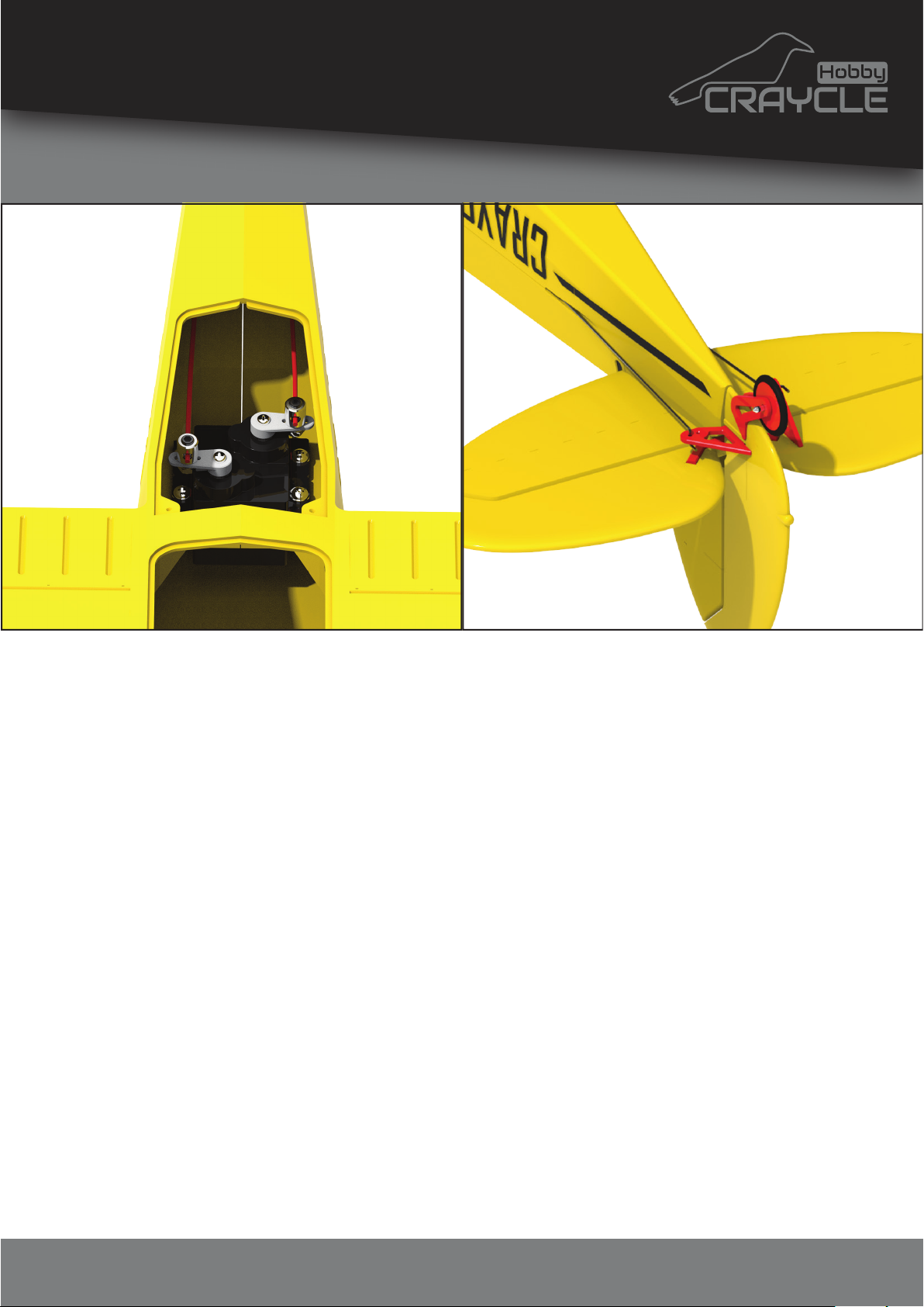
Install your servos to the fuselage and prepare 2 pieces of 1,2
mm pushrods which is approximately 210 mm length.
You can make Z bend for the both side or use rod linkage to
make detachtable and facilate to set the flap positions.
For this model, the best way to mount the push rods is; Z-bend
is mounted on the outside, the push rod connectors are
mounted on the servo arms inside. In this way, connectors are
installed quick, it becomes possible to deassemble the wires,
and the objects that will create drag are reduced on the
outside.
You can use cheap 9 gram servos for this model becouse of it's
not required high sensitive on the control surfaces.
© 2024 Craycle Hobby. Copies allowed for personal use only. Not for commercial use.
Page 13
10
Assembly
www.craycle.com
STEP 10
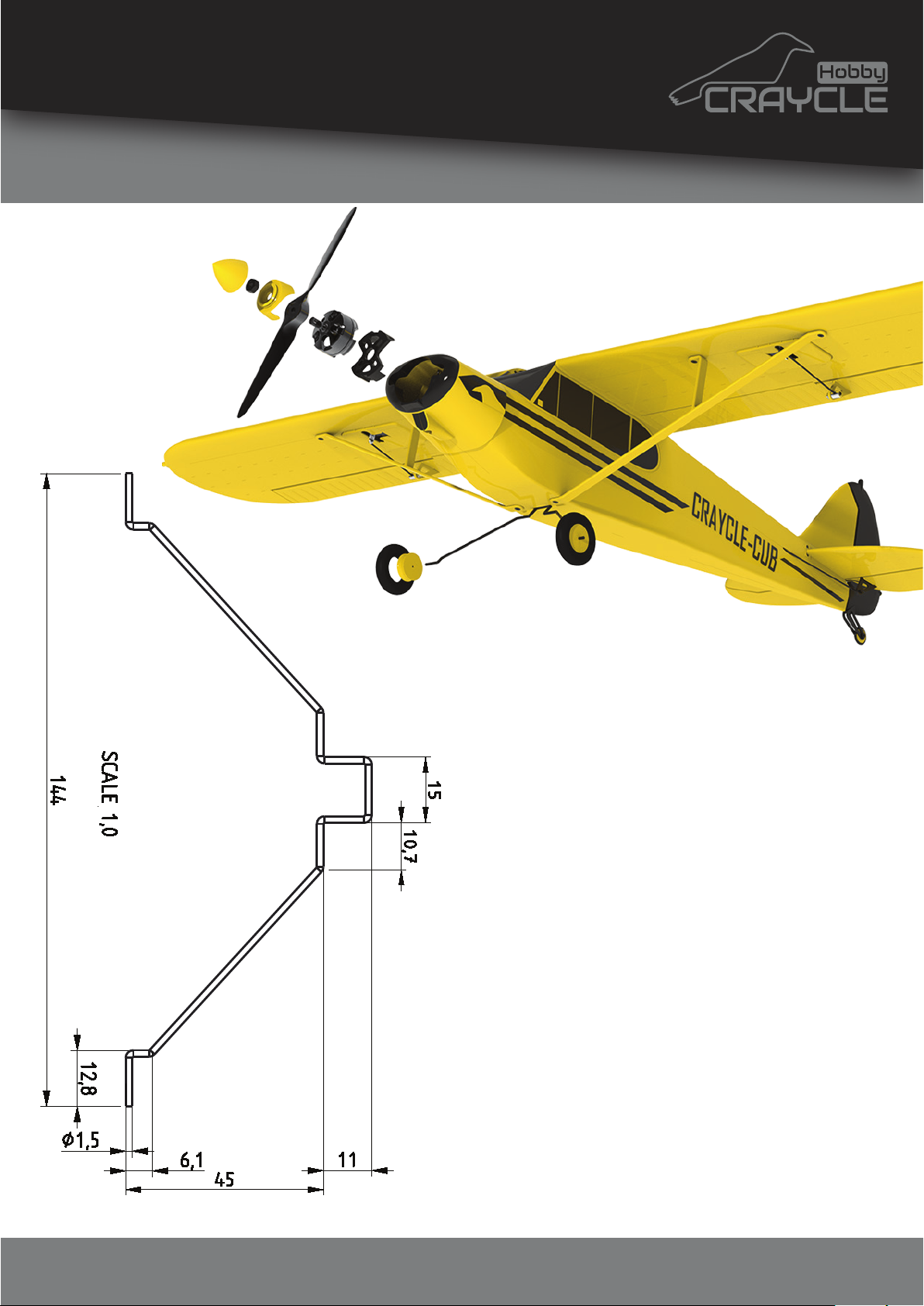
Prepare quick release landing
gear by using 2mm steel wire. You
can use this page by printing as
%100 scale and also you can use
the dimensions as mm.
Assemble the “wheel35_ring” and
“wheel35_rim” parts together and
install them onto the landing gear
that you prepared (You can make
a clear hole in the “wheel35_rim”
by drilling it with 2 mm drill bit.)
Glue the “spinner_adaptor” and
“spinner_base” parts together by
inserting 5 mm rod to make it
centered. Assemble the spinner,
motor and landing gear as shown.
© 2024 Craycle Hobby. Copies allowed for personal use only. Not for commercial use.
Page 14
11
www.craycle.com
Assembly
STEP 11
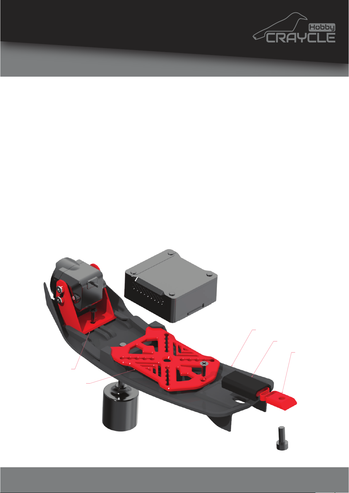
Glue the “lock_body” part into the “hatch1”. Assemble the
“lock_catch” part by using m3x8mm bolt.
New Craycle FPV Cam and VTX mounts allow you to mount
any FPV system in the market. You can adjust the camera
position and fix it with a 2 mm screw. You can mount any FC
with 10x10 to 35x35 mm VTX mounting holes on the bracket or
stick with double-sided tape. You can also use zip ties to fix the
VTX to the mount.
You can use a soldering iron to drill Hatch for FPV Antennas.
hatch1_fpv
fpvcam_mount
lock_body
lock_catch
vtx_mount
© 2024 Craycle Hobby. Copies allowed for personal use only. Not for commercial use.
Page 15
12
Epilogue
www.craycle.com
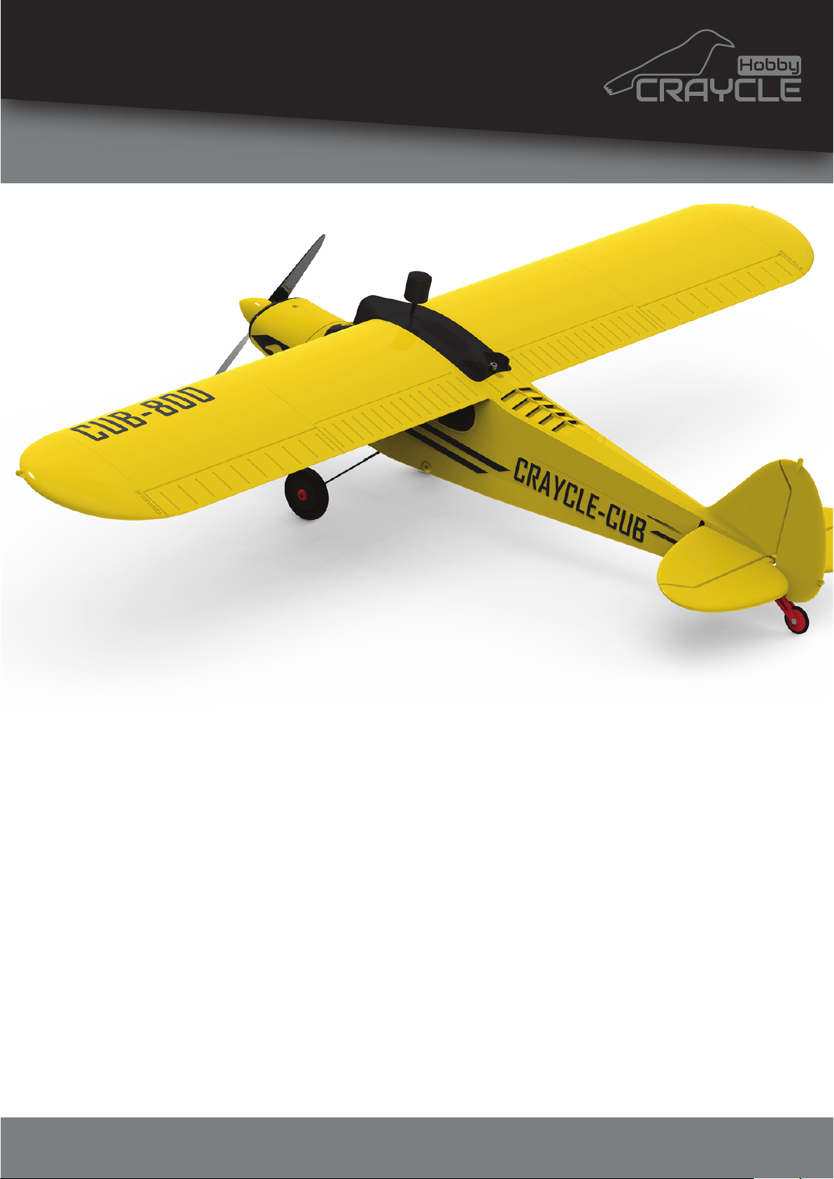
You can also prefer the Hatch1_flat and Hatch2_flat to make to
model real scale if you fly without FPV. Use 2 mm screws to
mount Hatch2 and drill before screwing.
You can add extra weights into the “fs1” to make CG correct.
With Cub V2, CG is way easier to set correctly than before.
Make sure the model is a little bit nose-heavy for the first flight.
You can print this model completely with LW-PLA to make it a
park flyer but it’s not necessary at all. Regular PLA will be
enough thanks to the new design approach.
We recommend 6” propellers for this model but can also use a
7" propeller to make it model fly slower.
© 2024 Craycle Hobby. Copies allowed for personal use only. Not for commercial use.
Page 16
13
Epilogue
www.craycle.com
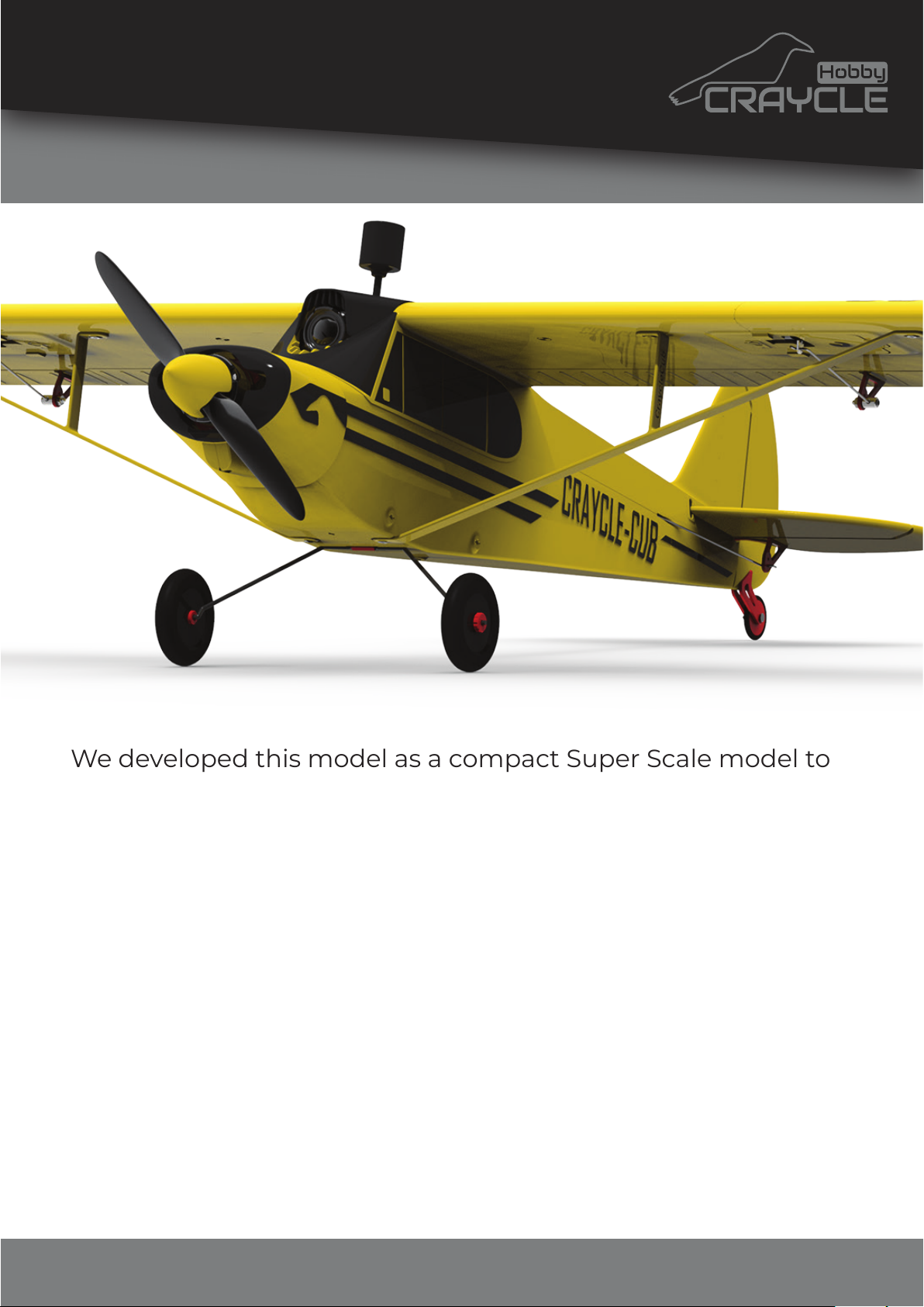
We developed this model as a compact Super Scale model to
experience FPV flight from the real pilot's perspective. With V2,
the model became even lighter and slower. So this model can
also be used as a Trainer.
Enoy with free upgrade with CraycleCub V2! Please check
update notes on craycle.com.
We are always continue to improve the model after published.
Usually this happens becouse of requests. If you need some
feature that is gonna be improve your user experience on this
model, please join the Next Model Survey on craycle.com.
Is there a missing information in this guide? Please let us
know. Thank you for supporting us by building our models!
© 2024 Craycle Hobby. Copies allowed for personal use only. Not for commercial use.
Page 17

1
www.craycle.com
Print Guide
We have prepared printer profile on Cura Slicer for you. If you
have a Marlin XYZ type printer, you can print directly with
provided gcodes as well. If you can’t use the gcodes don't
worry, just follow the instructions...
1) Go to the Cura Profile Article to download Cura V4.13.1 and
import craycle.curaprofile.
Article: https://craycle.com/craycle-cura-profile/
2) Change this settings according to your printer:
- Material Settings.
Nozzle Temperature
Buildplate Temperature
Flow (wall flow is important!)
- Travel Settings.
Retraction distance
Retraction speed
We make internal supports by creating gaps in the model parts.
So, the "Slice Gap Closing" value should be 0 mm or closed.
Turn off all gap-filling features in the slicer.
You should print the biggest wing part of the model to test
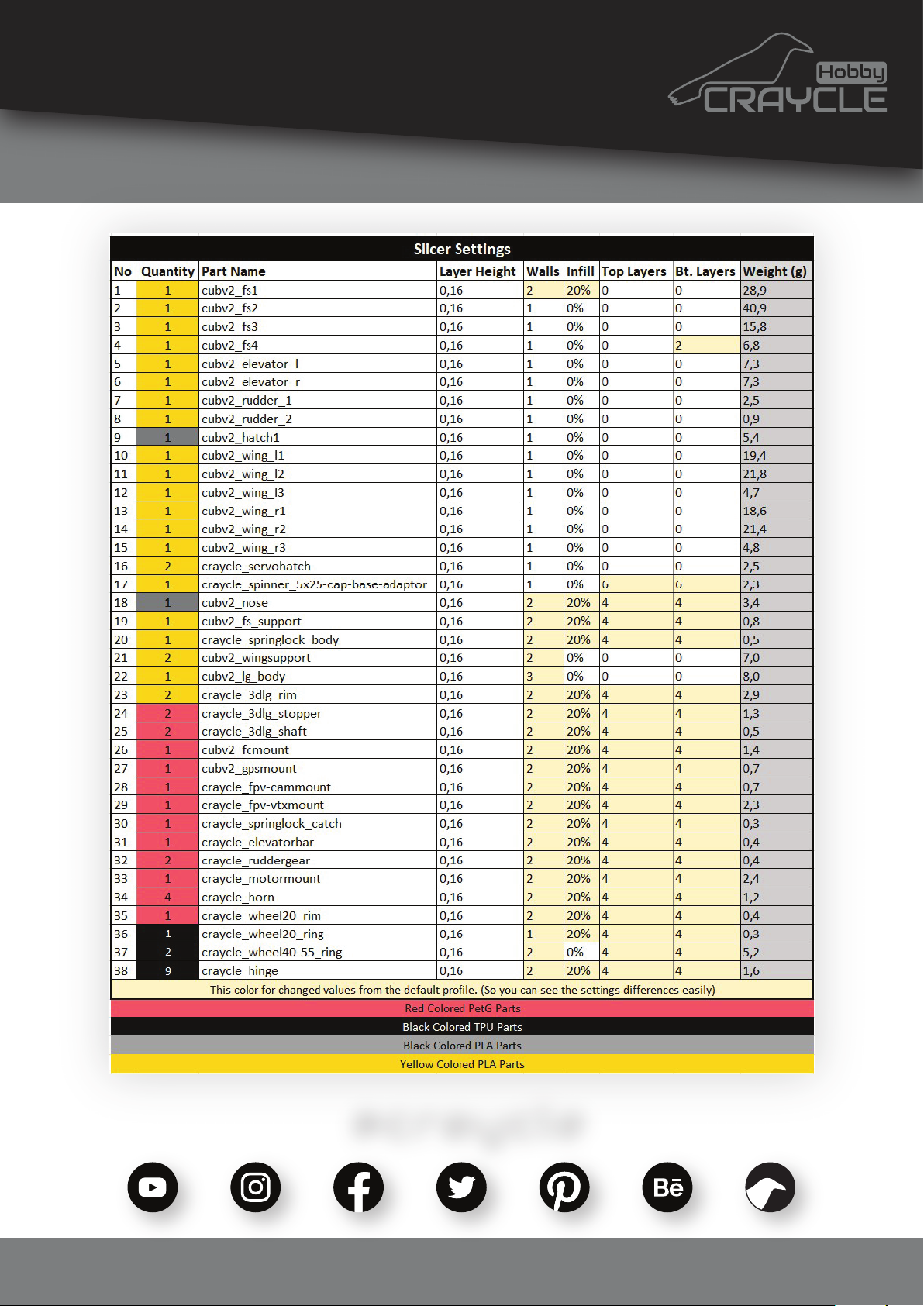
your printer. Make sure the wing weight is equal to the settings
table! Then you are ready for the rest of the model parts.
This process will both verify your extruder flow and verify your
printer settings correctly. If you have mechanical problems on
your printer, you will also see that mesuring the model weight.
© 2024 Craycle Hobby. Copies allowed for personal use only. Not for commercial use.
Page 18
2
Print Guide
www.craycle.com
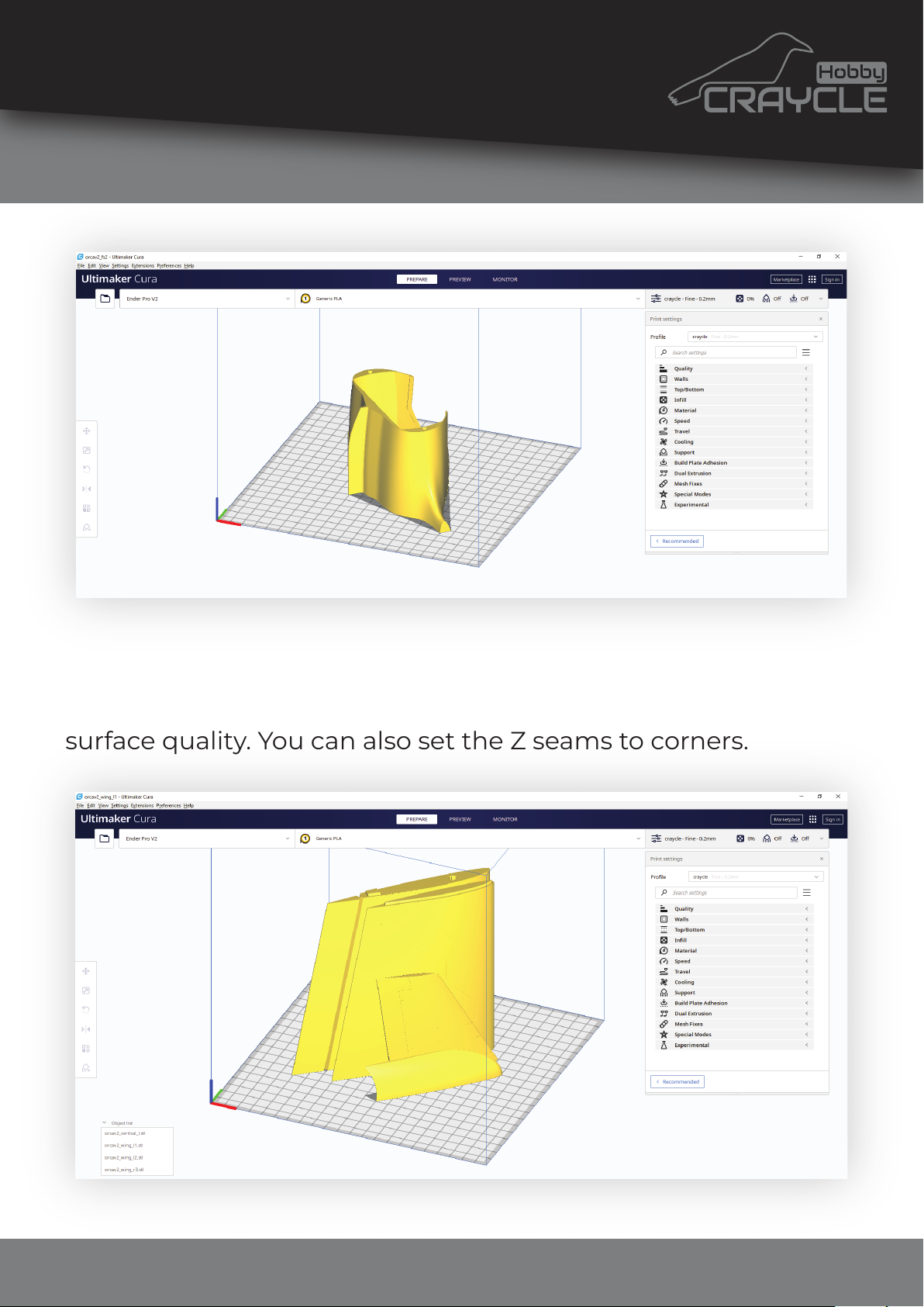
We pre-routed the model parts for you but still make sure the
model parts are oriented at 45 degrees to the bed. This way X
and Y axis works coordinated and you can get maximum
surface quality. You can also set the Z seams to corners.
© 2024 Craycle Hobby. Copies allowed for personal use only. Not for commercial use.
Page 19
3
Print Guide
www.craycle.com
@craycle
© 2024 Craycle Hobby. Copies allowed for personal use only. Not for commercial use.
 Loading...