

CRAY CX1
QUICK START USER’S GUIDE
CX1 QUICK START GUIDE SECTIONS
GETTI NG TO KNOW THE CX1
(RED SECTIO N)
STAGE 1 - UNPACKING
(BLUE SECTIO N)
STAGE 2 - PRE-ASSEMBLY
(YELLOW SECT ION)
STAGE 3 - ASSEMBLY
(GREEN SECTIO N)
UNPACKING
STAGE 4 - POW ERING THE C X1
(GREY SECTI ON)
Installatio n and Service:
To avoid injury from e lectrical sho ck, only
qualified tech nical service p ersonnel can
perform any t ype of service o r installation on
this system .
Enclosure Cover :
In compliance w ith applicable sa fety, emission,
and thermal req uirements, no c overs should
be removed and a ll bays must be fille d with
compute shel ves.
Electrostatic Discharge:
Observe normal Ele ctrostatic Di scharge (ESD )
procedures d uring system int egration to avoid
possible dam age to the server b oard and/or
other compon ents of the syste m.
Shipping Information:
Do not ship any CX1 co mpute shelves wi thin the CX1
system chas sis. Doing so may re sult in damage to
the CX1 system .
CX1 System Power :
The power cord mus t be disconnect ed before
installing or r emoving any shelve s. Dedicate a
20 Amp AC Outlet ex clusively to the C X1.
The high proce ssor count of the C X1 could require
the draw of a full 20 Am p circuit.
Safety Information:
Before removing the C X1 system from its b ox,
to prevent any dam ages to the syste m itself or
injury to the pe rson handling the C X1, all the
safety caut ions must be read .
GETTING TO KNOW THE CX1
Power Inlet 110-250V
50-60Hz 20A
Future
Expansion
REAR PANEL
USB 1 USB 2
(to front of system)
USB
(to DVD-ROM)
ZONE B
ZONE A
ZONE B
ZONE A
PS 1
PS 2
PS 2
PS 1
FRONT PANEL
DVD-ROM
USB PORT 2
ZONE A POWER
ZONE B POWER
USB PORT 1
FRONT-PANEL LCD
GET 1.1
GET 1.2
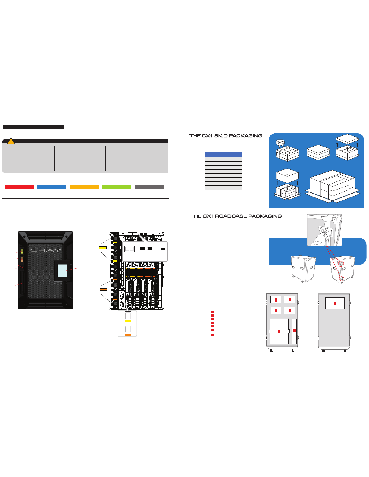
THE CX1 SKID PACKAGING
STEP 1
STEP 2
STEP 3
STEP 4
1
7
8
5
5
6
6
4
2
3
Box Contents
Qty
[1] Documentation Box
1
[2] Chassis Cart Box
1
[3] Rail Box
1
[4] Main Chassis Box
1
[5] Power Supply Box
2
[6] Blade Box
2
[7] Cables
1
[8] Accessories
1
Unlocking the CX1 ROAD CASE
Remove the front p ortion of the case (2 latc hes on the right side)
5
1
2
43
6
FRONT
5
CX1 ROAD CASE
Package Contents
Shelf Slot #1
Shelf Slot #2
Shelf Slot #3
Shelf Slot #4
Main Chassis
Slot Containi ng :
- Rails and/o r Chassis Cart
1
2
3
4
5
6
Accessory Ar ea
Containing :
- Keyboard & Mous e + Batteries
- RJ-45 C ables
- Packing Slip
- (Optional ) Infiniband Cab les
7
BACK
7
THE CX1 ROADCASE PACKAGING

PRE-ASSEMBLY
FOR CX1 RACK MOUNT VERSION ONLY
Rail Kit
MEASURE TH E INSIDE
OF THE MOUNT ING POSTS
FRONT VIEW
1U
2U
3U
4U
5U
6U
7U
RAIL HEIGHT
8U
Cage Nut
TOP OF RAIL
STOPS HERE
BOTTOM OF RAI L
STOPS HERE
TOP OF RAIL
STOPS HERE
BOTTOM OF RAI L
STOPS HERE
APPLY NUTS TO SCRE WS - DO NOT TIGHTEN J UST YET
BACK VIEW
INSERT SCRE WS
FRONT VIEW
OVERLAP FRO NT
BACK
FRONT
EXTEND TH E RAIL TO MEASUR EMENT TAKEN FROM STE P PREASM 1.1
PREASM 2.1
Use Screwdr iver
FRONT VIEW BACK VIEW
PREASM 2.2
PREASM 2.4
2
Installing the Rails
(Rack Mount Vers ion Only)
1) Position and align the r ails inside the rack.
2) Attach both the lef t and right rails to the rack by in serting three (3) s crews in
the front and thre e (3) screws in the back.
3) After the Rail s have been secured in the Ra ck, tighten the four (4 ) screws used
in steps PREA SM 1.4 and PREASM 1.5 of the Rail P reparation Section.
4) Insert s upplied cage nuts in the m ounting posts of the rack . This needs to be
done on both side s, left and right, in th e front only. There are a total of t wo (2)
“cage nuts” inst alled on each side. These “ca ge nuts” are used to secure t he
chassis to the rac k.
PREASM 2.3
TIGHTEN FOUR SCREWS
FROM STEPS PREASM 1.4 AND 1.5
PREASM 1.3
1) Measure the dis tance between the fr ont and
rear mount pos ts inside the rack.
Since the rails are to b e mounted on the inside
(between ) the mount ribs, make sure to t ake
the measureme nt on the inside of the mount
posts and not t he outside.
2) Lay the back po rtion of the rail on its back
with the porti on used to mount on the rack
pointing upward s. Rest the Front porti on of
the rail overlappin g the back portion alignin g
the holes on both p arts.
3) Extend t he rail to the measurement ta ken
from Step 1)
4) Insert t he four (4) supplied s crews into the
holes of the front p ortion of the rail passin g
through the back p ortion.
5) Attach the fo ur (4) supplied nuts t o the
inserted s crews . Do not tighten the nut s.
NOTE: For bes t strength results, al ign so that no
more than two ( 2) screws are installe d in a single
opening loca ted in the back portion of t he rail.
1
Rail Preparation
(Rack Mount Vers ion Only)
PREASM 1.1
PREASM 1.2
PREASM 1.4
PREASM 1.5
Inserting the Compute Blade into
the CX1 Main Chassis
1) Gently remove th e blades from the CX1 packagi ng.
2) Remove each com pute blade from its resp ective anti-sta tic bag.
3) Each blade will h ave a label on it (example sh own in figure ASM1.1 below) which sh ould be used to identif y where to place the
blade into th e main chassis. If you are faci ng the rear of the main chassis , the recommended po sition for the blade desig nated
position A1 is the to p left-most locati on (A1, as indicated on the middle -portion of the backof th e CX1 chassis, seen in fig ure
ASM 1.2 bel ow).
Note: W hen inserted, the bla de connectors will blin d-mate into the front of the c hassis.
4) Continue to in sert the remaining blad es.
WARNING: Depen ding on its configuration, a C X1 blade can weigh up to 18lbs and th erefore must be handled w ith care.
1
ASSEMBLY
Chassis Cart Installation
1) Remove the prote ctive bubble wrappin g from each of the main 3 compone nts of the chassis car t;
all compon ents can be found in slot # 6 of the CX1 ROADCASE.
2) Place the empt y CX1 main chassis onto the c hassis cart seen (i n figure PREASM1.2) bel ow.
3) The cart w ill sit on the chassis car t as shown (in figure PREA SM1.3) below.
1
PREASM1.2
PREASM1.3
ASM1. 2
AS M1.1
Unit:
Master:
*012345678901*
*012345678901*
Model:
SYSTEM: xy Position: A1
FOR CX1 CHASSIS CART VERSION ONLY
Chassis Cart Kit

Connecting the CX1 Cables
With the blades n ow inserted, plug in th e necessary cable s including:
• Power cable (s):
If your CX1 syste m makes use of blades in both Zo ne A (slots A1 through A4)
as well as Zone B (s lots B1 through B4), you w ill need to connect a Power C able
to each power zone inl et.
• USB cable (for DV D-ROM):
In order to conne ct the front-mounted sl ot-load DVD-ROM driv e to the blade of your
choosing, sim ply connect the USB cab le from the USB connecto r labelled “DVD” on the
rear of the chassi s and plug it into the USB por t of the blade of your choosin g.
• USB cable (for Fro nt USB ports):
In order to make use of a d evice connected to the f ront USB port on any blade ,
do the following :
- To make use of the front lef t USB port, connec t the USB device in questi on to this port.
Following this, o n the back of the chassis, c onnect the short US B cable (provided) to t he
port labelle d USB2; connect the ot her end of the USB cable to the b lade of your choosing.
- To use the front right US B port, repeat the abo ve, but use the port lab elled USB1
on the back of the cha ssis.
The back of the C X1 chassis is color-coded.
• Ethernet cabl es:
The Ethernet p ortion of the back of the C X1 chassis is highlighted in PURPLE.
Use the PURPLE Et hernet cables to conne ct each blade to the built-in G igabit
Ethernet swit ch.
Note: With th e blades inserted into t he chassis, the upper E thernet port on each bl ade is
the first por t (eth0 in Linux).
• Infiniban d cables:
The Infiniband p ortion of the back of the C X1 chassis is highlighted in BLUE .
Use the BLUE Infinib and cables to connect e ach blade’s Infiniband -port to the Infini-
band port of you r choosing.
2
1
3
5
7
2
4
1
3
6
8
5
7
2
4
6
8
1
3
7
Note: As seen above, Visualization and Storage nodes each take 2 slots in a CX1 chassis.
5
1
5
3
7
2
4
6
8
2
4
6
8
ASM 2.1
ASM2.2
ETHERNE T
INFINIBAND
POWERING THE SYSTEM
ZONE A POWER
ZONE B POWER
PWR 1.1
Powering the CX1 from the LCD
The first ste p to powering on the CX1 syst em is to turn on the
breaker(s) o n the front of the chassis.
The top breaker on th e front of the chassis (se en in figure PWR 1.1
to the left) pow ers on the front-panel LCD. S hould you have blades
connected in ZO NE B, this breaker will need to be t urned on as well.
Powering the CX1 from the chassis
1
2
Once the LCD is turn ed on and loads up the CX1
application, t he menu seen in figure PW R 2.1 will
appear. At this stag e, the red power button ( circled
in figure PWR 2.1 to the rig ht) should be presse d.
PWR 2.1
Powering the CX1 from the LCD
3
The menu seen in f igure PWR 3.1 should be
displayed; a t this stage, the green “Im mediate
POWER ON” but ton should be pressed .
PWR 3.1
1-866 - 277- 9C X1
CX1SUPPORT@CRAY.COM
SUPPORT
*44038*
CX1_44038_QRG_1_0
November 2008
 Loading...