

Cray CS-Storm 500GT 3U Hardware Manual
CS-Storm™ 500GT 3U Server Hardware Guide
(Rev C)
H-6150

Contents
Contents
About the CS-Storm 500GT 3U Server Hardware Guide..........................................................................................3
System Description....................................................................................................................................................8
Server Components.................................................................................................................................................11
Controls and Indicators..................................................................................................................................14
Drive Support and Configuration...................................................................................................................17
System Interconnect Diagram.................................................................................................................................19
PCIe Architecture.....................................................................................................................................................20
PCIe Connections and Cabling................................................................................................................................21
Power Distribution....................................................................................................................................................23
Power Supplies..............................................................................................................................................24
Hydra Fan Control Utility..........................................................................................................................................25
Management Daughter Card (MDC)........................................................................................................................35
MDC Control Panel........................................................................................................................................35
MDC DIP Switch Configuration.....................................................................................................................36
PCIe Bifurcation of the 4 PCIe Switch Board...........................................................................................................39
Environmental Specifications...................................................................................................................................40
S2600BP Motherboard Description.........................................................................................................................41
S2600BP Component Locations...................................................................................................................43
S2600BP Processor Socket Assembly..........................................................................................................48
S2600BP Architecture...................................................................................................................................50
S2600BP Processor Population Rules..........................................................................................................51
S2600BP Memory Support and Population Rules.........................................................................................52
S2600BP Configuration and Recovery Jumpers...........................................................................................53
S2600BP BIOS Features...............................................................................................................................56
H-6150 (Rev C) 2
About the CS-Storm 500GT 3U Server Hardware Guide
About the CS-Storm 500GT 3U Server Hardware Guide
The Cray® CS-Storm 500GT™ 3U Server Hardware Guide H-6150 describes the 3U server (Model 7201)
components and features. This guide does not include information about peripheral switches or network fabric
components. Refer to the manufacturer's documentation for peripheral equipment.
Document Versions
Table 1. Record of Revision
Publication Title Date Updates
CS-Storm™ 500GT 3U Server Hardware Guide H-6150 Rev C Feb 2018 Volta 100 GPU.
CS-Storm™ 500GT Hardware Guide H-6150 Rev B Oct 2017 Technical updates.
CS-Storm™ 500GT Hardware Guide H-6150 Rev A Sept 2017 Original publication.
Scope and Audience
This document provides information about the CS-Storm 500GT 3U server. Installation and service information is
provided for users who have experience maintaining high performance computing (HPC) equipment. Installation
and maintenance tasks should be performed by experienced technicians in accordance with the service
agreement.
Related Publications
● CS-Storm 500GT Hardware Replacement Procedures H-6159
Acronyms and Terms
The following table lists the acronyms and their definitions used in this guide.
Acronym Definition
Accelerator Specialized hardware that performs some functions more efficiently than is possible
with software running on a more general-purpose CPU. GPU-accelerated computing is
the use of a GPU together with a CPU to accelerate scientific, analytics, engineering,
consumer, and enterprise applications. In use, GPU accelerator is often shortened to
GPU.
ASHRAE American Society of Heating Refrigeration and Air Conditioning Engineers.
BIOS Basic Input/Output System. Non-volatile firmware used to perform hardware
initialization during the booting process, and to provide runtime services for the
operating system.
H-6150 (Rev C) 3

About the CS-Storm 500GT 3U Server Hardware Guide
Acronym Definition
Bridge board Bridge board. A PCI board/card that provides front panel control signals from the
motherboard to the power backplane and SATA signals from the motherboard to the
disk backplane.
FPGA Field Programmable Gate Array. An integrated circuit designed to be configured by a
customer after it is manufactured.
GPU Graphics Processing Unit (GPU). A processor chip that performs rapid mathematical
calculations, primarily for the purpose of rendering images. GPUs perform parallel
operations on multiple sets of data.
KVM Keyboard Video Mouse (KVM). A rackmounted drawer unit with display screen,
keyboard, and mouse or touch pad used to control multiple computers in a data
centers.
I²C Inter-Integrated Circuit. A multi-master, multi-slave, packet switched, single-ended,
serial computer bus. It is typically used for attaching lower-speed peripheral ICs to
processors and microcontrollers in short-distance, intra-board communication. I²C is
often spelled I2C and pronounced I-two-C.
IFB Interface board. A printed circuit board (PCB) assembly used for the transmission of
signals between different components/systems within the server.
MDC Management daughter card. A printed circuit board (PCB) assembly with IO interface
used to configure, monitor, and manage server subsystems and components.
NVMe Non-Volatile Memory Express (NVMe). A logical device interface specification for
accessing non-volatile storage media attached through a PCI Express (PCIe) bus.
NVMe is commonly flash memory that comes in the form of solid-state drives (SSDs).
PCIe 3.0 Peripheral Component Interconnect Express, 3rd generation I/O.
PCIe switch board A PCIe expansion backplane with 10 PCIe x16 Gen3 slots that expand the
motherboard PCIe lanes and computing resources.
PLX PLX Technology, Inc. is the manufacturer of the PEX8796 PCIe 3.0 multiple-host
switching integrated circuit (IC) chips used on the PCIe switch board.
RU Rack unit. Abbreviated RU or U, is a height measurement defined as 44.5 mm (1.75
in). Most frequently refers to the overall height of 19-inch and 23-inch rack frames, as
well as the height of servers/equipment that mounts in these frames.
SATA Serial AT Attachment (SATA). A computer bus interface that connects host bus
adapters to mass storage devices such as hard disk drives and solid-state drives.
SMBus System Management Bus. A single-ended, simple, two-wire bus used for lightweight
communication. It is typically used in computer motherboards for on/off communication
with the power source.
SSD Solid-state storage device (SSD). SSDs use integrated circuit assemblies as memory
to store data persistently so the data can continue to be accessed. SSDs have no
moving mechanical components as do traditional electromechanical magnetic disks
such as hard disk drives (HDDs).
H-6150 (Rev C) 4
About the CS-Storm 500GT 3U Server Hardware Guide
Acronym Definition
U.2 U.2 formerly known as SFF-8639, is a computer interface for connecting SSDs to a
computer. It uses up to four PCI Express lanes.
UPI Intel® UltraPath® Interconnect. UPI is a point-to-point processor interconnect capable
of up to 10.4 GT/s. With the Intel Xeon Scalable processor family (formerly codenamed Skylake-SP), UPI replaces the Intel QuickPath Interconnect (QPI).
Product EMC Compliance
● FCC Part 15 (USA)
● EN55022 (Europe)
● ICES-003 Emissions (Canada)
● VCCI Emissions (Japan)
● KC Certification (Korea)
Product Regulatory Compliance Markings
The CS-Storm 500GT model 7201 chassis and system components are marked with the following regulatory and
certification markings.
Regulatory
Compliance
FCC Marking
(Class A)
Country Marking
USA INFORMATION TO THE USER
This equipment has been tested and found to comply with the limits for a
Class A digital device, pursuant to part 15 of the FCC Rules. These limits
are designed to provide reasonable protection against harmful
interference when the equipment is operated in a commercial
environment. This equipment generates, uses, and can radiate radio
frequency energy and, if not installed and used in accordance with the
instruction manual, may cause harmful interference to radio
communications.
Operation of this equipment in a residential area is likely to cause harmful
interference in which case the user will be required to correct the
interference at his own expense.
WARNING
Changes or modifications not expressly approved by the manufacturer
could void the user’s authority to operate the equipment.
NRTL (National
Recognized Test
Laboratory)
USA/Canada
H-6150 (Rev C) 5
About the CS-Storm 500GT 3U Server Hardware Guide
Regulatory
Compliance
CE Mark Europe
EMC Marking
(Class A)
VCCI Marking
(Class A)
Country Marking
Canada This Class [A] digital apparatus complies with Canadian ICES-003.
Japan この裝置は, 情報處理裝置等電波障害自主規制協議會 (VCCI) の基準に基
WARNING
This is a class A product. In a domestic environment this product may
cause radio interference in which case the user may be required to take
adequate measures.
Cet appareil numerique de la classe [A] est conforme a la norme
NMB-003 du Canada.
づくクラス A 情報技術裝置です. この裝置を家庭環境で使用すると電波妨
害を引き起こすことがあります.
この場合には使用者が適切な對策を講ずるよう要求されることがありま
す.
C-Tick Marking
(Class A)
Replaceable
Lithium battery
Warning
Information
Low Altitude Use China Only use at altitude not exceeding 2000m.
AC Symbol All IEC 60417-5032
Australia
UL Safety CAUTION
RISK OF EXPLOSION IF BATTERY IS REPLACED BY AN INCORRECT
TYPE.
DISPOSE OF USED BATTERIES ACCORDING TO THE
INSTRUCTIONS
Alternating current
H-6150 (Rev C) 6
About the CS-Storm 500GT 3U Server Hardware Guide
Regulatory
Country Marking
Compliance
Stand-by Symbol All IEC 60417-5009
Stand-by
Trademarks
The following are trademarks of Cray Inc. and are registered in the United States and other countries: CRAY and design, SONEXION, Urika-GX, and
YARCDATA. The following are trademarks of Cray Inc.: APPRENTICE2, CHAPEL, CLUSTER CONNECT, ClusterStor, CRAYDOC, CRAYPAT, CRAYPORT,
DATAWARP, ECOPHLEX, LIBSCI, NODEKARE. The following system family marks, and associated model number marks, are trademarks of Cray Inc.: CS, CX,
XC, XE, XK, XMT, and XT. The registered trademark LINUX is used pursuant to a sublicense from LMI, the exclusive licensee of Linus Torvalds, owner of the
mark on a worldwide basis. Other trademarks used in this document are the property of their respective owners.
H-6150 (Rev C) 7
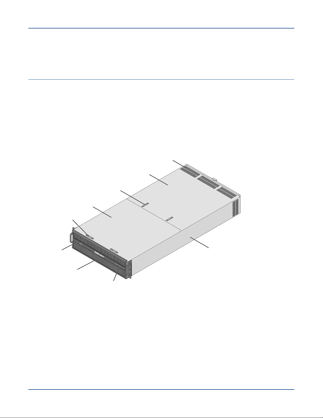
Switches
and indicators
GPU/accellerator card
status LEDs
Front cover
Rear cover
Model 7201
19in 3U chassis
Model 7201A
19in 4U chassis
Cover latches
Front grill
(air intake)
Air vents
(exhaust)
Cover latches
System Description
System Description
The CS-Storm™ 500GT system is a dense 3U or 4U 19-inch wide rackmount server that is optimized to support
today’s highest power GPU or FPGA accelerator cards.
Each 500GT server contains two Intel® Xeon® Scalable processors, up to 1536GB of memory, eight 2.5-in drive
bays, and up to 16 DIMMs. However, for optimal memory performance, 12 DIMMs are recommended to achieve
maximum performance.
Each CS-Storm 500GT server supports up to 10 PCIe GPU or FPGA accelerator cards.
Figure 1. CS-Storm 500GT Server
Server Configuration Options:
● Balanced PCIe Configuration
○ GPU host-to-peer optimized server.
○ Balanced PCIe CPU-to-GPU bandwidth. The balanced PCIe architecture offers balanced performance for
● Custom Accelerator Card Configuration
○ A 4U chassis balanced PCIe server implements the same system PCIe architecture and hardware
H-6150 (Rev C) 8
codes that have high data parallelism and use both the CPUs and GPUs in workload processing.
components but supports extended height custom-sized FPGA accelerator cards.
Table 2. CS-Storm 500GT Server Specifications
Feature Description
Rack options 19in rack, 42RU and 48RU options
System Description
Chassis
Accelerators Up to 10 PCIe accelerators (up to 400W continuous each):
Custom 4U Chassis
Motherboard Intel® S2600BP
● 19-inch wide, 3U or 4U rackmounted chassis
● Up to 15 server chassis in a 48RU rack
● Chassis weight:
○ Up to 76 lb (34kg) without PCIe cards
○ Up to 135 lb (62kg) fully loaded
● 3U Dimensions: (HxWxD) 5.1 x 17.7 x 36.4in (130 x 449 x 925mm)
● 4U Dimensions: (HxWxD) 6.8 x 17.7 x 36.4in (173 x 449 x 925mm)
● NVIDIA® Tesla® P40 or P100
● NVIDIA® Tesla® V100
● Custom extended height full-size FPGA accelerators (4U chassis only)
● Up to eight 425W custom cards
● N+1 power supply redundancy
● Not ASHRAE compliant
● Balanced PCIe configuration
Processors Two Intel Xeon Scalable family processors (up to 165W TDP)
Memory Capacity Up to 12 of 16 available DIMM slots
Up to 1536GB DDR4 (12 x 128GB DIMMs)
For optimal memory performance, 12 DIMMs (1 DIMM per channel, 6 DIMMs per
CPU) are highly recommended.
Storage 2.5in drive bays
NVMe U.2 drive configuration depends on PCIe topology.
Spinning disks are not supported (all SATA disks must be SSDs).
● Up to 8 SATA SSDs in external drive bays (hot swap)
● 4 NVMe SSDs (external bays 4-7)
● 1 or 2 fixed internal SATA SSDs
Some configurations require an additional add-in storage controller
Total number and type of drives vary with configuration and PCIe topology.
Expansion slots
● 2 PCIe 3.0 x16 slots
H-6150 (Rev C) 9
Feature Description
● 2 additional PCIe 3.0 x16 slots can be added with 8 GPUs
System Description
Network adapter cards
Cooling Air cooled (front to rear air flow)
Power Supplies Support for both N+1 and N+N power configurations. Up to four 2200W AC power
● Omni-Path (100Gb/s)
● InfiniBand™ EDR (100Gb/s) or HDR (200Gb/s)
● Ethernet (100Gb/s)
● Seven fans
○ Three 120mm fans (front)
○ Four 80mm fans (middle)
○ Active/manual fan speed control through MDC or hydrad daemon
● Built-in air duct
● Passive processor heatsinks
● Passive GPU/FPGA heatsinks
● Two in-line fans in each power supply unit
supplies, 200-277VAC (gold level efficiency)
● 2+2 redundancy with 10 (300W) accelerators
● 3+1 redundancy with 10 (400W) accelerators (3+1 PSUs required)
Server supports multiple PCIe topologies and configuration options
Node management
IO Ports
● Integrated Baseboard Management Controller (BMC) (IPMI 2.0)
● Management daughter card (MDC)
● MDC supports hydrad daemon to manage fans, GPUs, and PSUs
● Intel remote management module 4 (RMM4)
● RMM4 supports remote KVM and Intel Dedicated Server Management NIC
● On-board RJ45 management port
● Support for Intel System Management Software
● 2 RJ45 10GBase-T LAN ports
● 1 RJ45 dedicated management LAN port
● 2 USB 3.0 ports
● Optional: VGA or serial port
H-6150 (Rev C) 10
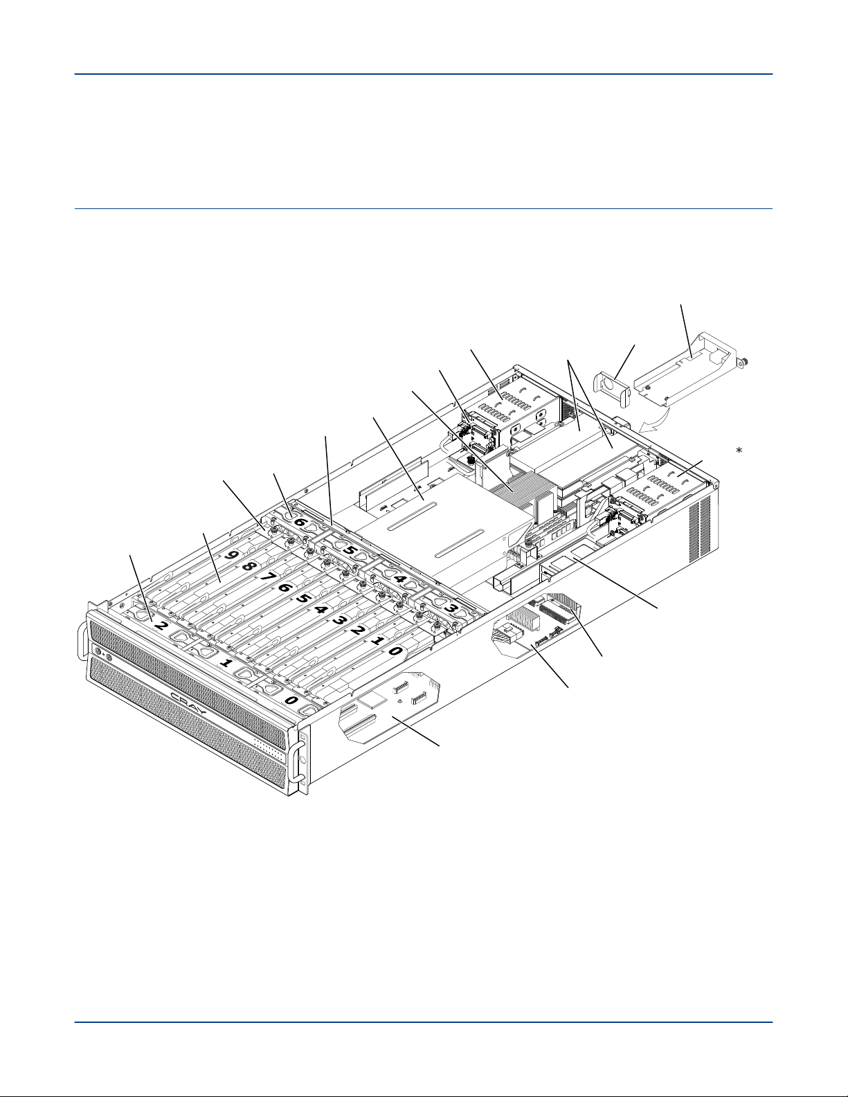
Server Components
PCIe switch board
(under GPUs)
Power backplane
Front fans
120mm (3x)
Middle fans
80mm (4x)
Air duct
Fan cage
GPUs
(slots 0-9)
GPU
carriers
Drive cage 3
internal disk
drives (up to 2)
Heatsink (CPU 1)
Drive cage 2
SATA/NVMe
drive slots (4-7)
Drive cage 1
SATA drive slots
(0-3)
PCIe add-on/
network cards
(up to 4)
Power supply (up to 4)
MDC
Drive cage backplane
PSU
blank
The number of drives and PCIe cards can vary
depending on server PCIe and GPU configuration.
Note:
The major components in the CS-Storm 500GT server are shown in the following figure.
Figure 2. CS-Storm 500GT 3U Chassis Components
Server Components
Fans and fan cage
There are 7 pluggable fans, each with a 4-pin connector on the bottom that plugs into a fan
interface board (front and middle). The fan distribution boards provide an interface between
the fans and the power backplane. The middle fan cage can be removed to provide access
to other chassis components. Air flow runs from front to back.
PCIe switch board
The balanced four PCIe switch board (4 PLX) supports 10 PCIe slots for GPU or FPGA
cards with the option of using slots 4 and 5 for network add-in cards. See PCIe Architecture
H-6150 (Rev C) 11

on page 20. The switch board provides an interface between the motherboard and GPUs
through the PLX device. The switch board also provides a direct power connection to each
GPU slot. GPU status signals are routed to the front panel through the PCIe switches and
over the SMBus.
Power backplane
All power supplies (PSUs) plug into the power backplane. The power backplane distributes
power along with monitoring features to all printed circuit assemblies (PCAs) in the chassis
including the motherboard, front panel controls and indicators, fans, and accelerators. The
power backplane provides a control signal interface between the motherboard and front
control panel. See Power Distribution on page 23.
Drive Cages and Disk Backplane
The drive cages support multiple local storage configuration options. See Drive Support and
Configuration on page 17. Depending on the configuration, one or more of the drive cages
may not be included in the chassis. If a rear-accessible drive cage is not included, a cover is
used to fill the chassis opening.
The rear-accessible drive cages have a disk backplane that extends the motherboard SATA
ports to the drives. The backplanes provide power for the drives and include separate cable
connectors for SATA and NVMe drives. The disk backplane provides PCIe 3.0 x4 for each
drive slot. Drive cage 1 can support NVMe drives with additional PCIe cables, if PCIe lanes
are available.
The internal 2.5in drive cage does not have a backplane. Direct cable connections for power
and SATA signals are used.
Management Daughter Card (MDC)
The MDC is used to configure, monitor, and manage server subsystems and components.
Primary maintenance functions include fan and thermal monitoring and power consumption
monitoring. See Management Daughter Card (MDC) on page 35.
Air duct
The air duct provides proper air flow for the motherboard, DIMMs, and CPU heatsinks. The
air duct is mounted behind the middle fan assembly. Always operate the CS-Storm 500GT
with the air duct in place. The air duct is required for proper airflow within the server chassis.
Accelerator Carriers
Accelerator cards are mounted/screwed to a carrier frame. The accelerator card and carrier
assembly is lowered down into the chassis and seated to the PCIe switch board. Guides on
each end of the carrier fit into slots in the front and middle fan trays. Ejector handles are
used to seat/unseat the assembly. A locking thumbscrew secures the assembly in place.
Server Components
H-6150 (Rev C) 12
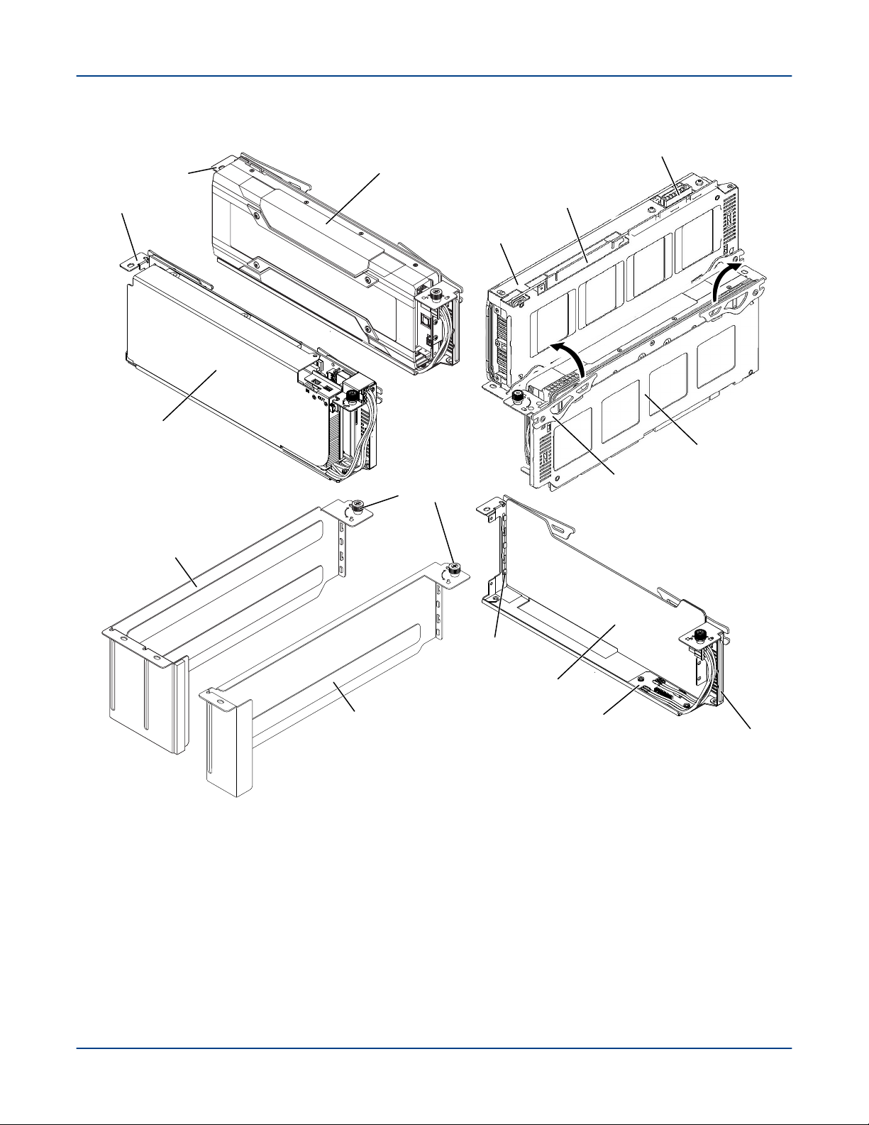
Figure 3. GPU Carriers, Multiple Views, CS-Storm 500GT
Insulator
Power IFB
(connects to PCIe
switch board)
Locking
thumbscrew
Accelerator card
carrier bracket
Ejector
handles
NVIDIA card
Carrier guide
Carrier guide
Blank two-slot
GPU carrier
GPU assembly
(bottom view)
GPU card
PCIe connector
Power connector
FPGA card
FPGA carrier
NVIDIA carrier
Blank one-slot
GPU carrier
Server Components
GPU Installation Order. The figure shows the order for installing GPUs if the chassis is not fully populated. This
installation sequence must be followed to maintain a proper thermal environment. For example, for a 4 GPU
configuration, slots 0, 9, 3, 6, are populated. Slots 2, 7, 1, 8, 4, and 5 would be empty.
If all GPU slots are not fully populated, empty two-slot carriers are installed in the empty slots to maintain proper
cooling.
H-6150 (Rev C) 13
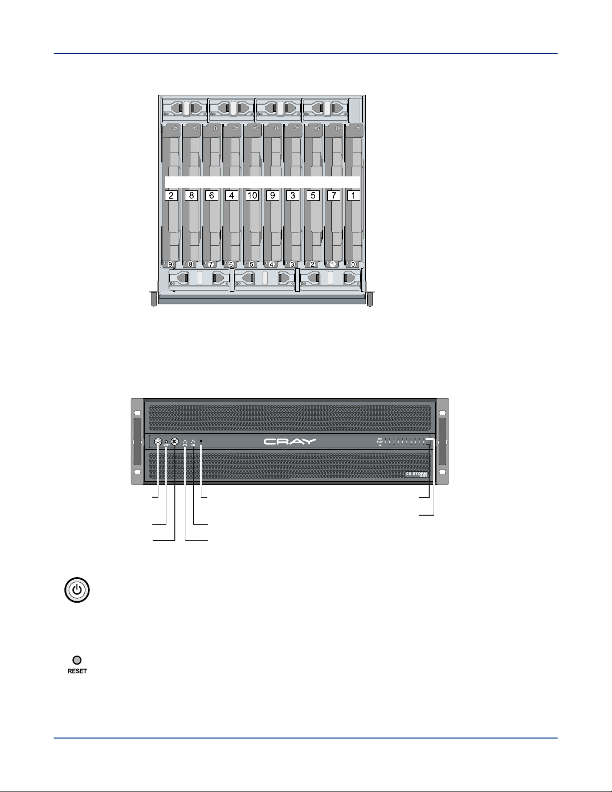
Figure 4. CS-Storm 500GT GPU Installation Order
Slot number Slot number
GPU/PCIe installation order
Front panel
Power button
with LED
Reset button
System ID button
with LED
System health LED
Chassis health LED
GPU status LEDs
PCIe link status LEDs
Synchronize switch
(CRAY logo to CSS indicator)
Server Components
Controls and Indicators
Figure 5. Front Controls - CS-Storm 500GT
Power button [blue]. The power button LED lights blue to indicate system power is on.
The power button is used to apply power to server components. Pressing the power button
initiates a request to the Baseboard Management Controller (BMC) integrated into the
motherboard, which forwards the request to the ACPI power states in the motherboard chip
set. The power button is monitored by the BMC and does not directly control power on the
power supplies.
Reset button. Press the Reset button to shut down, clear memory, and reset devices to
their initialized state.
H-6150 (Rev C) 14
Off
Blinking
Normal operation
PCI, PLX, GPU, PSU, fan failures, SMBus errorsSolid On
Fan, PSU, or SSD failure
Off
Solid On
Normal operation
Non-fatal errorBlinking
Fatal error
On (blue)
On (amber)
Server is powered on or server is powered off but power cable
is connected to power. Unplug the server to remove all power.
Optional. Can be synchronized to have the same indications
as the Chassis Health LED.
Server Components
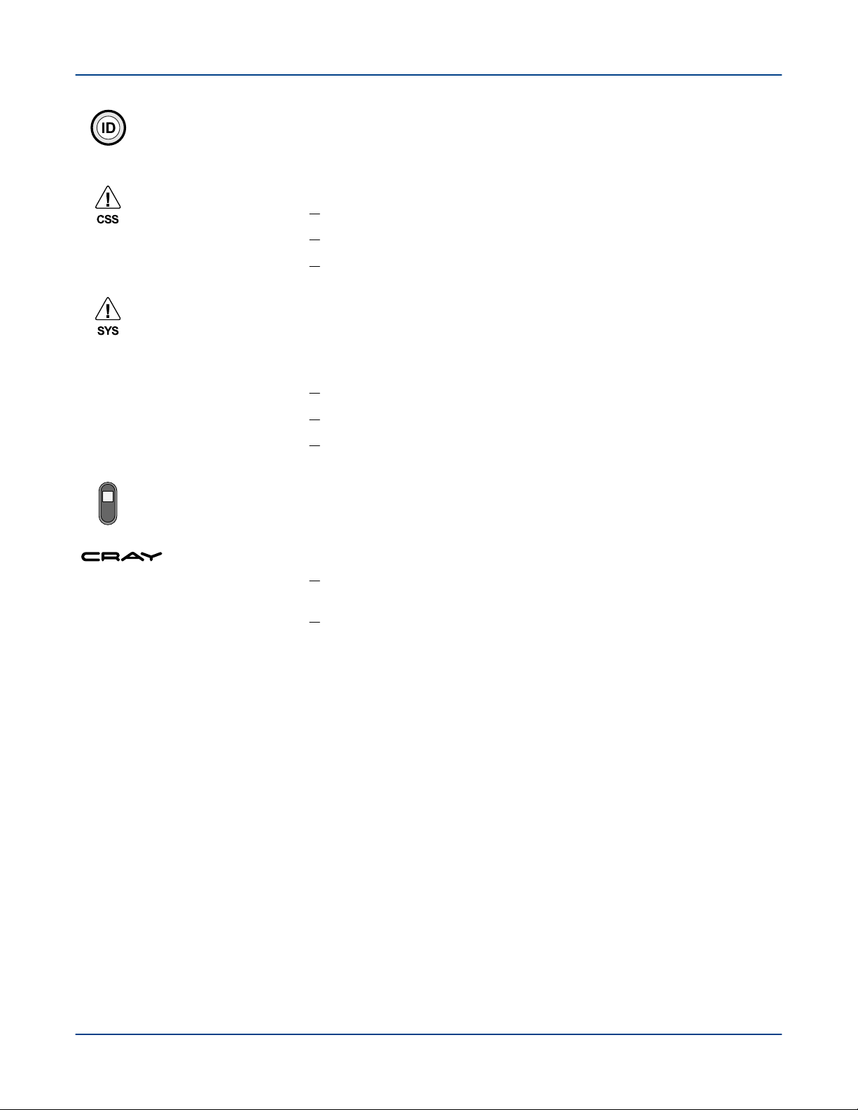
System ID button [white]. This LED lights white to visually identify a specific server within
a rack/cabinet. The System ID button toggles the state of the LED. If the LED is off, pushing
the System ID button lights the ID LED. It remains lit until the button is pushed again or until
a chassis identify command is received to change the state of the LED.
Chassis health (CSS) LED [amber]. The chassis health LED indicates:
System health (SYS) LED [amber]. The system status LED indicates a fatal or non-fatal
error in the system as reported through the BMC or by the management daughter card
(MDC). The System Status LED is set to a steady amber color for all fatal errors that are
detected during processor initialization. A steady amber color indicates that an
unrecoverable system failure condition has occurred:
Synchronize switch. This switch sets/synchronizes the CRAY logo to display the same
conditions as the CSS LED. Synchronize is on (default) when the switch is in the up
position, as shown.
CRAY logo [blue/amber].
GPU and PCIe Status Indicators
The front panel has a series of LED status indicators that are used to quickly identify issues. The 20 LEDs on the
right side provide GPU status from the PCIe switch board.
H-6150 (Rev C) 15
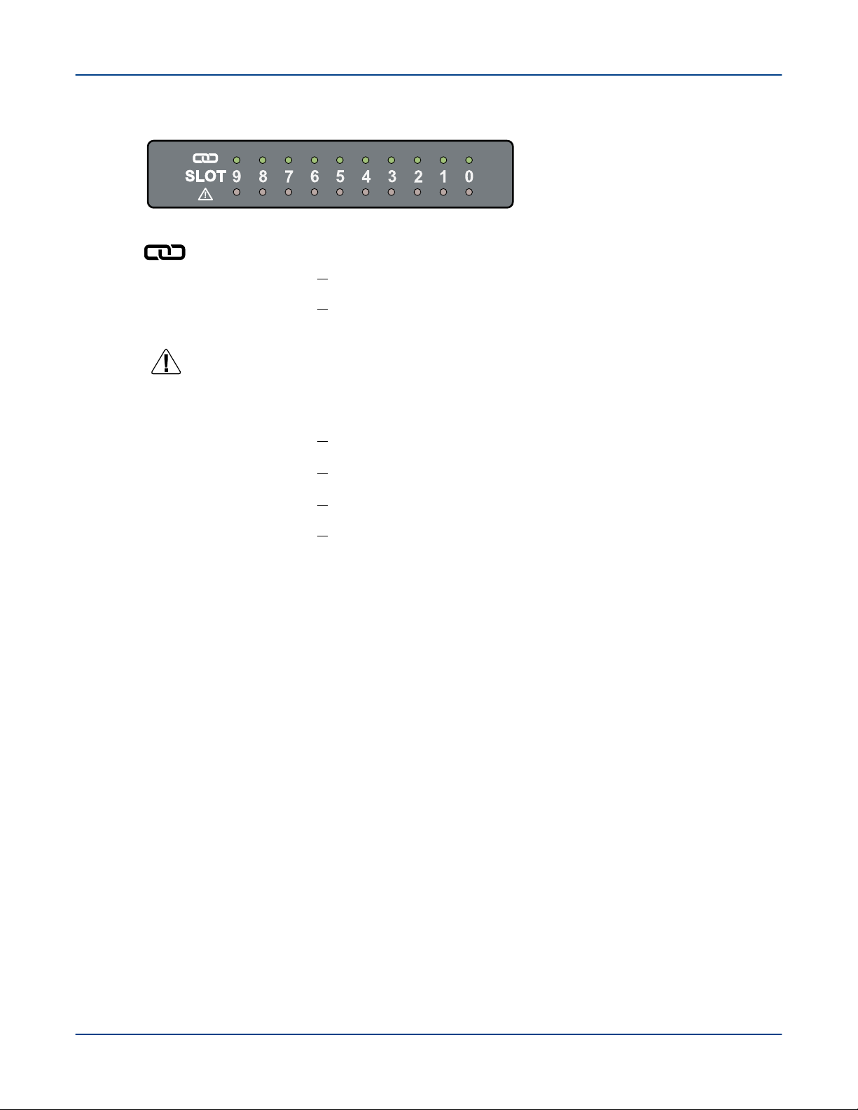
Figure 6. GPU and PCIe LEDs - CS-Storm 500GT
= GPU Status LEDs
= PCIe Status LEDs
Off
Normal operation
Solid (red)
Fatal alarm. Indicates over temperature, over current,
or communication error.
Off No link or GPU is not detected.
On (red) PCIe link is up (8.0 GT/s - Gen3).
Blinking (2 Hz) PCIe link is up (5.0 GT/s - Gen2).
Blinking (1 Hz) PCIe link is up (2.5 GT/s - Gen1).
These LEDs indicate the status and transfer speed for the PCIe connection
through the PCIe (PLX) switch to the GPU.
.
Server Components
H-6150 (Rev C) 16
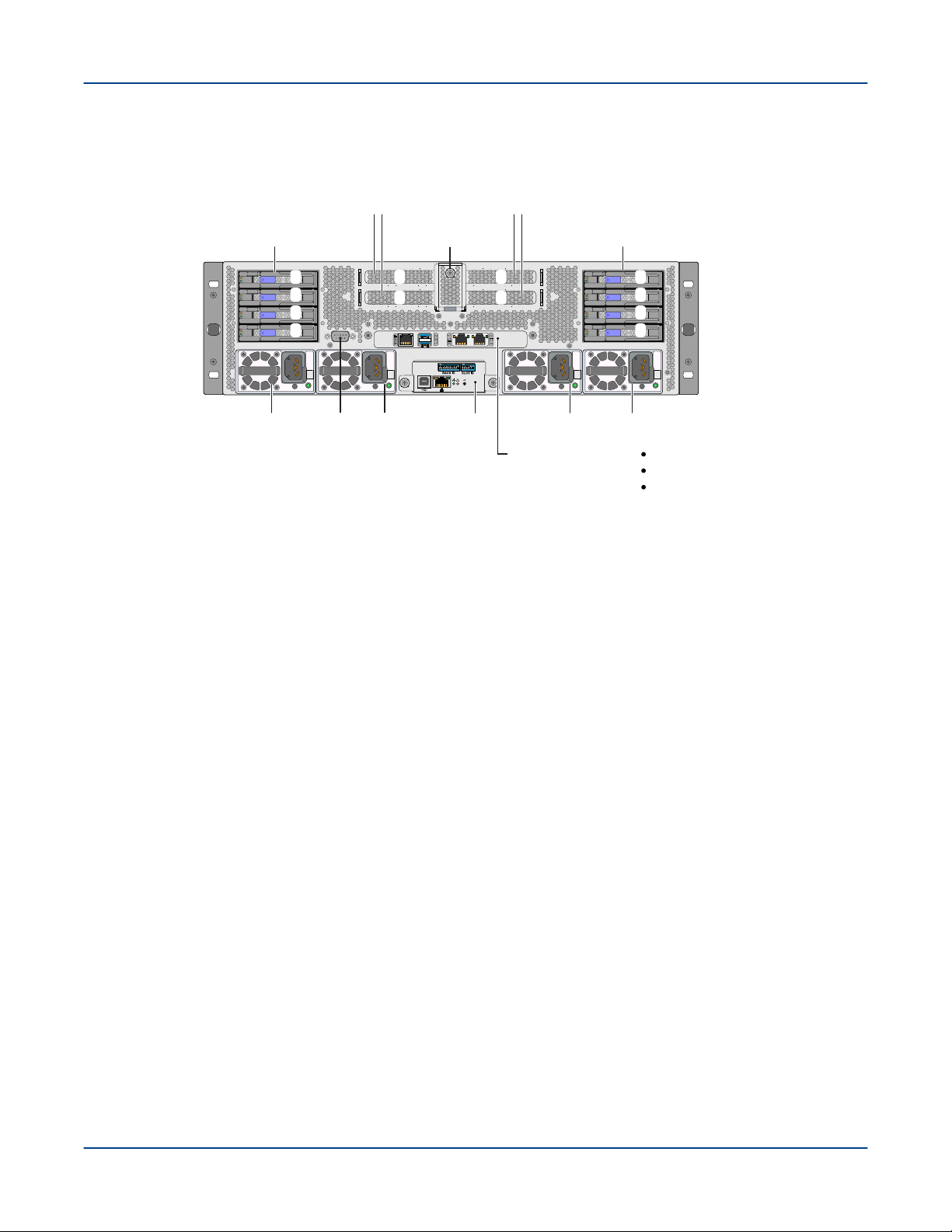
Rear PCIe Slots, I/O Connectors, and LEDs
Drive bay 1
(Drive slots 0-3, SATA)
PSU 0
PCIe card latch
0
1
2
3
4
5
6
7
PSU 1 PSU 2 PSU 3VGA
(DB15)
4 PCIe 3.0, x16 slots
(half-height, half-length)
Management
daughter
card (MDC)
assembly
Motherboard ports:
Dual USB 3.0 (stacked)
Dedicated management port
NIC 1 / NIC 2
1
2
3
4
Drive bay 2
(Drive slots 4-7, SATA/NVMe)
The number of drives and PCIe cards can vary
depending on server PCIe and GPU configuration.
Note:
Figure 7. Rear Controls and Connectors - CS-Storm 500GT
Server Components
Four PCIe 3.0 slots
The low-profile card slots support use of add-in cards with standard low-profile brackets. No
customized brackets are required. The PCIe card release closes to secure the cards in
place and opens to release tension so cards can be added/replaced. A thumbscrew secures
the PCIe card release in place.
● Dual rail configuration (default) – PCIe 3.0 slots 1 and 2.
● Quad rail configuration (optional) – PCIe 3.0 slots 1-4. Additional slots 3 and 4 come
from the center slots of the PCIe switch board through twin-axial (twin-ax) ribbon cable
assemblies.
VGA (DB15) optional
The optional VGA port is implemented through a 12-pin ribbon cable connection to the
motherboard (default).
Management Daughter Card (MDC)
The MDC is used to configure, monitor, and manage server subsystems and components.
Primary maintenance functions include fan and thermal monitoring and power consumption
monitoring. Refer to Management Daughter Card (MDC) on page 35 for details.
Drive Support and Configuration
The flexible design of the CS-Storm 500GT server enables numerous storage configuration options. The following
two drive configurations are offered as standard options. Other drive configurations will be considered upon
request:
H-6150 (Rev C) 17

Server Components
● 8 SATA drives
○ Bay 1 - 4 SATA
○ Bay 2 - 4 SATA
● 4 SATA and 4 NVMe drives
○ Bay 1 - 4 SATA
○ Bay 2 - 4 NVMe (requires NVMe cables from slots 2 and 3)
NVMe Support
● Drive bay 2 supports up to 4 NVMe drives
Internal SATA SSD Drives
● Up to 2 internal fixed SATA SSDs are supported, with different cabling and/or changes to drive support in bay
2.
● This drive bay does not have a disk backplane. The drives are cabled directly to power and SATA cables in
the chassis.
H-6150 (Rev C) 18
 Loading...