

Cray ClusterStor L300, ClusterStor L300N Installation Manual

ClusterStor™ L300 and L300N Field
Installation Guide
(3.0.0)
H-6163

Contents
Contents
1 About the ClusterStor L300 and L300N Field Installation Guide............................................................................5
2 Install a ClusterStor L300 and L300N System........................................................................................................7
3 Prerequisites to Installation.....................................................................................................................................9
3.1 Service Area Clearances.........................................................................................................................10
3.2 Plan for Rack Position.............................................................................................................................11
3.3 Safe Handling and Precautions Check List.............................................................................................12
4 Uncrate the ClusterStor L300 and L300N Rack...................................................................................................15
5 Move the Rack to its Final Position.......................................................................................................................17
6 Install Disk Drives in a 5U84 Enclosure................................................................................................................19
7 Install Disk Drives in a 2U24 Enclosure................................................................................................................25
8 Cable the External Power Connections................................................................................................................27
8.1 Reset the Circuit Breaker........................................................................................................................31
8.2 Reset a Circuit Breaker on a Raritan PDU..............................................................................................31
9 Standardized Rack Configurations.......................................................................................................................34
10 Cable Inter-rack Local Management Network (LMN).........................................................................................36
11 Environment Connections...................................................................................................................................38
11.1 Cable SMU and 36-Port InfiniBand EDR LDN with Dual 24-Port LMN Switches..................................38
11.2 Cable SMU and 36-Port InfiniBand EDR LDN with Dual 48-Port LMN Switches..................................40
11.3 Cable SMU and 36-Port 40GbE LDN and Dual 24-Port LMN Switches................................................41
11.4 Cable SMU and 36-Port 40GbE LDN with Dual 48-Port LMN Switches...............................................43
11.5 Cable SMU and 24-Port Omni-path LDN with Dual 24-Port LMN Switches..........................................45
11.6 Cable SMU and 24-Port Omni-path LDN Dual 48-Port LMN Switches.................................................46
11.7 Cable SMU and Omni-path 48-Port LDN with Dual 24-Port LMN Switches..........................................48
11.8 Cable SMU and Omni-path 48-Port LDN with Dual 48-Port LMN Switches..........................................50
11.9 Cable SMU and 36-Port 100GbE LDN with Dual 24-Port LMN Switches.............................................52
11.10 Cable SMU and 36-Port 100GbE LDN with Dual 48-Port LMN Switches...........................................54
12 Power on the System..........................................................................................................................................56
13 Perform the First-Run Configuration...................................................................................................................65
13.1 Create the Administrator Password.......................................................................................................65
13.2 Configure the Lustre Network Interfaces...............................................................................................68
13.3 Troubleshoot the Lustre Network Screen..............................................................................................69
13.4 Run Lustre Validation Tests...................................................................................................................71
13.4.1 Run Lustre Validation Tests -- Lustre Not Mounted..................................................................73
13.4.2 Troubleshoot the Lustre Validation Tests..................................................................................73
13.5 Monitor Progress Screen.......................................................................................................................76
2

Contents
13.6 Review the Complete Screen................................................................................................................77
13.7 Specify Lustre User Authentication.......................................................................................................78
13.7.1 Specify Lustre User Authentication via the Active Directory Screen ........................................79
13.7.2 Specify Lustre User Authentication via the LDAP Screen........................................................80
13.7.3 Specify Lustre User Authentication via the NIS Screen...........................................................84
13.7.4 Specify Lustre User Authentication via the Local Screen.........................................................85
13.7.5 Troubleshoot the Lustre Users Screen.....................................................................................86
13.8 Post-Install Checkout.............................................................................................................................86
13.9 Test Client Mount of Lustre File System................................................................................................87
14 Configure SMTP Relay, RAS Email, Remote Support, and Service Console.....................................................91
15 Configure an Additional MMU to Support DNE...................................................................................................94
16 Reference...........................................................................................................................................................95
16.1 Power Off the ClusterStor L300 and L300N with CSCLI.......................................................................95
16.2 Power Off the ClusterStor L300 and L300N System via CSSM............................................................96
16.3 Internal Rack Cabling Reference...........................................................................................................97
16.3.1 ClusterStor L300 and L300N SMU Physical and Logical Port Numbering...............................99
16.3.2 ClusterStor L300 and L300N MMU Physical and Logical Port Numbering............................100
16.3.3 Cable AMMU SAS 1U Servers...............................................................................................101
16.3.4 ClusterStor L300 and L300N SSU Physical and Logical Port Numbering.............................101
16.3.5 Internal Rack Cabling - Local Management Network.............................................................102
16.3.6 Internal Rack Cabling - Local Data Network..........................................................................107
16.3.7 Cable an Optional Additonal MMU.........................................................................................115
16.3.8 Cable SSU ESU SAS Ports....................................................................................................116
16.3.9 Cable AMMU Networks..........................................................................................................118
16.4 Component Descriptions.....................................................................................................................119
16.4.1 Embedded Application Controller (EAC)................................................................................119
16.4.2 Operator Control Panel - 5U84...............................................................................................121
16.4.3 Operator Control Panel - 2U24...............................................................................................123
16.5 Power Diagrams..................................................................................................................................124
16.5.1 Base Rack Standard Power Distribution for PX2-5965X3-V2................................................124
16.5.2 Base Rack Inverted Power Distribution for PX2-5965X3-V2..................................................124
16.5.3 Storage Rack Optional MMU Standard Power Distribution for PX2-5965X3-V2....................125
16.5.4 Storage Rack Optional MMU Inverted Power Distribution for PX2-5965X3-V2.....................126
16.5.5 Base Rack Standard Power Distribution for PX2-5104X2-V2................................................127
16.5.6 Base Rack Inverted Power Distribution for PX2-5104X2-V2..................................................128
16.5.7 Storage Rack Optional MMU Standard Power Distribution for PX2-5104X2-V2....................129
16.5.8 Storage Rack Optional MMU Inverted Power Distribution for PX2-5104X2-V2.....................130
16.5.9 Base Rack Standard Power Distribution for PX2-5100X2-V2................................................131
3

Contents
16.5.10 Base Rack Inverted Power Distribution for PX2-5100X2-V2................................................132
16.5.11 Storage Rack Optional MMU Power Distribution for PX2-5100X2-V2.................................133
16.5.12 Storage Rack Optional MMU Inverted Power Distribution for PX2-5100X2-V2...................134
16.5.13 Base Rack Standard Power Distribution for PX2-5551-N4V2..............................................135
16.5.14 Base Rack Inverted Power Distribution for PX2-5551-N4V2...............................................136
16.5.15 Storage Rack Optional MMU Standard Power Distribution for PX2-5551-N4V2.................137
16.5.16 Storage Rack Optional MMU Inverted Power Distribution for PX2-5551-N4V2...................138
16.5.17 Base Rack Optional AMMU Standard Power Distribution for PX2-5965X3-V2....................139
16.5.18 Base Rack Optional AMMU Standard Power Distribution for PX2-5104X2-V2....................140
16.5.19 Base Rack Optional AMMU Standard Power Distribution for PX2-5100X2-V2....................140
16.5.20 Base Rack Optional AMMU Standard Power Distribution for PX2-5551-N4V2...................141
16.5.21 Base Rack Optional AMMU Inverted Power Distribution for PX2-5965X3-V2.....................142
16.5.22 Base Rack Optional AMMU Inverted Power Distribution for PX2-5104X2-V2.....................143
16.5.23 Base Rack Optional AMMU Inverted Power Distribution for PX2-5100X2-V2.....................144
16.5.24 Base Rack Optional AMMU Inverted Power Distribution for PX2-5551-N4V2.....................144
4
About the ClusterStor L300 and L300N Field Installation Guide
1
About the ClusterStor L300 and L300N Field
Installation Guide
The ClusterStor™ L300 and L300N Field Installation Guide H-6163 includes instructions for setting up,
configuring, and testing a ClusterStor L300 or L300N storage system.
Release 3.0.0 Information
This version includes procedures to support Cray software release 3.0.0.
Table 1. Record of Revision
Publication Title Date Updates
ClusterStor L300 and L300N Field Installation Guide
(3.0.0) H-6163
Related Publications
Additional documentation for ClusterStor L300 and L300N systems is available from pubs.cray.com.
● ClusterStor L300/L300N Cabling Guide
● Lustre® Client Software Build and Installation Guide for Cray® Cluster Connect™ S-2550
January 2018 Initial release of 3.0.0
version.
● XC™ Series Lustre® Administration Guide S-2648
Scope and Audience
This publication is written for trained Cray technicians and provides instructions to unpack and install a
ClusterStor L300 and L300N system at the customer site. It does not include information about daily operation.
Typographic Conventions
Monospace
Monospaced Bold
Oblique or Italics Indicates user-supplied values in commands or syntax definitions.
Proportional Bold Indicates a GUI Window, GUI element, cascading menu (Ctrl→Alt→Delete), or
\ (backslash) At the end of a command line, indicates the Linux® shell line continuation character
Indicates program code, reserved words, library functions, command-line prompts,
screen output, file/path names, and other software constructs.
Indicates commands that must be entered on a command line or in response to an
interactive prompt.
key strokes (press Enter).
(lines joined by a backslash are parsed as a single line).
5

About the ClusterStor L300 and L300N Field Installation Guide
Trademarks
The following are trademarks of Cray Inc. and are registered in the United States and other countries: CRAY and
design, SONEXION, URIKA, and YARCDATA. The following are trademarks of Cray Inc.: APPRENTICE2,
CHAPEL, CLUSTER CONNECT, ClusterStor, CRAYDOC, CRAYPAT, CRAYPORT, DATAWARP, ECOPHLEX,
LIBSCI, NODEKARE. The following system family marks, and associated model number marks, are trademarks
of Cray Inc.: CS, CX, XC, XE, XK, XMT, and XT. The registered trademark LINUX is used pursuant to a
sublicense from LMI, the exclusive licensee of Linus Torvalds, owner of the mark on a worldwide basis. Other
trademarks used in this document are the property of their respective owners.
6

Install a ClusterStor L300 and L300N System
2
ClusterStor L300 and L300N systems are scale-out Lustre® storage solutions that support InfiniBand™ (EDR,
FDR), 40/100 GbE, and Intel Omni-Path (OPA) as well as a broad number of popular of Linux distributions
through the Lustre Client by Cray.
Procedures include unloading and unpacking the system at the customer site, cabling the system into the
installation environment, powering on the system, running the CSM configuration wizard, and running connectivity
and performance tests.
Additionally, this document contains a section on common installation problems (including workarounds) and
troubleshooting information.
The installation process consists of the following procedures:
1. Complete the pre-installation checklist
2. Unload the shipping crates
3. Uncrate the cabinet(s)
4. Move each rack into position
5. Install the disk drives
6. Cable the system
7. Power on the system
8. Perform the first-run configuration
9. Perform the advanced MMU (AMMU) installation procedure, If the system being installed includes an AMMU.
Install a ClusterStor L300 and L300N System
The figure shows an each of the ClusterStor L300 and L300N networks:
● Lustre client network (LCN) - Customer Lustre client network:
○ InfiniBand EDR
○ 40 GbE
● External administration network (EAN) - Customer administration network.
● Local management network (LMN) – Dual-bonded GigE local management private network
● Local data network (LDN) - Dual fault-tolerant local data network with external uplinks. EAC 0 in each SMU,
MMU, and SSU is connected to LDN 0 switch, and EAC 1 is connected to LDN 1 switch.
7

Figure 1. ClusterStor L300 and L300N Networks Overview
SMU
Base MMU
SSU
OSS OSS
LMN LDN
LCN
RAS Service Ports
Base Rack
LMN To
Storage
Rack(s)
(x500)
*AD/LDAP/NIS server must be same on all networks
External administration network (EAN)
Local data network (LDN)
EAN
MDS/MGSMDS/MGS
MGMT 0
MGMT 1
(x1)
(x1)
(x1)
Lustre Client
Network (LCN)
Local management network (LMN)
Lustre client network (LCN)
unspecified network connection
Customer client node
Customer server node
Server node
Chassis
AMMU
MDS/MGSMDS/MGS
EAC 1
EAC 0
EAC 0 EAC 1
EAC 0 EAC 1
EAC 0 EAC 1
LMN Switch 0
LMN Switch 1
LDN Switch 1
LDN Switch 0
PDU
A
PDU
B
Lustre Clients
(x 1000s)
Lustre Client Network
Core Switch
AD/LDAP/NIS server*
CSM Administrator
Station
AD/LDAP/NIS server*
NTP server
DNS server
SMTP server
Install a ClusterStor L300 and L300N System
8

Prerequisites to Installation
3
Verify that these prerequisites have been satisfied before installing the ClusterStor L300 and L300N system.
Acclimate the System Cabinets
Inspect the System
Forklift Size Requirements
Rack Weight and Dimensions
Prerequisites to Installation
When the system is unloaded from the climate controlled truck, the shipping environment
temperature will be close to the computer room. If the system has been stored in an
environment that is significantly colder than the environment in which it will be installed (15
°F [8 °C] or greater disparity), leave the system cabinets in their shipping configuration for at
least 24 hours at room temperature. This prevents damage to the equipment from thermal
shock and condensation.
Cray has provided the pre-configured rack: built, configured, and tested to the valid
configuration ordered.
● 10 ton (9,072 kg) minimum lifting capacity
● Forklift with tine side travel is strongly recommended
If the system cabinets do not fit through all access doors, you may need to uncrate the
system cabinets as described in Uncrate the ClusterStor L300 and L300N Rack on page
15 in a secure (dry) staging area. Check the flooring on the entire path from the truck or
staging area to the computer room. Be sure the flooring can:
● Support the weight of the system cabinet
● Allow the cabinet to roll, or if aluminum plates are required
● Will not be damaged during the installation
Table 2. Rack Weight and Dimensions
Aluminum Plates
Aluminum plates may be required to roll the system across uneven flooring, thresholds,
carpeting, or other obstacles. Angle the cabinet when rolling it over the edge of the
aluminum plate so that only 1 wheel makes contact with the plate.
Height: 78.40in (1991 mm)
Width: 23.60in (600 mm)
Depth: 47.25in (1200mm)
Weight: Maximum 2513 lbs. (1140 kg)
Weight: Shipping 1720 lbs. (780 kg)
9

Infrastructure is Present
Access to corporate switch (Intranet)
KVM or monitor/keyboard to set up ethernet port
Browser access (from a separate system with a 1024 x 768 monitor)
Cables at lengths sufficient to connect the system to the user environment
● Ethernet
● InfiniBand, Omni-Path (OPA), 40GbE, or 100GbE (depending on the configuration)
Tools
13mm socket wrench
T10 and T20 Torx screwdrivers
Pozidriv screwdriver
61mm/24 inch spirit level (optional)
Work gloves, safety shoes
Personnel
2 people are required for the unpacking process
2 people (minimum) are required to move the rack from the pallet and into its final position
1 person is required to configure and provision the system software
System Updates
SU10
System Access Requirements
Most ClusterStor L300 and L300N software procedures and CSCLI commands require
access to the administrative (admin) user account. However, root access is required to
perform the system installation procedure. Contact Cray Support for root access.
Prerequisites to Installation
3.1
Before unpacking the ClusterStor L300 and L300N system crate and beginning the installation, verify that
recommended service area clearances are available and that personnel are aware of the safe handling
procedures and precautions.
The top of the rack has cutout holes for cables to be passed into the rack. If cables are to be passed into the rack
from underneath the floor, the recommended cutout is 152.4 mm x 152.4 mm (6 inches x 6 inches) in the rear of
the tile on which the rack is positioned.
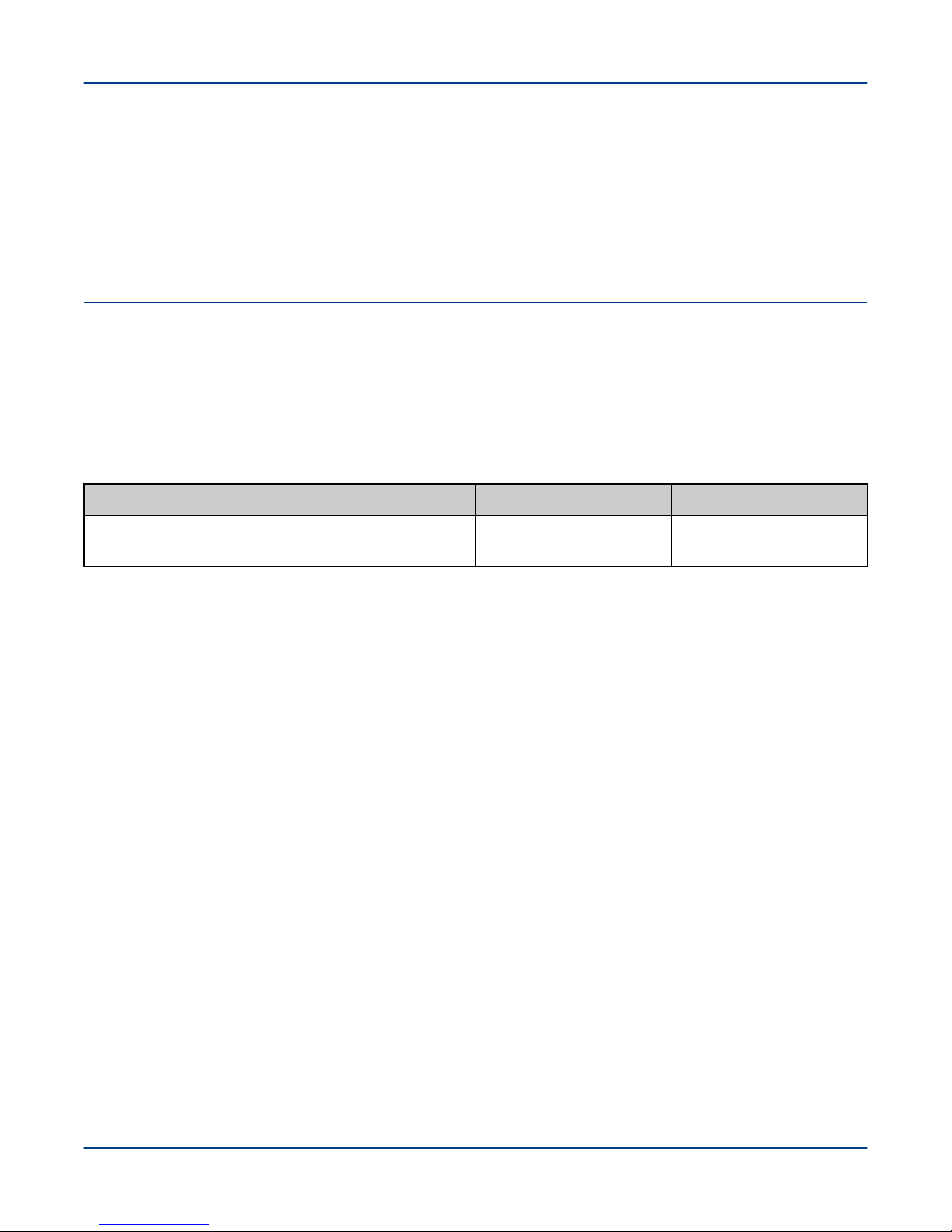
Verify that the recommended service area clearances are available at the installation location as shown:
● 45.3in (1150 mm) from the front of the rack
● 25.6 inches (650 mm) from the rear of the rack
● 16.5 inches (420 mm) and 23.6 inches (600 mm) on the side of the rack
Service Area Clearances
10
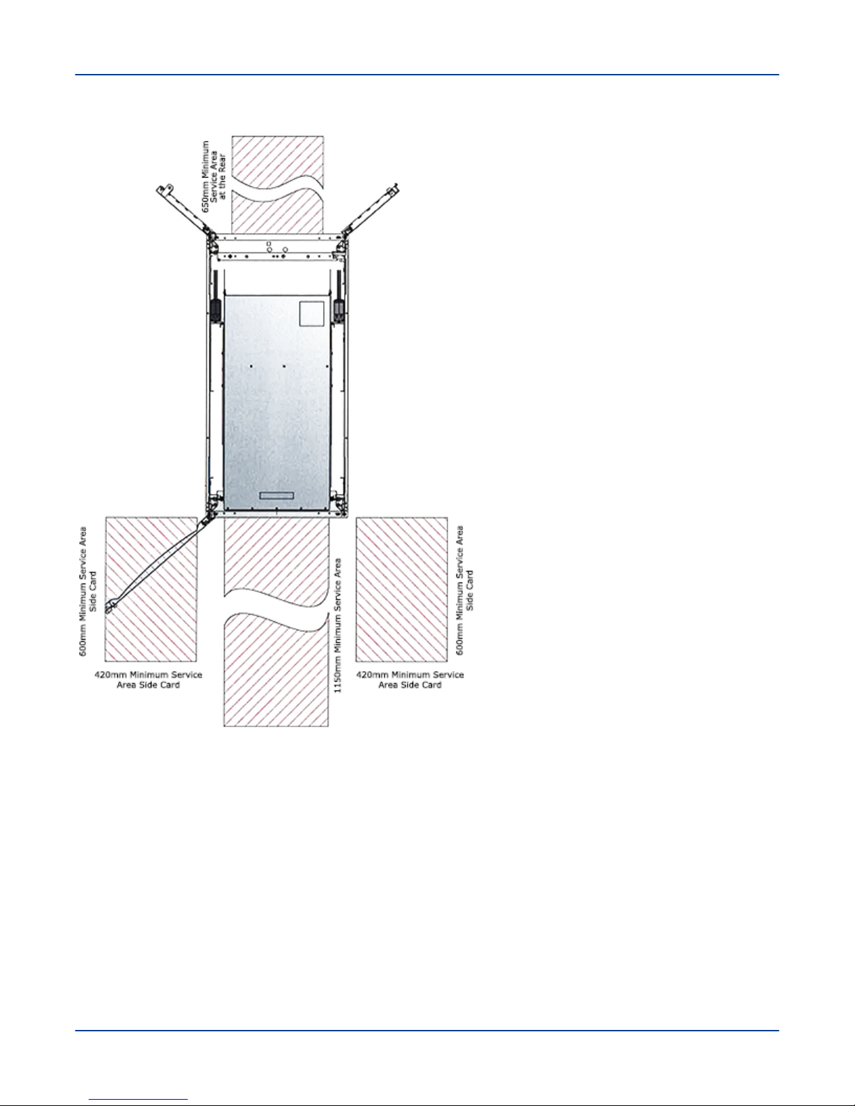
Figure 2. Rack Service Area Clearance
Prerequisites to Installation
3.2 Plan for Rack Position
When unpacking and assembling a multi-rack ClusterStor L300 and L300N system, carefully plan the order to
unpack and assemble the racks.
The base rack (either as a stand-alone shipment or part of a system) is identified with “R1” & “BASE,”.
Storage racks installed in manufacturing test alongside the base rack are numbered sequentially "R2" to "Rn"
where n is the highest number that was physically installed with the base rack at the factory, as shown.
Storage racks that were not installed or tested with the base rack are numbered sequentially, following the last
base rack install number. SSUs are also labeled accordingly for each rack.
11
IMPORTANT: To determine which storage racks were built with the base rack and which were not and
other configuration information, refer to the Storage Configuration Document (SCD) shipped with the
system.
Figure 3. SSU Rack Labeling
Prerequisites to Installation
3.3 Safe Handling and Precautions Check List
Before unpacking the ClusterStor L300 and L300N system, complete this prescribed checklist and observe the
stated precautions.
CAUTION: Read and understand these instructions completely before starting any physical installation
activity.
CAUTION:
● Electro-static Sensitive Devices (ESD)
● Observe all ESD precautions when handling disk drives or components, and avoid touching the
printed circuit boards.
12

Prerequisites to Installation
WARNING:
● Crushing hazard
● The ClusterStor L300 and L300N rack weighs up to 2513 lbs. (1140 kg). It is possible for the rack to
tip over while it is being moved. Do not lean the rack more than 5 degrees from a level surface or
when rolling down an incline or ramp.
● Visually inspect the shipping crate for damage.
● Verify that the area near the pallet is clear of any trip hazards, people or obstacles while rolling the rack down
the ramp.
● If any inspection fails, do not continue. Contact Cray Support.
WARNING:
● Electrical hazard
● The ClusterStor L300 and L300N rack has multiple input power connectors. Disconnect all supply
power for complete isolation prior to installation. Failure to do so can result in serious personal injury.
WARNING:
● Personal injury or equipment/property damage
● The floor must support a static load rating of 1720 lbs. (780 kg) in the shipping configuration and a
maximum load rating of 2513 lbs. (1140 kg) fully populated.
WARNING:
● Personal injury or equipment/property damage
● The rack side panels can potentially be a hazard when they become unlatched. It is recommended
that the side panels remain locked during normal operations.
WARNING:
● Personal injury or equipment/property damage
● After the ClusterStor L300 and L300N rack is removed from the crate pallet, always populate the
bottom two SSUs with disk drives before moving the rack to its final location.
WARNING:
● Serious Injury or Equipment Damage
● Always perform a ground (earth) continuity and insulation test after completing the hardware
installation and prior to powering on the system.
● When loading the rack, fill from the bottom up and empty from the top down.
● Do not slide more than one drawer out of the enclosure at a time to avoid the danger of the rack toppling over.
● This equipment must be installed on a dedicated circuit.
● The customer is responsible for ensuring that the power to each power distribution unit (PDU) is independent
and presents no compromise to the independent redundant nature of the power system.
13

Prerequisites to Installation
● The dedicated circuit must have circuit breaker or fuse protection. The PDUs provide handle-type circuit
breakers. Adequate protection must be provided for the dedicated power circuit. Protection of capacity equal
to the current rating of the distribution unit must be provided and must meet all applicable codes and
regulations.
● The plugs on the PDUs shall be installed near the equipment and shall be easily accessible.
● Frame load ratings are not dependent on side panels, doors, or other components for structural support.
14
Uncrate the ClusterStor L300 and L300N Rack
4
Uncrate the ClusterStor L300 and L300N Rack
Prerequisites
See Prerequisites to Installation on page 9 and make sure flooring can support the shipping configuration of the
rack at 1720 lbs (780 kg), can enable the cabinet to roll, and will not be damaged.
About this task
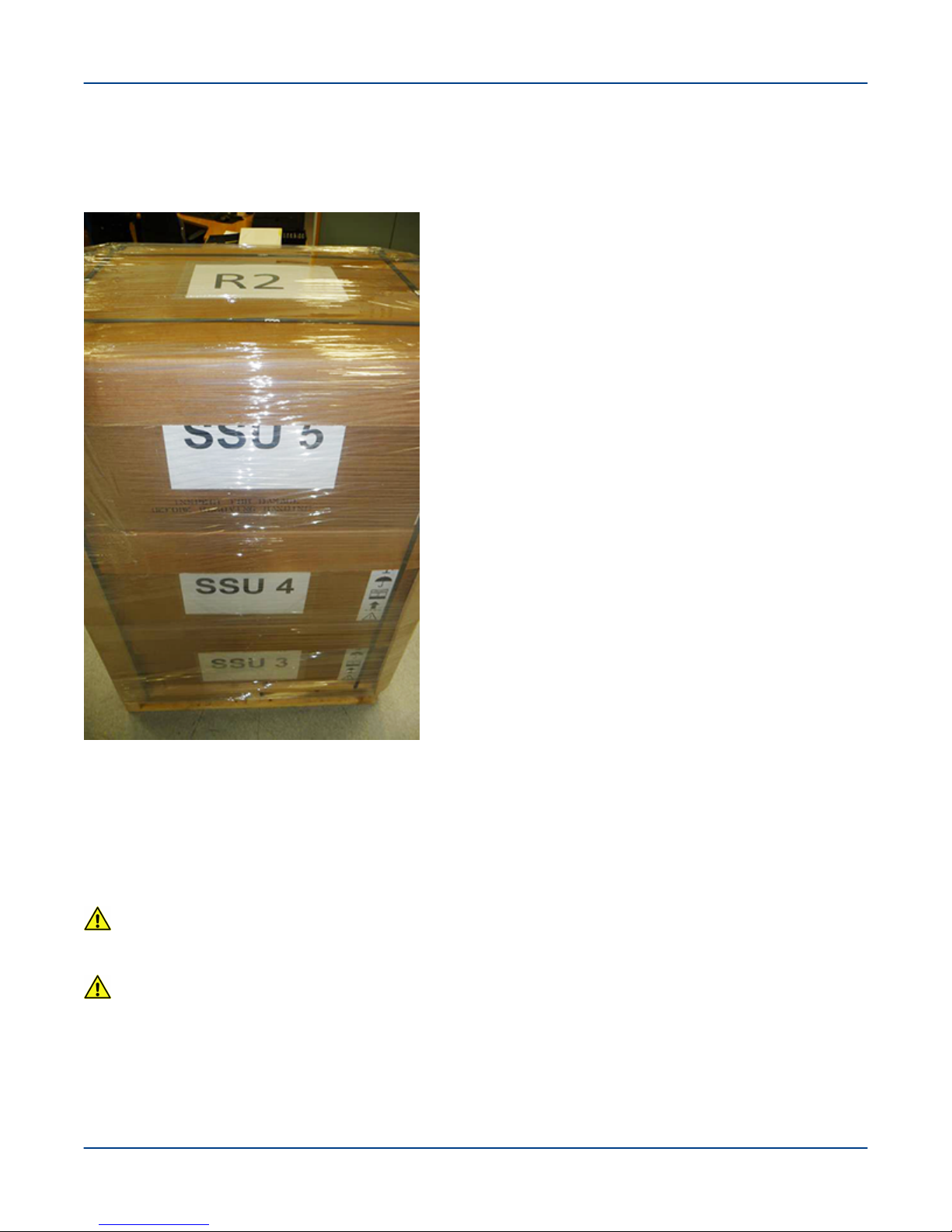
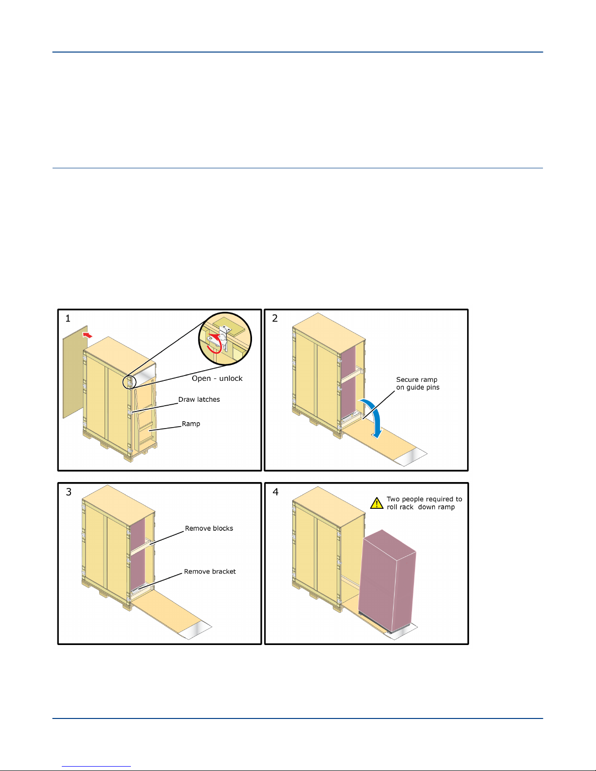
This task describes how to safely remove the ClusterStor L300 and L300N rack from the shipping crate. Two
people are required to safely roll the rack off the pallet ramp.
Figure 4. Uncrate the Rack
15

Uncrate the ClusterStor L300 and L300N Rack
Procedure
1. Use a pallet jack to position the crate so that there is adequate space to roll the rack down the ramp.
2. Unlock the draw latches that secure the rear panel to the crate.
Video:
Refer to the Uncrate a 19in APC Rack service video: 00:001:14.
3. Unlock the draw latches that secure the front panel ramp to the crate, remove the front panel and position the
ramp securely on the crate guide pins.
IMPORTANT:
4. Position one trained person in front of the rack to guide it an slow its decent.
5. Position the other trained person behind the rack to push.
CAUTION:
● Personal Injury or Damage to Equipment
● The rack weighs 1720 lbs (780kg) in its shipping configuration. Momentum can carry it down the
ramp quickly. Be sure the cabinet casters stay centered over the ramp rails when the cabinet rolls
down the ramp. Failure to do so could result in personal injury or equipment damage.
6. Carefully roll the rack off the ramp slowly in a straightforward direction.
7. When the rack is clear of the ramp, stop its movement.
16

Move the Rack to its Final Position
5
Move the Rack to its Final Position
Prerequisites
Procedures
The ClusterStor L300 and L300N rack has been unpacked, rolled down the ramp, and the
lower two SSUs are populated with disk drives.
Tools
Bubble level
Pozidriv (or Philips) screwdriver and the two bolts provided to secure the outrigger bracket
Personnel
Two TRAINED personnel are required to complete this task.
Aluminum Plates
Aluminum plates may be required to roll the system across uneven flooring, thresholds,
carpeting, or other obstacles. Angle the cabinet when rolling it over the edge of the
aluminum plate so that only 1 wheel makes contact with the plate.
About this task
WARNING:
● Personal Injury or Equipment Damage
● If the rack is fully populated with SSUs and equipment, install disk drives in the lower SSUs to lower
the center of gravity and reduce the tipping hazard.
Procedure
1. Install the disk drives in the lower one or two SSUs before moving the rack to its final position to reduce the
rack tipping hazard. See Install Disk Drives in a 5U84 Enclosure on page 19.
2. Move the rack as close as possible to its final location.
WARNING:
● Personal Injury or Equipment Damage
● Do not push the rack from the side. Always push the rack from the front or rear.
17

Move the Rack to its Final Position
Figure 5. No Side Push Label
IMPORTANT: The rack may only be moved up or down a maximum incline/decline of 5 degrees.
3. Position the rack to its final location and lower the leveling feet using a 13mm wrench.
4. Use a bubble level to verify the rack is level.
5. From the bottom up, repeat the steps above to insert the disk drives into the remaining enclosures. See Install
Disk Drives in a 5U84 Enclosure on page 19 and Install Disk Drives in a 2U24 Enclosure on page 25.
18

Install Disk Drives in a 5U84 Enclosure
6
Install Disk Drives in a 5U84 Enclosure
Prerequisites
The ClusterStor L300 and L300N rack has been unpacked, and moved at least off the pallet and down the ramps
to the floor. It may already be located in its final operating position.
About this task
How to install disks in a ClusterStor L300 and L300N 5U84 enclosure (SSU).
IMPORTANT: Disk drives are labeled and they must be installed in the exact order and in the exact slots
where they were installed at the factory.
Typically, 5U84 enclosures are shipped empty and must be populated at installation, particularly the lower two
enclosures in a rack, which must be populated before safely moving the rack from the bottom of the ramps to its
final destination.
There are two methods of loading disks: using the speedloader device, which loads seven disks at once to speed
disk population, and the manual method, which loads one disk at a time. Both methods are described in this
procedure.
CAUTION:
● EQUIPMENT OVERHEATING
● All drive slots must have a disk drive carrier module or a dummy carrier module installed to maintain a
balanced airflow.
CAUTION:
● EQUIPMENT DAMAGE OR PERSONAL INJURY
● To ensure rack stability, open only one drawer in a 5U84 (SSU) enclosure at a time. Do not open
multiple drawers at the same time.
CAUTION:
● EQUIPMENT DAMAGE
● Observe ESD precautions when handling this equipment. Failure to do so can result in equipment
damage.
Procedure
1. Refer to the packaging documentation to locate the marked carton containing the drives for the target 5U84
enclosure.
19

Install Disk Drives in a 5U84 Enclosure
2. Install the disks in the same location they were in at the factory by referencing the drive numbers, orientation
(front/back, upper/lower), or SSD designation provided by manufacturing on the shipping container.
From the front of the container, drive 0 is in the lower-left slot drive 41 in the upper-right slot. Drive 42 is in
the lower-slot, drive 83 in the upper-right slot.
Figure 6. Disk Drive Shipping Container
Choose to use either the speedloader multiple-disk method or the individual-disk method to install the disk
drives.
3. Use a T-20 Torx screwdriver to unlock the two drawer latches on the front of each drawer in the lowest empty
5U84 enclosure. Pull open the lower drawer.
4. For Any Disk Installation Situation: Install the disk drives in the lowest empty 5U84 (SSU) enclosure
drawer.
Always begin from the lowest empty drawer, and populate the drives from the rear drive slots to the front drive
slots (numerically from highest to lowest), then working upward to the next empty drawer.
NOTE: The two drive carriers with SSD drives install in slots 28 and 70.
20
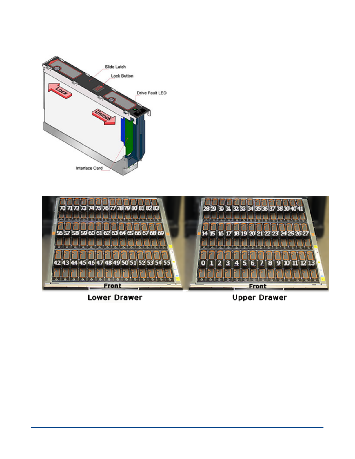
Figure 7. Disk Drive in Drive Carrier
Figure 8. 5U84 Drive Slot Locations
Install Disk Drives in a 5U84 Enclosure
NOTE: The two drive carriers with SSD drives install in slots 28 and 70.
5. Close the first drawer, open the drawer above it, and populate it with disk drives from the rear slots to the front
slots, as before.
6. Repeat the process for the remaining 5U84 enclosures, working upwards.
Individual Disk Load Method
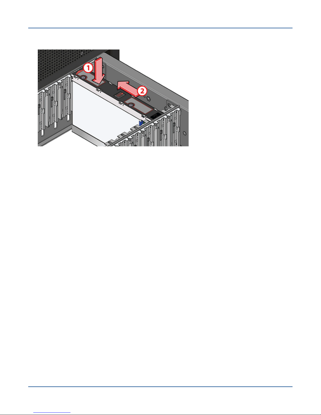
7. To manually install disk drives, remove the correct disk drive from the box of drives and slide the lock button
to the right (unlocked position), as shown.
Verify that the slide lock is in the unlocked position and that each disk is installed in the position in which it
was installed at the factory.
21
Install Disk Drives in a 5U84 Enclosure
Figure 9. Install the Disk Individually
8. Starting with the lower drawer in the lowest empty 5U84 enclosure, open the drawer and begin populating the
drives from rear to the front, starting with slot labeled “83” and work towards the slot “42.”
9. Carefully slide each drive down into position and press down while sliding the latch to the locked position,
towards the rear of the enclosure as shown.
Move the lock button to the left to verify that it has reset.
10. Press the button on each drawer slide to release the drawer, then slide the drawer back into the enclosure.
11. Repeat the process for the upper drawer, starting with slot “41” and working towards the slot “0.”
12. Close the drawer and secure the two drawer latches with a T-20 Torx screwdriver (rotate until the arrow points
to the lock icon).
13. If During Initial Rack Installation: Until the rack is in its final position, repeat for the second enclosure only,
working from the lower drawer upwards.
Install the disk drives in only the two lowest 5U84 (SSU) enclosures, until the rack is in its final position.
14. When the Rack Is in its Final Position: After the rack is located in its final position, continue populating all
the drives for the configuration.
IMPORTANT: Any drive bay not occupied by a populated drive carrier must have a dummy drive
carrier installed.
Speedloader Multiple Disk Load Method
15. Use the speedloader to capture the disk drives in the box and install them in the enclosure.
Verify that each disk is installed in the position in which it was installed at the factory.
22
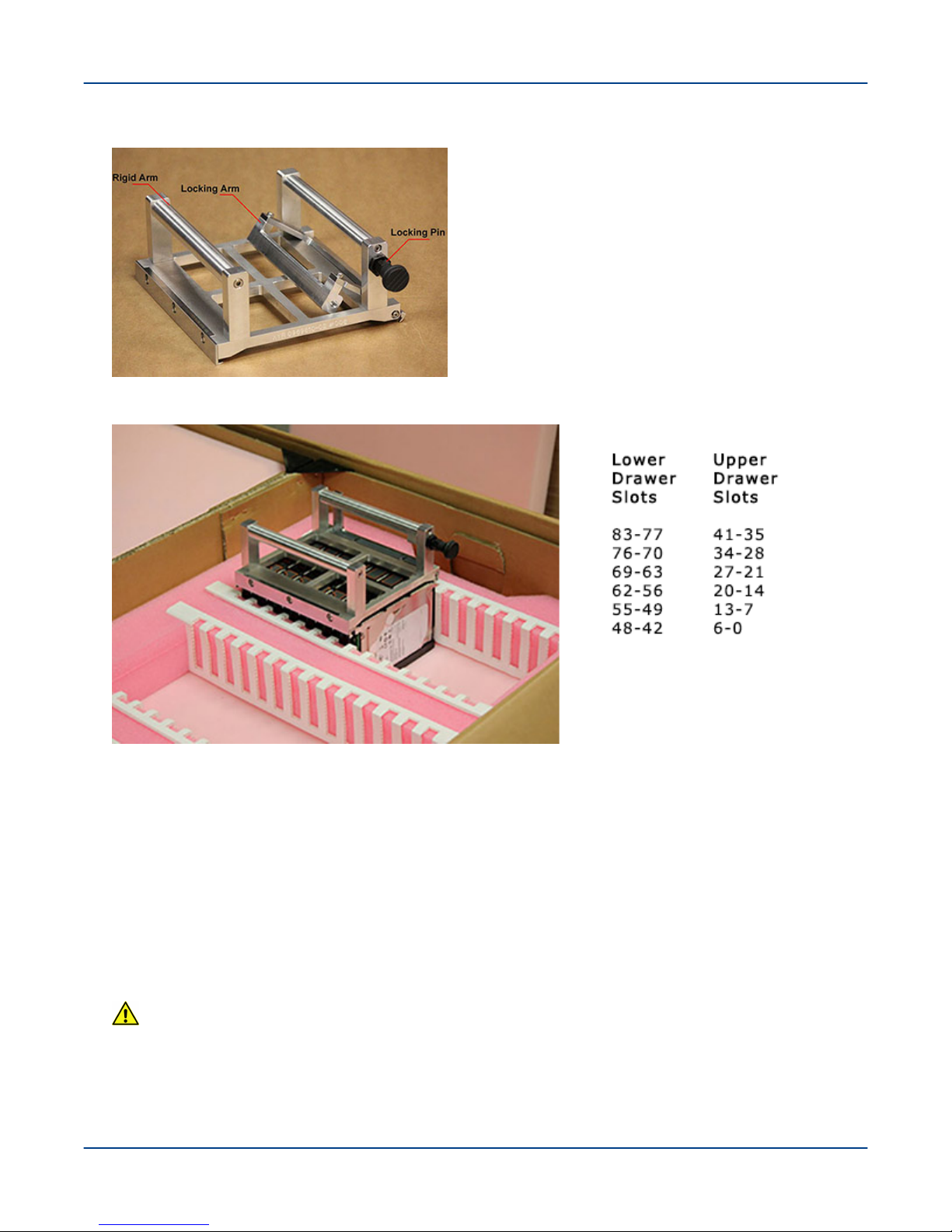
Figure 10. Speedloader
Figure 11. Speedloader Drive Slot Insertion Order
Install Disk Drives in a 5U84 Enclosure
16. Pull out on the locking pin to release the locking arm side.
17. Position the rigid side of the speedloader to one side of the drives (at a slight angle), rotate the speedloader
into position on the other side of the drives, and close the locking arm.
18. Verify that the drives are aligned between the fingers on the underside of the speedloader
IMPORTANT: Do not force the locking arm to close. If necessary, apply slight pressure to the drive(s)
to align them, and then close the locking arm.
19. Carefully lift the disks clear of the packaging, and position them into the slots at the correct location.
(See table for correct drive slot locations.)
CAUTION: The speedloader with drives weighs up to 17.6 lbs (8 kg). Handle with care to avoid the
risk of back injury.
20. Pull the locking pin to release the locking arm, and remove the speedloader from the drives.
23

Install Disk Drives in a 5U84 Enclosure
21. Lock the drives into the slot: press down while sliding the latch to the locked position, towards the rear of the
enclosure. Repeat for each disk drive.
22. Note the position of the interface card, as the drives must be installed with the card facing the front of the
drawer.
23. Press the button on each drawer slide to release the drawer, then slide the drawer back into the enclosure.
24. Repeat the steps until both the drawers have been fully populated with either disk drives or dummy carriers.
25. Close the second drawer and secure the two drawer latches with a T-20 Torx screwdriver.
26. If During Initial Rack Installation: Until the rack is in its final position, repeat for the second enclosure only,
working from the lower drawer upwards.
Install the disk drives in only the two lowest 5U84 (SSU) enclosures, until the rack is in its final position.
27. If the Rack Is in its Final Position: After the rack is located in its final position, continue populating all the
drives for the configuration, working from the lowest empty drawer up.
IMPORTANT: Any drive bay not occupied by a populated drive carrier must have a dummy drive
carrier installed for proper airflow.
24

Install Disk Drives in a 2U24 Enclosure
7
Install Disk Drives in a 2U24 Enclosure
Prerequisites
● A disk drive has failed and has been removed from the 2U24 enclosure
● A T10 Torx screwdriver may be required to unlock the drive carrier
About this task
Disk drives in the 2U24 enclosure are installed at the factory and do not need to be installed during a
system installation. This procedure is for reference only.
CAUTION:
● EQUIPMENT OVERHEATING
● All drive slots must have a disk drive carrier module or a dummy carrier module installed to maintain a
balanced airflow.
CAUTION:
● EQUIPMENT DAMAGE
● Observe ESD precautions when handling this equipment. Failure to do so can result in equipment
damage.
Procedure
1. If the disk drives are already installed in the 2U24 enclosure, skip this procedure.
2. Remove the disk drive in its drive carrier from its anti-static protective package.
3. Verify that the drive carrier handle is released and in the open position.
A T10 Torx screwdriver may be required to unlock the drive carrier.
4. Insert the drive carrier module into the desired empty drive slot in the enclosure.
Drive slots are numbered 0 through 23, from left to right.
25
Install Disk Drives in a 2U24 Enclosure
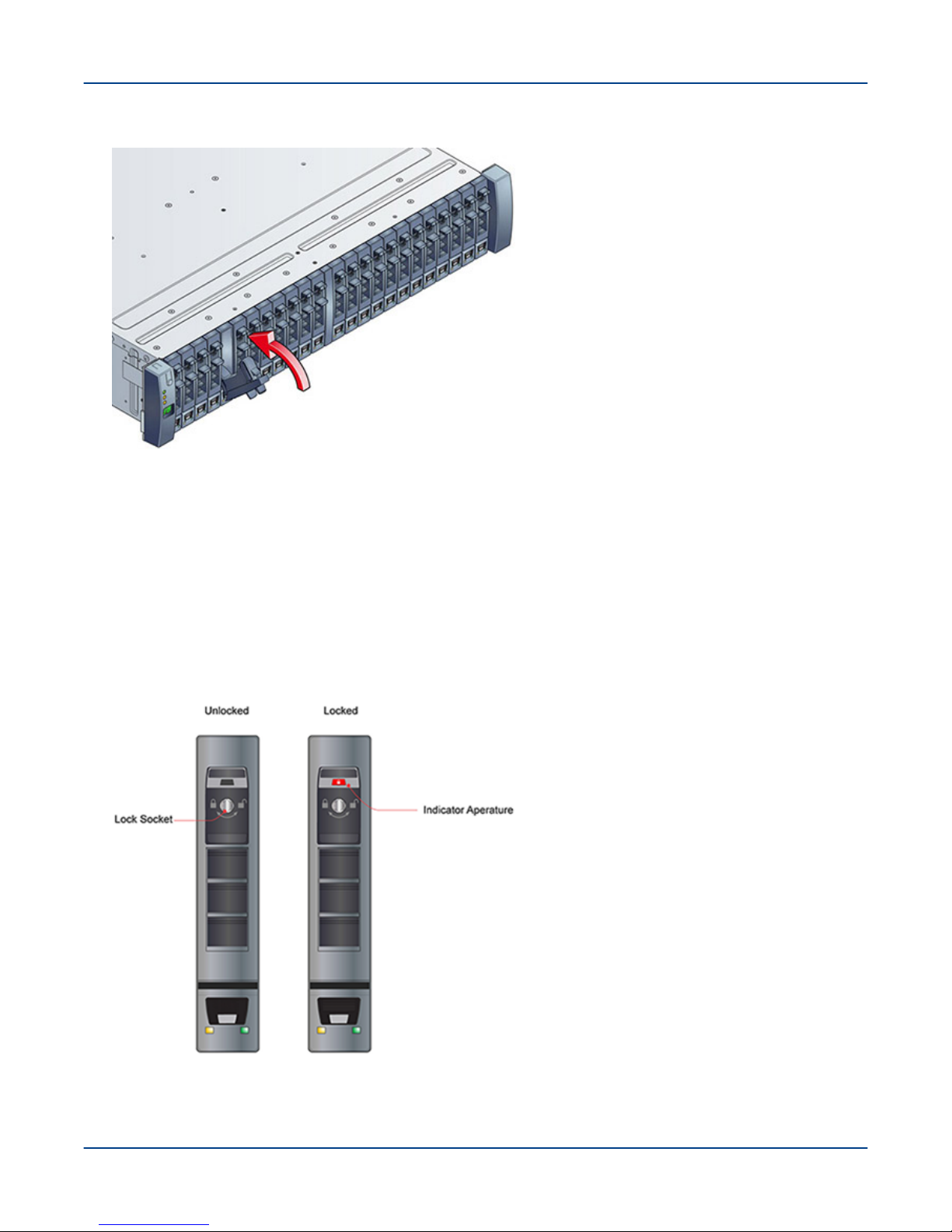
Figure 12. Secure the Drive Carrier
5. Seat the drive carrier by pressing fingers on the handle latch, pivoting it to a closed position, as shown.
The latch clicks as it engages and holds the handle closed.
6. Continue populating all the drives for the configuration.
IMPORTANT: Any drive bay not occupied by a populated drive carrier must have a dummy drive
carrier installed, to ensure proper air circulation.
7. Engage the drive carrier locks, using a T10 Torx screwdriver, and rotating clockwise until the red indicator
appears in the aperture above the key, as shown.
Figure 13. Drive Carrier Unlocked and Locked
26

Cable the External Power Connections
8
Cable the External Power Connections
Prerequisites
All ClusterStor L300 and L300N system racks have been positioned in their permanent locations.
About this task
All internal cable connections in the ClusterStor L300 and L300N system are made at the factory when the
components are installed in the rack. Only a few external cable connections are needed when the system is
installed at the customer site. This section covers primarily facility power and power cord connections.
See Cable Inter-rack Local Management Network (LMN) on page 36 for the cabling steps and diagrams for
connecting the system into the customer environment.
IMPORTANT: Power connections within a ClusterStor L300 and L300N system should be considered
carefully, as the loads are large. Where possible, balance the load equally across all 3 phases.
WARNING:
● Serious Injury or Equipment Damage
● Always perform a ground (earth) continuity and insulation test after completing the hardware
installation and prior to powering on the system.
NOTE: Depending on the installation, each PDU power cord may be routed out of the top of the rack
cabinet, or out of the bottom into the sub-floor system, and then connected to the appropriate facility
power connection.
The PDUs must be inverted to feed the power through the top of the ClusterStor L300 and L300N rack. Note that
the power sockets are always numbered from the top down; therefore, although the numbering may visually seem
incorrect, the power sockets do have the correct number assignments.
27
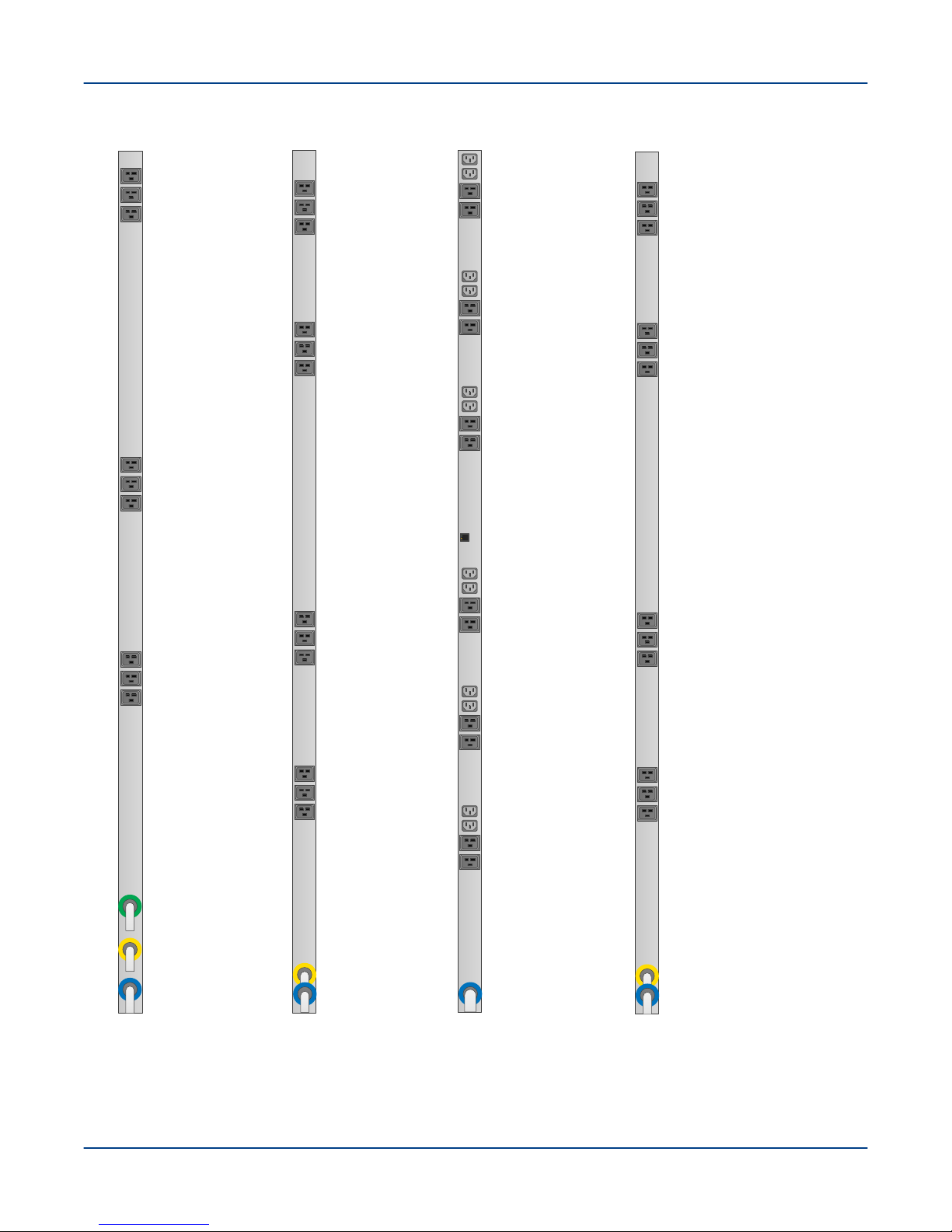
Figure 14. ClusterStor L300 and L300N PDU Options, Bottom Feed
32A 415V
EMEA
PX2-5104X2-V2
50A 208V
US
PX2-5100X2-V2
C19 (A1)
C19 (A2)
C19 (A3)
C19 (B4)
C19 (B5)
C19 (B6)
C19 (A7)
C19 (A8)
C19 (A9)
C19 (B10)
C19 (B11)
C19 (B12)
Line A
Line B
C19 (A1)
C19 (A2)
C19 (A3)
C19 (B4)
C19 (B5)
C19 (B6)
C19 (A7)
C19 (A8)
C19 (A9)
C19 (B10)
C19 (B11)
C19 (B12)
Line A
Line B
PX2-5965X3-V2
24A 208V
US
C19 (A1)
C19 (A2)
C19 (A3)
C19 (B4)
C19 (B5)
C19 (B6)
C19 (C7)
C19 (C8)
C19 (C9)
Line A
Line B
Line C
60A 208V
US
PX2-5551-N4V2
Line A
C13 (A1)
C13 (A2)
C19 (A3)
C19 (A4)
C13 (A5)
C13 (A6)
C19 (A7)
C19 (A8)
C13 (A9)
C13 (A10)
C19 (A11)
C19 (A12)
C13 (A13)
C13 (A14)
C19 (A15)
C19 (A16)
C13 (A17)
C13 (A18)
C19 (A19)
C19 (A20)
C13 (A21)
C13 (A22)
C19 (A23)
C19 (A24)
Cable the External Power Connections
28
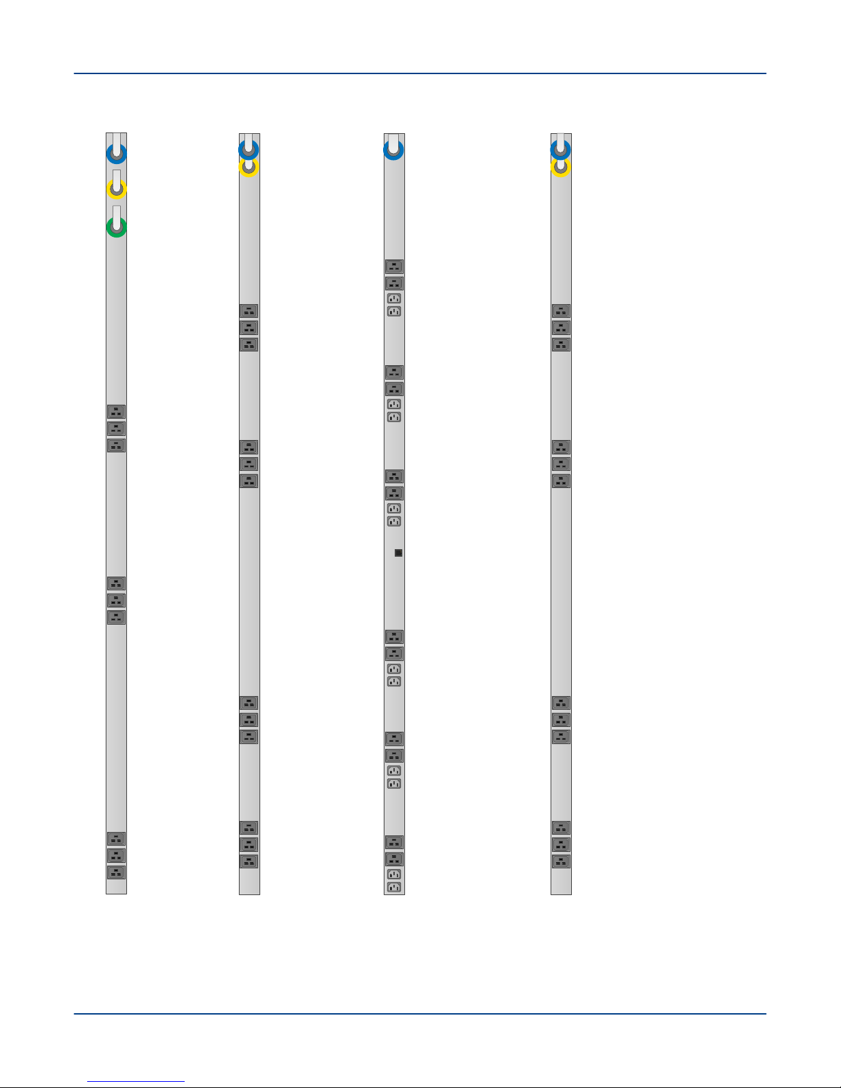
Figure 15. ClusterStor L300 and L300N PDU Options, Top Feed
50A 208V
US
PX2-5100X2-V2
C19 (A1)
C19 (A2)
C19 (A3)
C19 (B4)
C19 (B5)
C19 (B6)
C19 (A7)
C19 (A8)
C19 (A9)
C19 (B10)
C19 (B11)
C19 (B12)
Line A
Line B
32A 415V
EMEA
PX2-5104X2-V2
C19 (A1)
C19 (A2)
C19 (A3)
C19 (B4)
C19 (B5)
C19 (B6)
C19 (A7)
C19 (A8)
C19 (A9)
C19 (B10)
C19 (B11)
C19 (B12)
Line A
Line B
PX2-5965X3-V2
24A 208V
US
C19 (A1)
C19 (A2)
C19 (A3)
C19 (B4)
C19 (B5)
C19 (B6)
C19 (C7)
C19 (C8)
C19 (C9)
Line A
Line B
Line C
60A 208V
US
PX2-5551-N4V
Line A
C13 (A1)
C13 (A2)
C19 (A3)
C19 (A4)
C13 (A5)
C13 (A6)
C19 (A7)
C19 (A8)
C13 (A9)
C13 (A10)
C19 (A11)
C19 (A12)
C13 (A13)
C13 (A14)
C19 (A15)
C19 (A16)
C13 (A17)
C13 (A18)
C19 (A19)
C19 (A20)
C13 (A21)
C13 (A22)
C19 (A23)
C19 (A24)
Cable the External Power Connections
29
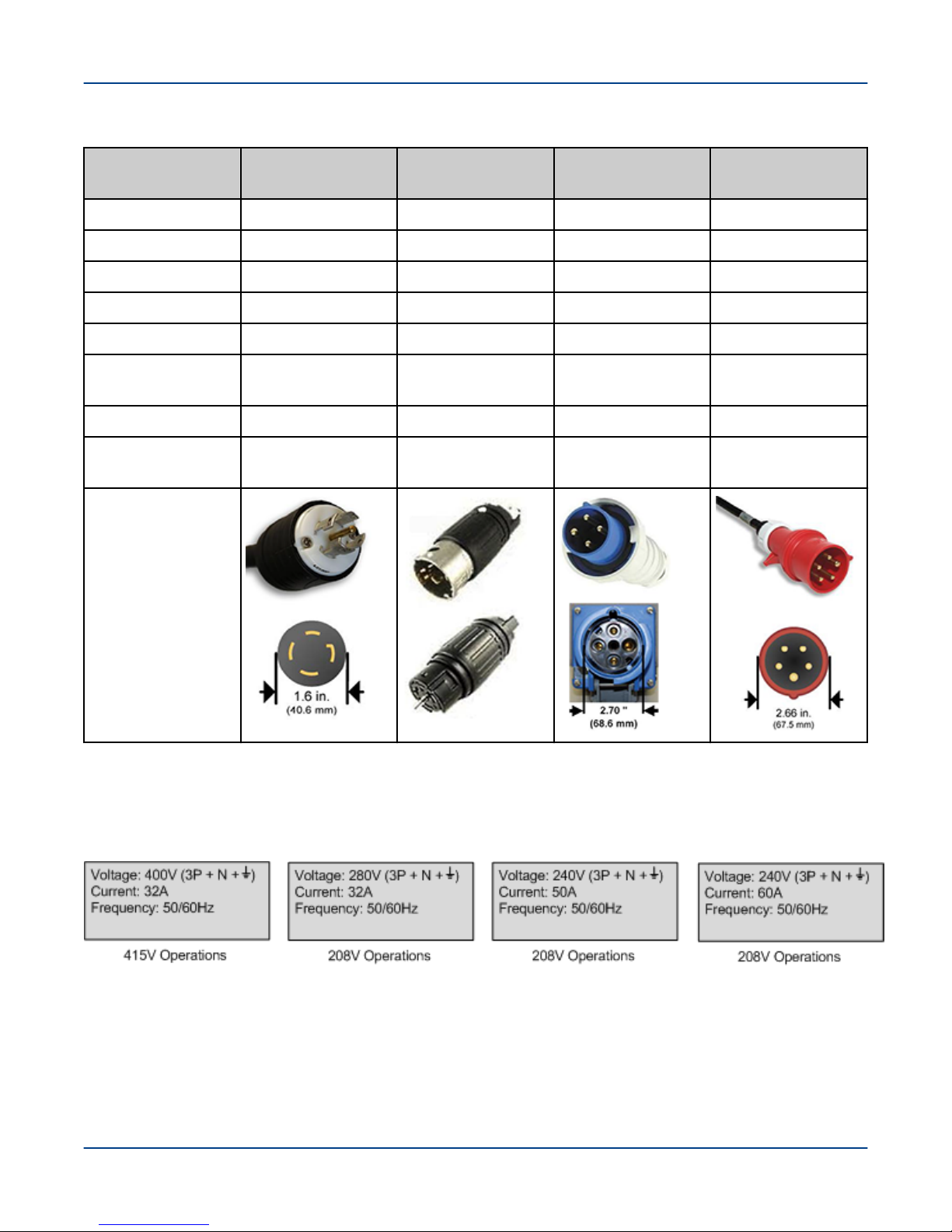
Table 3. ClusterStor L300 and L300N PDU Specifications
Cable the External Power Connections
Operation PX2-5965X3-V2
208V
Plug Type NEMA L21-30P Hubbell CS8365C IEC60309 60A 3P IEC60309 32A 3PY
Input Phase 190-208 3Φ-Delta 208-240V 3Φ-Delta 208-240V 3Φ-Delta 380-415 3Φ Wye
Output 190-208V 208-240V 208-240V 220-240V
Outlet Type C19 C19 C19 C19
Form Factor 0U 0U 0U 0U
Circuit Breaker
(QTY)
Rated Current 24A/Phase 40A/Phase 48A/Phase 32A/Phase
Power Capacity 23.7kVA at 190V,
Image
20A, 2-pole UL489
(9)
25.9kVA at 208V
PX2-5100X2-V2
208V
20A, 2-pole UL489
(12)
28.8kVA @ 208V,
33.3kVA at 240V
PX2-5551-N4V2
208V
20A, 2-pole
LEGBX66- 20 (6)
17.3kVA at 208V,
20.0kVA at 240V
PX2-5104X2-V2
415V
16A, 1-pole UL489,
VDE (12)
42.2kVA at 380V,
46.0kVA at 415V
NOTE: The rating labels shown in the preceding table provide the 20% de-rated factor values as required
for operations in the USA.
Figure 16. Rating Labels
Procedure
1. Place the rack PDU power switches and the power switches on all the other components in the OFF position.
Not all ClusterStor L300 and L300N components have power switches; in those cases the power cord
controls power to the component. Verify that the power cords for those components are disconnected.
30
 Loading...