

Page 1
c:
RESEARCH
Any
shipment
United States requires a U.S. Government
export
license.
to a country
INC.
J
outside
of
the
CRAY COMPUTER SYSTEMS
CRAY X-MP SERIES
MODELS
MAINFRAME REFERENCE
HR-0032
Copyright© 1982, 1984
or
parts thereof may
permission of CRAY
by
CRAY RESEARCH, INC. This manual
not
RESEARCH, INC.
22 & 24
MANUAL
be reproduced in any form without
Page 2
RECORD OF REVISION
E
i
~ESEA~CHJ
INC.
PUBLICATION
NUMBER
HR-0032
Each time
incorporated into
against
Ol
Every
corner.
the
one
Requests for copies
CRAY RESEARCH,
1440
Mendota Heights, Minnesota
thil
manuel il revised and reprinted, all
the
the
current
for
the
first change packet
P9
changed
Changes
page number indicates
page
to
another,
Northland Drive,
Revision
new version and
version in
by
to
part
but
of
INC.,
Description
a reprint
of 8 P8SlI
that
has
Crav Research, Inc. publications and comments
November, 1982 -
A
July,
for
hardware
functions.
Second
functional
technical
made.
chan~
the
the
form of ch.ange peckets. Each change packet
of
each revillon level.
or
the
not
otherwise
55120
new version IS
by
a change packet has
are noted
entire page is new; a
bY
a change bar along
changed.
Original
1984 -
Reprint
performance
Information
Vector
This
Logical
unit
and
editorial
revision
is
issued against
..
Igned an alphabetic level. Between reprints, changes may be issued
the
revision level
dot
the
in
ttle same place indicates
printing.
with
revision.
monitoring
was
also
functional
not
available
changes
obsoletes
the
previous version in
is
assigned 8 numeric designator, starting with
and
margin
about
change packet number in
of
the
page. A change bar in
these publications should
Instructions
and
added
unit
on
and
all
to
is
all
correccions
previous
the
form
of
change packets are
the
lower righthand
the
be
directed to:
margin opposite
that
information has been moved from
were added
SECDED
explain
used
systems.
maintenance
how
the
although
this
Numerous
were
also
printings.
BR-0032
ii
A
Page 3
PREFACE
This
dual-processor
assist
computers.
The
equipment.
Units
hardware
computer
Details
Storage
publication
programmers
manual
HR-0030
HR-0630
HR-003l
describes
that
execute
exceptions,
systems.
of
the
Device
///////////////////////////////////////////////////////
This
frequency
accordance
interference
tested
A
computing
FCC
protection
commercial
a
residential
which
to
the
describes
computer
and
It
also
describes
instructions,
I/O
Subsystem,
are
given
I/O
Subsystem
Mass
Rules,
take
interference.
Storage
Solid-state
equipment
energy
with
and
found
which
against
environment.
case
the
whatever
systems,
engineers
the
overall
and
provide
in
Storage
generates,
and
the
to
radio
to
device
are
area
user
measures
the
functions
models
and
computer
the
operation
provide
interprocessor
the
disk
the
following
Hardware
Subsystem
Device
WARNING
uses,
if
not
instructions
communications.
comply
pursuant
designed
such
is
at
with
interference
Operation
likely
his
own
may
of
CRAY
22
and
assumes a familiarity
system,
of
memory
storage
publications:
Reference
Hardware
(SSO@)
and
installed
manual,
the
to
Subpart J of
to
provide
of
to
cause
expense
be
required
X-MP
Series
24.
the
units,
Manual
Reference
can
and
limits
when
this
It
its
configurations,
Central
protection,
communications
and
Reference
radiate
used
may
cause
It
has
for a Class
Part
reasonable
operated
equipment
interference
will
be
to
correct
is
been
written
with
Processing
report
the
Manual
Manual
radio
in
15
of
in
in
required
to
digital
and
within
Solid-state
a
in
the
HR-0032
///////////////////////////////////////////////////////
iii
A
Page 4

Page 5
CONTENTS,
PREFACE
1.
SYSTEM
INTRODUCTION
CONVENTIONS
SYSTEM
SYSTEM
2.
CPU
SHARED
DESCRIPTION
•
Italics
Register
Number
Clock
•
conventions
conventions
per
iod
COMPONENTS
Central
Processing
Interfaces
I/O
Subsystem
Disk
Solid-state
Condensing
Power
storage
Storage
units
distribution
Motor-generator
CONFIGURATION
RESOURCES
•
•
units.
units
•
•
Units
Device
units
•
iii
1-1
1-1
1-4
1-4
1-4
1-4
1-4
1-5
1-5
1-7
1-9
1-11
1-12
1-13
1-14
1-15
1-16
2-1
INTRODUCTION
CENTRAL
MEMORY
Memory
Memory
Memory
16-bank
Memory
INTER-CPU
Real-time
Inter-CPU
•
•
organization
addressing
Memory
Memory
access
Conflict
addressing
addressing
•
•
resolution
Bank Busy
Simultaneous
Section
Memory
access
phasing
error
COMMUNICATION
clock
Access
priorities
•
correction
SECTION
•
communication
Shared
Semaphore
Address
registers
•
for
for
conflict
Bank
conflict
•
and
and
Shared
HR-0032 v
6-co1umn
12-co1umn
conflict
•
•
control
Scalar
mainframe
mainframe
•
registers
2-1
2-1
2-2
2-3
•
2-3
2-4
2-4
2-7
2-7
2-7
2-7
2-7
2-8
2-8
2-10
2-10
2-11
•
2-12
2-12
A
Page 6
2.
CPU
SHARED
CPU
INPUT/OUTPUT
Data
Data
6 Mbyte
Multi-CPU programming • • • • • •
6 Mbyte
Input
Input
Output
Programmed
Memory
I/O
Memory
I/O
I/O
I/O
RESOURCES
transfer
transfer
per
per
channel
channel
channel
master
access
lockout
bank
memory
memory
memory
conflicts
addressing
(continued)
SECTION
for
for
second
second
programming • • • • • •
error
programming
• • • • •
• • • • • • • • • •
conflicts
• • • • • • • • • • • • • •
Solid-state
I/O
Subsystem
channels
channel
conditions
clear
to
Storage
• • • • • •
• • • • •
operation
••••••
••••
external
. . . . . . .
• • •
. .
request
conditions
• • • • •
•
Device
~
••••
device
•
. . . . . .
. . . . .
. . . .
· . . . .
. . .
· . .
· . . . . .
· .
· .
· . .
2-14
2-15
2-16
2-16
2-17
2-18
2-19
2-20
2-20
2-21
2-21
2-24
2-24
2-24
2-25
2-25
CPU
3.
CONTROL
INTRODUCTION
INSTRUCTION
EXCHANGE
Active
Exchange
Exchange Package management • •
SECTION
• • • • • • • • •
ISSUE
Program
Next
Current
Lower
Instruction
Exchange
Exchange
Address
Instruction
Instruction
Instruction
MECHANISM
Processor
vector
Enable
Memory
Exchange
Mode
Flag
Cluster
Program
A
registers
S
registers
Program
Memory
Exchange Package • • • •
Exchange
Exchange
Exchange
Exchange
AND
buffers
• • • • • • • • •
package
number
not
used
second
error
registers
Address
register
register
Number
State
Address
field
sequence
initiated
initiated
initiated
sequence
. . . . . . . . . . . . . . . . . . . . . .
· . . .
CONTROL
register
Parcel
Parcel
Parcel
(VNU)
vector
data
register
register
register
.,
.
logical
••••
. .
•
(ESVL)
· .
· . .
. . . .
. .
· . .
. .
register
••••••
••••••
register
register
••
• • •
•••••
register
registers
• • • • • • •
by
deadstart
by
Interrupt
by
program
issue
. .
•
sequence
flag
exit
conditions
· .
· .
· . .
set
• •
· . .
. . . .
•
•
.
. .
3-1
3-1
3-1
3-2
3-2
3-2
3-3
3-3
3-5
3-5
3-7
3-7
3-8
3-8
3-9
3-9
3-9
3-11
3-12
3-12
3-12
3-12
3-13
3-13
3-13
3-13
3-14
3-14
3-14
3-15
3-15
HR-0032
vi
A
Page 7
3.
CPU
CONTROL
SECTION
(continued)
MEMORY
Instruction
Instruction
Data
Data
Program
Operand
PROGRAMMABLE
Instructions
Interrupt
Interrupt
Clear
PERFOBMANCE
DEADSTART
4.
CPU
COMPUTATION
INTRODUCTION
OPERATING
ADDRESS
A
B
SCALAR
S
T
VECTOR
V
Vector
FUNCTIONAL
Address
Scalar
Vector
FIELD
registers
registers
REGISTERS
registers
registers
REGISTERS
registers
PROTECTION
Base
Address
Limit
range
range
CLOCK
Interval
Countdown
programmable
MONITOR
SEQUENCE
•
REGISTERS
REGISTERS
V
register
control
Vector
Vector
UNITS
functional
Address
Address
functional
Scalar
Scalar
Scalar
Scalar
functional
functional
Vector
Vector
Vector
Full
Vector
Second
Vector
. . . . .
Base
Address
SECTION
Length
Mask
Add
Shift
Logical
Population/Parity/Leading
functional
Add
Shift
Vector
Population/parity
Address
Limit
•
•
• • • • • •
Add
Multiply
Address
register
register
error
error
•
• • • • •
registers
•
• •
register
counter
clock
reservations
register
register
units
functional
units
functional
functional
functional
unit
units
functional
functional
Logical
Logical
register
register
•
•
•
interrupt
and
•
•
unit
functional
•
unit
unit
•
unit
reservation
unit
unit
functional
functional
unit
functional
•
request
chaining
unit
•
•
•
•
unit
• •
Zero
•
unit
unit
3-16
3-17
3-17
.
.
•
3-18
3-18
3-18
3-19
3-19
3-19
3-19
3-20
3-20
3-20
3-21
4-1
4-1
4-3
4-3
4-3
4-5
4-6
4-6
4-8
4-9
4-9
4-12
4-13
4-13
4-13
4-14
4-14
4-15
4-15
4-15
4-15
4-16
4-16
4-16
4-16
4-17
4-17
4-17
4-18
4-18
4-19
HR-0032
vii
A
Page 8

FONC'lIONAL
UNITS
(continued)
ARITHMETIC
LOGICAL
CPU
5.
INSTRUCTION
SPECIAL
INSTRUCTION
INSTRUCTION
Floating-point
Floating-point
Floating-point
Reciprocal
OPERATIONS
Integer
Floating-point
OPERATIONS
INSTRUCTIONS
I-parcel
and k
I-parcel
and k
2-parcel
and m
2-parcel
and m
REGISTER
arithmetic
Normalized
Floating-point
Floating-point
Floating-point
Floating-point
functional
Double-precision
Addition
Multiplication
Division
Newton's
Derivation
FORMAT
instruction
fields
instruction
fields
instruction
fields
instruction
fields
ISSUE
DESCRIPTIONS
functional
Add
Multiply
Approximation
• • • • • • • • • • • • • • • • •
•••••••••••
arithmetic
floating-point
range
algorithm
algorithm
algorithm
method
of
the
• • • • • • • • •
. . . .
••
•
format
••
• • • • • • • • • • • • • • • •
format
•••
• • • • • • • • • • • • • • • • •
VALUES
• • •
• • • • • • • • • • •
format
format
• • • • • • • • •
• •
units
functional
• • • • • • • • • • •
errors
Add
Multiply
Reciprocal
unit
• • • • • • • • • • •
numbers • • • • • • • • • •
• • • • • • • • • • • • •
• • •
•••
division
• • • •
unit
functional
functional
numbers
functional
functional
Approximation
• • • •
algorithm
••
unit
unit
•••••
• • •
unit
. . . . . . . .
. . . .
with
discrete
with
with
with
combined j
combined
combined
• • • •
• • • • •
•
unit
• •
. .
j
j,
k,
i,
j,
· . .
· . .
• • • • •
• • •
· .
· . .
· .
k,
. .
. .
. . .
4-20
4-20
4-20
4-21
4-21
4-21
4-22
4-23
4-24
4-24
4-25
4-27
4-27
4-27
4-28
4-30
4-30
4-31
4-35
5-1
5-1
5-1
5-2
5-2
5-3
5-4
5-5
5-6
APPENDIX
A.
INSTRUCTION
B. 6
HR-0032
MBYTE
INTRODUCTION
6
MBYTE
SECTION
PER
PER
Data
parity
bits
SUMMARY
SEOOND
• • • • • • • • • •
SEOOND
bits 0 through
FOR
CHANNEL
INPUT
20 through
CRAY
DESCRIPTIONS
CHANNEL
15
2
3 • • • • • • • • • • •
X-MP
MODELS
22
AND
. . . . .
SIGNAL
• • • • • • • • • •
viii
SEQUENCE.
24 • • • • • • •
. . . . . .
. . .
. . . .
. .
A-I
B-1
B-1
8-1
B-1
B-2
A
Page 9
6
MBYTE
6
MBYTE
C.
PERFORMANCE
PER
SEOOND
Ready
Resume
Disconnect
Data
Parity
Ready
Resume
Disconnect
signal
signal
PER
SECOND
bits
bits 0 through
signal
signal
MONITOR
INPUT
signal
20 through
signal
• • • • • • • • • •
OUTPUT
• • • •
. . . . . . . . . . . . . . . . . . . . . .
CHANNEL
• • • • • • • • • • • • • • •
• • • • • • • • • • • • • • • •
CHANNEL
15
2
3 •
• • • •
• • • • •
SIGNAL
SIGNAL
••
SEQUENCE
• • • • • • • •
SEQUENCE
(continued)
. . .
. .
. .
B-3
B-3
B-3
B-3
B-4
B-5
B-5
B-5
B-5
C-l
INTRODUCTION
SELECTING
READING
TESTING
D.
SECDED
INTRODUCTION
VERIFICATION
VERIFICATION
VERIFICATION
CLEARING
FIGURES
1-1
1-2
1-3
1-4
1-5
1-6
1-7
1-8
1-9
1-10
1-11
1-12
1-13
2-1
2-2
2-3
2-4
CRAY
Cray
Basic
Control
CRAY
TYPical
I/O
DD-29
Solid-state
Condensing
Power
Motor-generator
Block
with
Block
with
Central
6-column
6-column
12-co1umn memory
• • • • • • • • •
PERFORMANCE
PERFORMANCE
PERFORMANCE
MAINTENANCE
• • • • • • • • • • • • •
OF
CHECK
OF
CHECK
OF
ERROR
MAINTENANCE
X-MP
Model 22
I/O
Subsystem
organization
and
data
X-MP
Models 22
interface
Subsystem
Disk
distribution
diagram
full
diagram
block
Memory
memory
memory
chassis
Storage
Storage
unit
of
disk
capacity
of
multiplexer
organization
EVENTS
RESULTS
COUNTERS •
FUNCTIONS
BIT
BIT
DETECTION
MODE
or
24
and
an
of
the
paths
cabinet
••••••••••
equipment
CRAY
CRAY
address
address
address
for a single
or
24
•••
Unit
Device
units
X-MP
X~
channels
. . . . . . . . . . .
. . . . . . . . . . . . .
. . . . . . . . . . . . . . . . . .
STORAGE
GENERATION
AND
FUNCTIONS
l2-column
SSD
dual-processor
6-column
• • • • • • •
chassis
• • • • • • • • •
dual-processor
•••••••••
dual-processor
for a dual-processor
(32
banks)
(16
banks)
(32
banks)
•
CORRECTION
••••••
mainframe
••••••
CPU
mainframe
• • • •
• • • •
• • • • • • • • • • • • • •
• • •
• • •
•••••
• •
• • • •
•••
•
with
• • • • • • • •
system
chassis
system
• • • • • • • • • •
system
• • • • • • •
a
system
. . .
• • • • •
. . .
C-1
C-l
C-3
C-3
D-l
D-l
D-1
D-2
D-2
D-3
1-2
1-5
1-6
1-7
1-8
1-10
1-11
1-12
1-13
1-14
1-15
1-16
1-17
2-2
2-3
2-3
2-4
HR-0032
ix
A
Page 10
FIGURES
(continued)
2-5
2-6
2-7
2-8
2-9
2-10
2-11
3-1
3-2
3-3
4-1
4-2
4-3
4-4
4-5
4-6
4-7
4-8
4-9
4-10
5-1
5-2
5-3
5-4
5-5
5-6
5-7
5-8
5-9
5-10
5-11
5-12
l2-column
Memory
Error
Shared
Basic
Channel
memory
data
correction
registers
I/O
program
I/O
Input/output
Instruction
Instruction
Exchange
Address
Scalar
vector
Integer
package
registers
registers
registers
data
Floating-point
Exponent
Integer
functional
49-bit
matrix
multiply
unit
floating-point
Floating-point
Newton's
General
I-parcel
I-parcel
k
fields
2-parcel
m
fields
2-parcel
combined
2-parcel
with
vector
vector
vector
vector
vector
VL
greater
vector
method
form
instruction
instruction
• • • • • • • • • • • • • • • • • • • • • • • • • • •
instruction
• • • • • • • • • • • • • • • • • • • • • • • • •
instruction
i,
instruction
combined
left
left
left
right
right
than
right
path
control
data
issue
buffers
formats
data
for
multiply
for
j,
k,
i,
double
double
double
double
double
1
double
address
with
matrix
and
flowchart
(shown
paths
and
(16
SECDED
real-time
for
••••••••
control
banks)
• • • • • • • • •
• • • • • • • • •
clock
•••••••••
one
elements
•••••••••••••
for a dual-processor
and
and
and
format
functional
functional
functional
• • • • •
• • • • • • • • • • • • • • • •
units
units
units
".
• • • •
Floating-point
in
Floating-point
••••
• • • • • • • • • • • •
addition
• • • • • • • • • •
partial-product
•••••••••••••••••••••••
instructions
format
format
format
format
and m
fields
format
j,
k,
and m fields
shift,
shift,
shift,
shift,
shift,
••••••
shift,
first
second
last
•••••••••••
with
with
with
discrete
combined j and
combined
for a branch
•••••••••
for a 24-bit
element,
element,
element
first
second
element
element,
• • • • • •
last
operation
• • • • • • • • • • •
• • • • • • • • •
processor)
• • • • • • • • • • • •
system
•
•
••••
••••
Multiply
unit
• • • • •
Multiply
sums
pyramid
j and k
j,
k, and
fields
with
immediate
constant
•••••••••••
VL
greater
VL
greater
than
• • • • • • • •
•
••••
• • • • • •
• •
. . .
• •
•
1 • •
than
2
2-4
2-8
2-9
2-11
2-19
2-22
2-23
3-1
3-3
3-6
4-4
4-7
4-10
4-22
4-23
4-25
4-27
4-28
4-29
4-31
5-1
5-2
5-2
5-3
5-4
5-4
5-71
5-71
5-71
5-72
5-73
5-73
TABLES
1-1
2-1
2-2
3-1
HR-0032
Access
Channel
CRAY
x~p
dual-processor
conflicts
in a dual-processor
word
assembly/disassembly
Exchange
Package
system
to
shared
computer
assignments
characteristics
registers
• • • •
• • • •
x A
1-3
2-13
2-18
3-7
Page 11
TABLES
(continued)
B-1
B-2
C-l
INDEX
Input
Output
channel
channel
Performance
signal
signal
counter
exchange
exchange
group
descriptions
• • • • • • • • • • •
• • • • • • • • • • • • • •
• • • • • •
B-2
B-4
C-2
HR-0032
xi
A
Page 12

Page 13
SYSTEM
INTRODUCTION
The
CRAY
X-MP/22
systems
can
scalar
systems'
that
achieve
and
vector
random-access,
contain
extremely
DESCRIPTION
and
CRAY
X-MP/24
two
central
high
processing
solid-state
multiprocessing
capabilities
are
powerful,
processing
memory
units
rates
of
(RAM)
both
general
(CPUs). The
by
CPUs
and
purpose
efficiently
combined
shared
computer
systems
using
with
registers.
1
the
the
Vector
ordered
two
greatly
processing.
providing
techniques.
Equipment
(see
2
are
matches
rates
devices,
In
Solid-state
provides
data
with a Cray
This
provides
processing
data.
or
more
exceeding
table
million
compatible
the
for
addition
files
section
solutions
options
communication
and a wide
significantly
overall
is
When
operations
the
Scalar
allow
1-1).
(model 22)
mainframe's
to
Storage
repetitively.
I/O
describes
Central
with
the
mainframe
Subsystem
system
the
performance
two
or
more
can
be
computational
operations
to
problems
the
systems
Memory
or 4 million
all
existing
processing
with
mass
variety
Device
system
of
and
can
improved
Figure
and
characteristics.
of
iterative
vector
executing
complement
not
of a dual-processor
models
storage
host
I/O
be
configured
throughput
1-1
an
SSD®.
components
operations
each
rates
readily
to
(model 24)
rates
computers.
Subsystem, a Cray
of
the
be
configured
of
the
with
units,
of
illustrates
and
operations
are
chained
9.5-nanosecond
conventional
vector
adaptable
64-bit
Cray
high
with
programs
configurations.
capability
to
for a particular
system
words.
I/O
input/output
other
the
peripheral
Research,
the
system.
that
mainframe
on
sets
together,
clock
scalar
by
vector
can
be
The
systems
Subsystem,
transfer
An
access
configured
Table
of
period,
use
either
which
Inc.,
SSD
large
1-1
HR-0032
1-1
A
Page 14
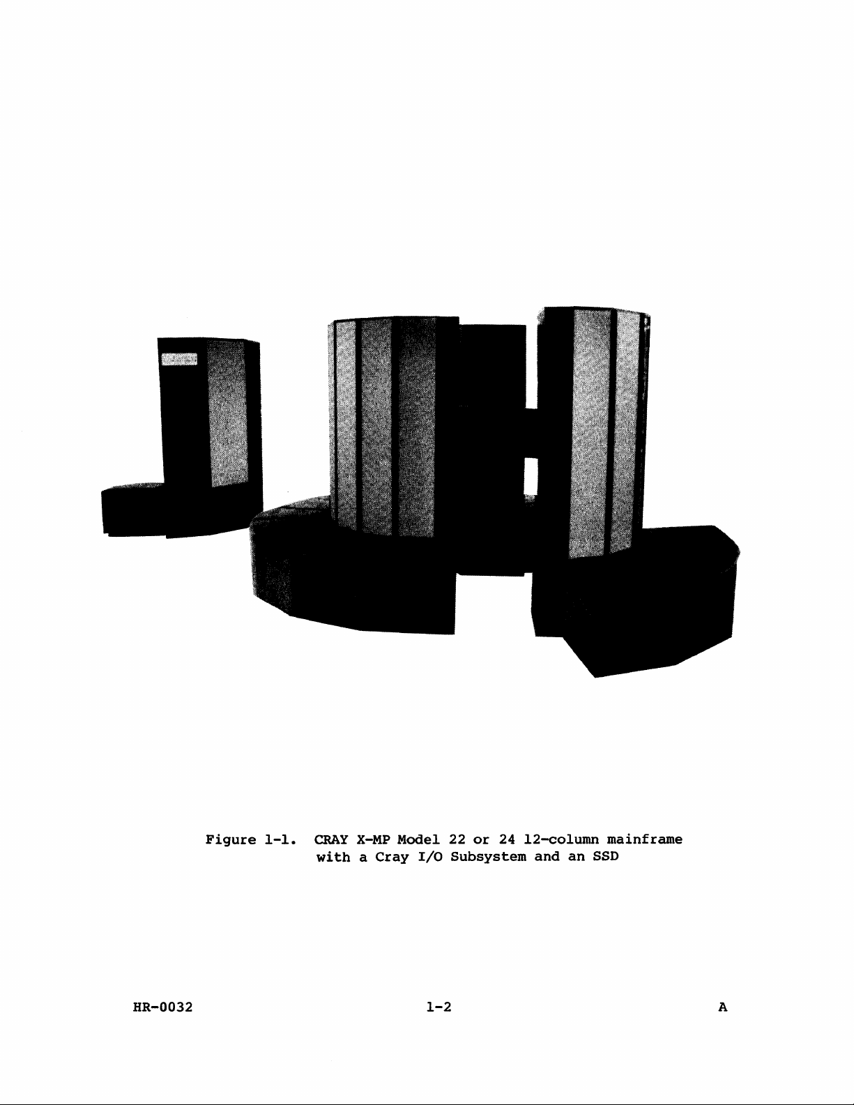
Figure
1-1.
CRAY
X-MP
Model 22
with a Cray
I/O
Subsystem
or
24
12-column
and
an
SSD
mainframe
HR-0032
1-2
A
Page 15
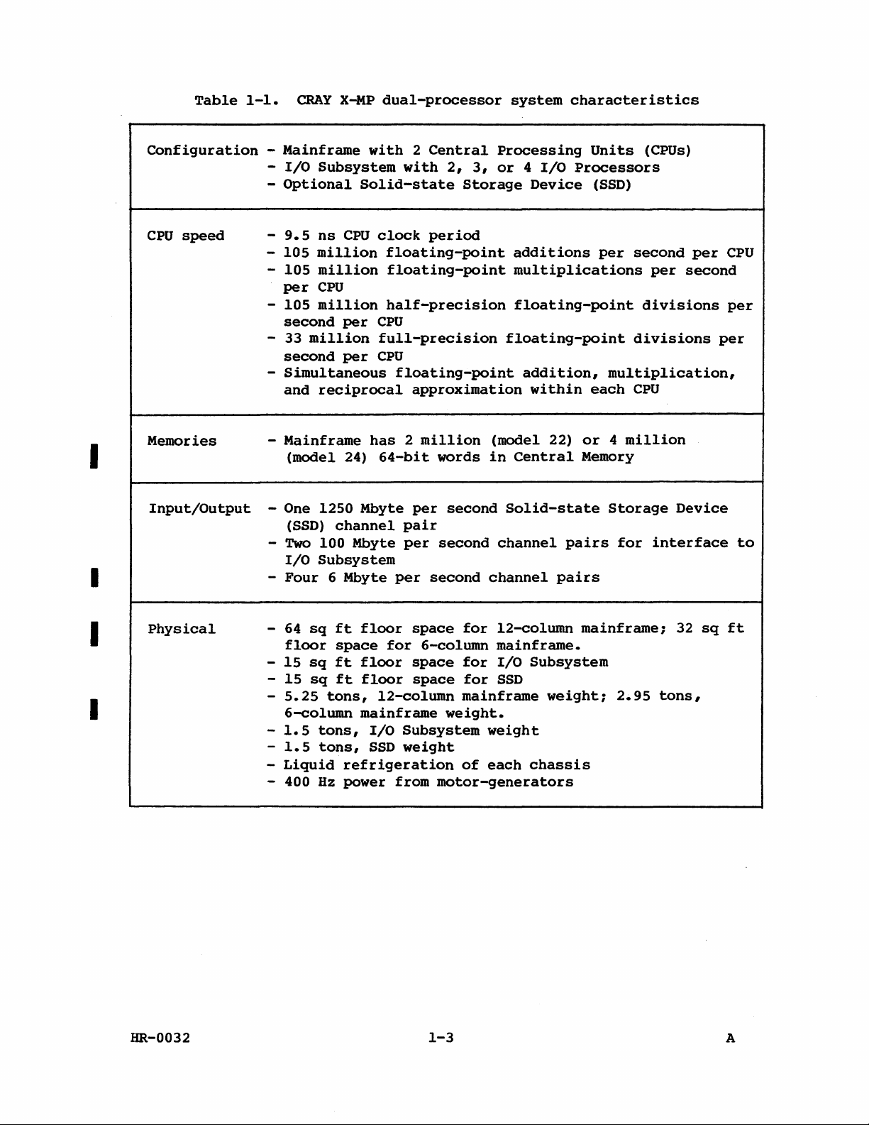
Table
1-1.
CRAY
X~
dual-processor
system
characteristics
I
I
Configuration
CPU
speed
Memories - Mainframe
Input/Output
- Mainframe
-
I/O
Subsystem
-
Optional
-
9.5
ns
CPU
-
105
million
-
105
million
per
CPU
-
105
million
second
- 33
second
-
Simultaneous
and
(model 24)
- One 1250 Mbyte
(SSD)
-
Two
I/O
-
Four
per
million
per
reciprocal
channel
100 Mbyte
Subsystem
6 Mbyte
with 2 Central
with
Solid-state
clock
floating-point
floating-point
half-precision
CPU
full-precision
CPU
floating-point
has 2 million
64-bit
pair
per
per
2,
period
approximation
words
per
second
second
second
Processing
3,
or 4 I/O
Storage
floating-point
(model 22)
in
Solid-state
channel
channel
Units
Processors
Device
additions
multiplications
floating-point
addition,
within
Central
(SSD)
per
multiplication,
each
or 4 million
Memory
Storage
pairs
pairs
(CPUs)
second
per
divisions
divisions
CPU
for
interface
per
second
Device
CPU
per
per
to
I
I
Physical
HR-0032
-
64
sq
floor
-
15
sq
-
15
sq
-
5.25
6-column
-
1.5
-
1.5
-
Liquid
- 400
ft
floor
space
ft
floor
ft
floor
tons,
mainframe
tons,
tons,
Hz
I/O
SSD
refrigeration
power from
space
for
6-column
space
space
l2-column
Subsystem
weight
motor-generators
1-3
for
l2-column
mainframe.
for
I/O
for
SSD
mainframe
weight.
weight
of
each
mainframe;
Subsystem
weight;
chassis
2.95
32
tons,
sq
ft
A
Page 16
CONVENTIONS
The
following
ITALICS
conventions
are
used
in
this
manual.
Italicized
REGISTER
CONVENTIONS
Parenthesized
of
shorthand
For
example,
contents
of
Designations
For
example,
the T register
specified
Register
2°.
Bit
by
bits
63
2
significant
most
significant
conventions
exceptions.
and
are
not
most
significant
register
register.
element
has
Bit
63.
lowercase
register
notation
"Branch
register
for
"Transmit
the
letters,
names
for
to
(P)"
P."
A, B,
(Tjk)
specified
the i designator."
are
numbered
of
an
S,
VL or T register
bit.
for
Bits
numbered
64
Bit
bit.
the
Exchange
in
and
bits,
63
2
corresponds
2~3
(A
the
as
powers
63
as
each
such
as
are
used
the
expression
means
S,
T,
to
by
the
right
of
an A or B register
"Branch
and V registers
sin
means
jk
designators
to
left
and B registers
Package
Exchange
Package
of 2 but
the
least
corresponding
to
element
jk,
indicate
frequently
"the
to
"Transmit
as
powers
value
represents
are
and
the
Vector
are
as
bits ° through
significant.
to
a word
0,
bit
variable
in
this
contents
the
address
are
used
the
to
the S register
of
value
24
bits.)
Mask
numbered
The
element
2°
corresponds
information.
manual
of
register
indicated
extensively.
contents
2,
starting
the
most
represents
The
numbering
register
from
Vector
left
63
with ° as
Mask
in a vector
as
of
the
to
to
a form
___
by
with
are
right
.ft
the
the
NUMBER
Unless
Octal
CONVENTIONS
otherwise
numbers
numbers,
instruction
CLOCK
The
PERIOD
basic
referred
and
other
HR-0032
are
channel
forms
unit
to
as a clock
timing
indicated,
indicated
numbers,
of
which
CPU
are
computation
period
considerations
numbers
with
an 8 subscript.
instruction
given
in
time
(CP).
are
in
this
parcels
octal
is
Instruction
often
1-4
manual
in
instruction
without
9.5
nanoseconds
issue,
measured
are
decimal
Exceptions
the
subscript.
(ns)
memory
in
CPs.
numbers.
are
register
buffers,
and
is
references,
and
A
Page 17

SYSTEM CDIPONEN'l'S
The
system
devices,
parts
can
for
of a system.
be
refrigeration,
distribution
components
CENTRAL PROCESSING UNITS
is
front-end
part
of
are
composed
interfaces,
the
system.
motor-generators
units
for
described
Optionally,
of
a mainframe and an
and
optional
a Cray
Supporting
to
the
mainframe,
on
the
following
I/O
tape
Solid-state
this
equipment
provide
I/O
Subsystem,
pages.
Subsystem.
devices
Storage
are
system
power, and power
and
Mass
are
also
Device
condensing
the
SSD.
storage
integral
(SSD)
units
System
Each
share
the
(CPO
CPU
has
Central
sections
basic
organization
components and
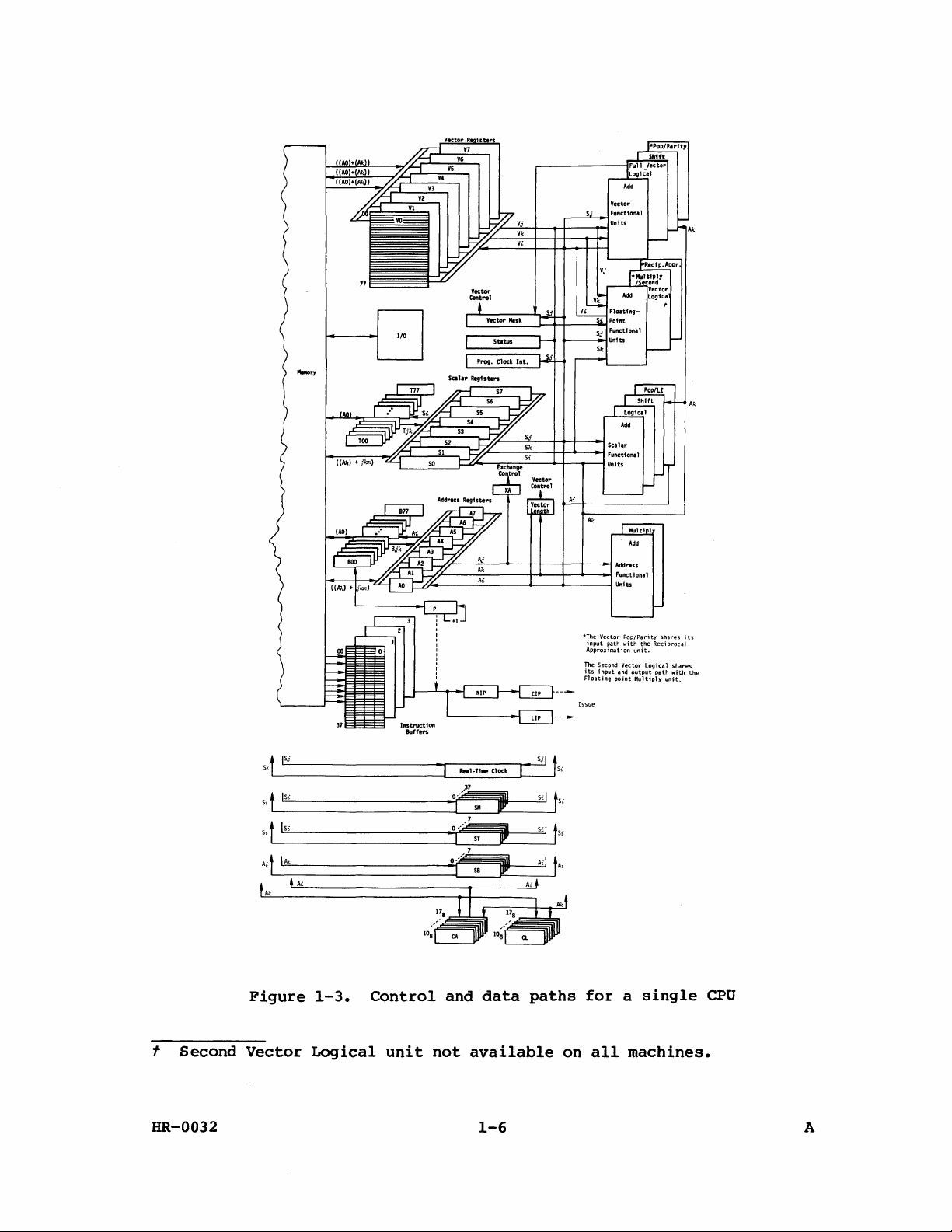
Figure
CONTROL
•
•
•
•
•
•
1-4
SECTION
Instruction
buffers
Control
registers
Exchange
mechanism
Interrupt
Programmable
clock
Status
register
shows mainframe
-
independent
Memory
are
and
described
of
control
COMPUTATION
•
•
and
SECTION
Registers
Functional
units
control
the
the
data
and
computation
inter-CPO communication and
in
later
computer,
paths
sections.)
figure
of a single
chassis.
CPU
COMMUNICATION
SECTION
Shared
2
million
•
Semaphore
•
registers
Real-time
•
register
MEMORY
64-bit
registers
SECTION
or 4 million
words
-
Clock
,
sections.
Figure
1-3
illustrates
CPU
COMPUTATION
SECTION
Registers
•
Functional
•
units
in
I/O
1-2
the
Both
CPOs
sections.
illustrates
the
system.
CONTROL
Instruction
•
buffers
Control
•
registers
Exchange
•
mechanism
Interrupt
•
Programmable
•
clock
Status
•
register
SECTION
I
HR-0032
Four
•
•
•
6 Mbyte
One 1250 Mbyte
Two
100 Mbyte
Figure
1-2.
I/O
SECTION
per
second
second
second
Basic
channel
channel
channel
organization
per
per
dual-processor
1-5
pairs
pair
pairs
of
system
the
A
Page 18
77
liD
Ak
jSj
Si
t
lSi
Si t
lSi
Si
t
IAi
Ait
AI:
Figure
Ai
1-3.
\....-,ij----.:..;.:.....----I-4--+-~_..j
c::..(.;'ooo----
lOa
Control
-I
___
ReaI-Ti.eClod
0--
I
0'-
I
and
A-'-i
____
SM
ST
S8
data
--
Sjl
I"
Sil
s;!
Ail
paths
......
----1
*The
Vector
input
path with
Approximation
The
Second Vector
its
input
Floating-point
Issue
tSi
Si
t
Si
t
tAi
for a single
Functional
Units
Pop/Parity
unit.
and
output
Multiply
the
logical
shares
Reciprocal
s"ares
path
with
unit.
its
the
CPU
t
Second
HR-0032
Vector
Logical
unit
not
available
1-6
on
all
machines.
A
Page 19
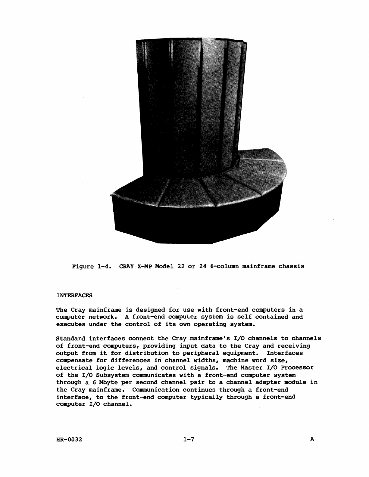
Figure
INTERFACES
The
Cray
computer
executes
1-4.
mainframe
network.
under
the
CRAY
is
A
front-end
control
X~P
Model
designed
of
22
or
for
use
computer
its
own
24 6-column
with
front-end
system
operating
mainframe
is
self
system.
chassis
computers
contained
in
and
a
Standard
of
front-end
output
from
compensate
electrical
of
the
I/O
through
the
a 6 Mbyte
Cray
interface,
computer
HR-0032
interfaces
computers,
it
for
for
differences
logic
levels,
Subsystem
per
mainframe.
to
the
I/O
channel.
connect
providing
distribution
tn
and
communicates
second
Communication
front-end
the
Cray
input
to
peripheral
channel
control
with a front-end
channel
continues
computer
1-7
mainframe's
data
to
equipment.
widths,
machine
signals.
pair
to a channel
through a front-end
typically
I/O
the
channels
Cray
and
to
receiving
Interfaces
The
word
Master
computer
size,
I/O
system
adapter
Processor
module
through a front-end
channels
in
A
Page 20
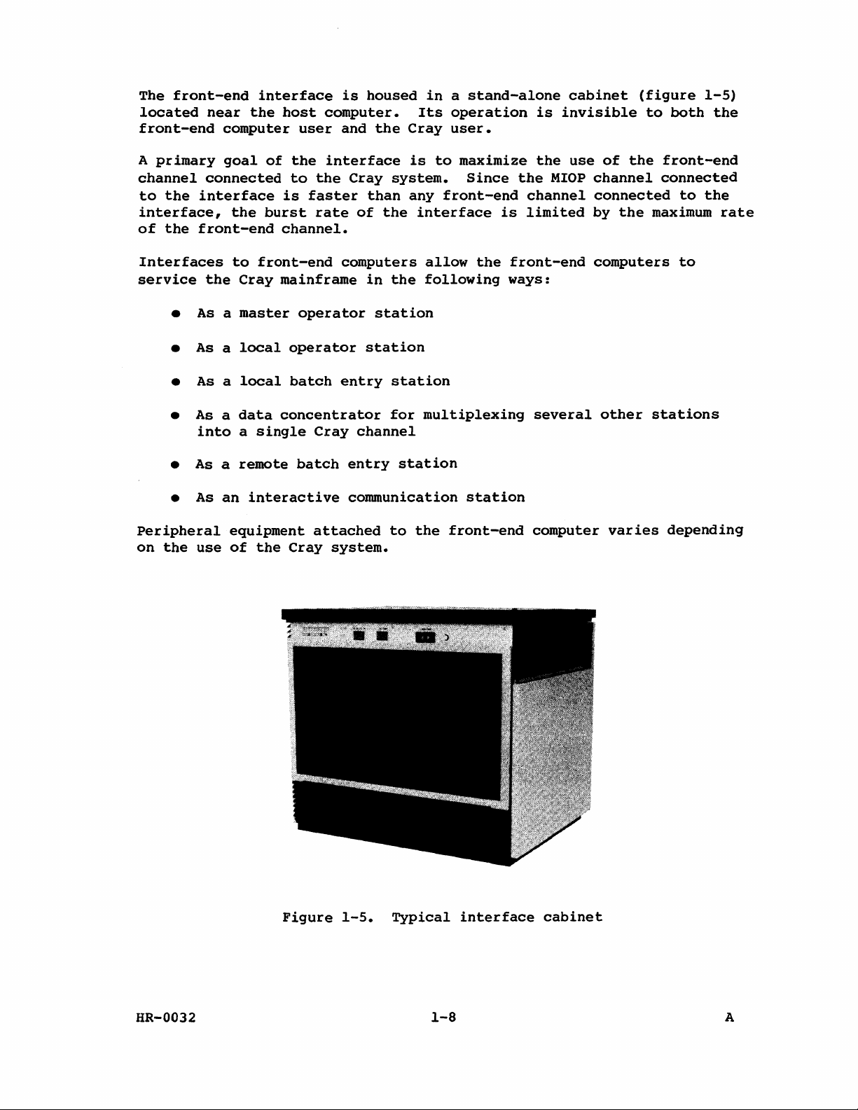
The
front-end
located
front-end
A
primary
channel
to
the
interface,
of
the
near
the
computer
goal
connected
interface
the
front-end
interface
host
user
of
the
to
is
faster
burst
channel.
is
housed
computer.
and
interface
the
Cray
than
rate
of
the
system.
the
in a stand-alone
Its
operation
Cray
is
user.
to
maximize
Since
any
front-end
interface
is
is
the
the
MIOP
channel
limited
cabinet
invisible
use
of
channel
connected
by
(figure
the
the
to
both
front-end
connected
to
maximum
1-5)
the
the
rate
Interfaces
service
•
As a master
•
As a local
•
As a local
•
As a data
into a Single
•
As a remote
•
As
Peripheral
on
the
use
to
the
Cray
an
interactive
equipment
of
front-end
mainframe
operator
operator
batch
concentrator
Cray
batch
attached
the
Cray
computers
in
the
station
station
entry
station
for
channel
entry
station
communication
to
the
system.
allow
following
the
ways:
multiplexing
station
front-end
front-end
several
computer
computers
other
stations
varies
to
depending
HR-0032
Figure
1-5.
Typical
1-8
interface
cabinet
A
Page 21

I/O
SUBSYSTEM
The
I/O
X-MP
Computer
a
Buffer
transfer
devices,
Memory
Subsystem,
Systems
Memory,
between
and
the
and
the
shown
and
front-end
I/O
Central
in
figure
and
has
two,
required
computers,
Subsystem's
Memory
of a Cray
1-6,
three,
interfaces.
peripheral
Buffer
is
standard
or
four
It
is
Memory
or
mainframe.
on
all
I/O
Processors
designed
devices,
between
models
for
fast
storage
its
Buffer
of
CRAY
(lOPs),
data
Four
Master
Auxiliary
one
Each
computation
are
Subsystem.
types
of
lOP (MIOP), a
lOP (XIOP).
BIOP. The number
lOP
of
section,
independent
Each
Memory.
Master
The
standard
interfaces
of
the
mainframe
with
the
entire
The
Buffer
Central
I/O
group
the
MIOP. The
over
Cray
I/O
Subsystem.
I/O
Memory
transferred
Memory
The
This
disk
DMA
100
through a 100
Disk
I/O
processor
storage
port
Mbyte
to
per
connect
I/O
Processors
the
I/O
and
lOP
Processor
of
station
station
MIOP
a 6 Mbyte
Operating
Processor
and
through
Processor
can
units.
second
Buffer
All
of
DIOPs
Subsystem
and
an
handle
also
has
(MIOP)
t
peripherals
also
per
System
(BIOP)
the
mass
the
BIOP's
Mbyte
(DIOP)
handle
The
to
up
DIOP
Buffer
channel
may
be
configured
lOP (BIOP), a
I/O
Subsystems
and
XIOPs
has
a memory
input/output
some
portion
six
direct
controls
peripherals.
to
one
connects
second
(COS)
storage
Local
per
second
is
to
four
uses
is
used
to
channel
to
the
devices.
Memory
disk
one
Memory,
pair
to
the
Disk
must
is
section,
section.
of
the
memory
the
The
direct
Buffer
coordinate
main
channel
for
additional
controller
DMA
port
and
another
mainframe
in
an
lOP (DIOP)
have
site
dependent.
I/O
access
front-end
Peripheral
memory
Memory
pair.
link
between
Data
to
the
pair.
for
DMA
I/O
Subsystem:
and
at
least
a
control
Input/output
requirements
ports
interfaces
Expander
access
and
to
The
MIOP
communicates
the
activities
the
from
mass
mainframe's
disk
units
each
Central
storage
with
controller,
port
to
Memory.
a
an
one
MIOP
and
section,
sections
for
the
to
its
local
and
(DMA)
port
the
of
the
mainframe's
storage
is
Central
units.
up
to
16
one
connect
a
a
the
Auxiliary
The
and
interfaces
Each
controller
XIOP
uses
connect
t The
link
HR-0032
one
with
term
to
I/O
to a maximum
can
DNA
Buffer
station
the
front
Processor
handle
port
for
Memory.
means
end
or
(XIOP)
of
up
each
both
can
is
four
to
four
controller
hardware
act
1-9
used
BMC-4
block
for
Block
multiplexer
and
and
software.
as a limited
block
multiplexer
Multiplexer
another
front
Controllers.
channels.
DMA
port
Station
end
(as
channels
The
to
is
the
the
MIOP).
A
Page 22

I/O
Subsystem
BIOP
and
Memory.t
The
CPU
input/output
in
section
Manual,
CRI
Subsystem.
hardware
DIOP
2
or
of
publication
XIOP
this
allows
of
the
section
manual.
HR-0030,
for
simultaneous
I/O
Subsystem
for
Cray
Refer
to
for a complete
data
and
the
dual-processor
the
I/O
Subsystem
description
transfers
mainframe's
systems
Reference
of
between
Central
is
described
the
the
I/O
t
Software
XIOP
HR-0032
is
currently
to
Figure
support
the
not
1-6.
100
Mbyte
available.
I/O
Subsystem
1-10
per
second
chassis
channel
pair
to
the
A
Page 23
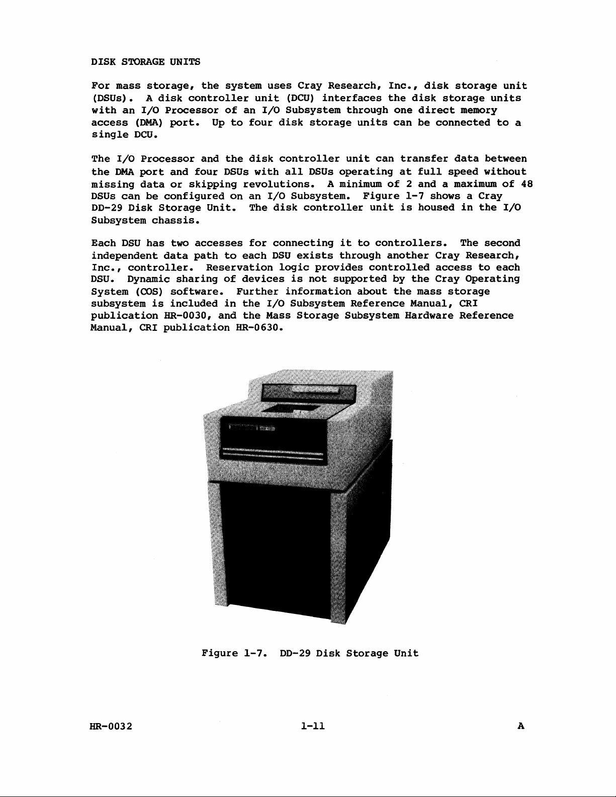
DISK
For
STORAGE
mass
(DSUs). A
with
access
single
The
the
missing
DSUs
DD-29
an
DCU.
I/O
DMA
can
Disk
I/O
(DNA)
Processor
port
data
Subsystem
UNITS
storage,
disk
Processor
port.
and
or
be
configured
Storage
chassis.
the
system
controller
of
Up
to
and
the
four
DSUs
skipping
on
Unit.
an
four
disk
uses
unit
I/O
with
Cray
(DCU)
Subsystem
disk
controller
all
revolutions.
an
I/O
Subsystem.
The
disk
Research,
interfaces
through
storage
unit
DSUs
operating
A minimum
controller
units
can
Figure
unit
Inc.,
the
one
can
disk
disk
direct
be
transfer
at
full
storage
storage
memory
connected
data
speed
units
between
without
of 2 and a maximum
1-7
is
shows a
housed
in
Cray
the
unit
to
of
I/O
a
48
Each
DSU
independent
Inc.,
DSU.
System
controller.
Dynamic
(COS)
subsystem
publication
Manual,
CRI
has
two
data
sharing
software.
is
included
HR-0030,
publication
accesses
path
to
Reservation
of
Further
in
and
HR-0630.
for
connecting
each
DSU
devices
the
I/O
the
Mass
exists
logic
is
provides
not
information
Subsystem
Storage
it
to
controllers.
through
controlled
supported
about
Reference
Subsystem
another
by
the
the
mass
Manual,
Hardware
The
Cray
access
Cray
storage
CRI
Reference
second
Research,
to
each
Operating
HR-0032
Figure
1-7.
DD-29
1-11
Disk
Storage
Unit
A
Page 24
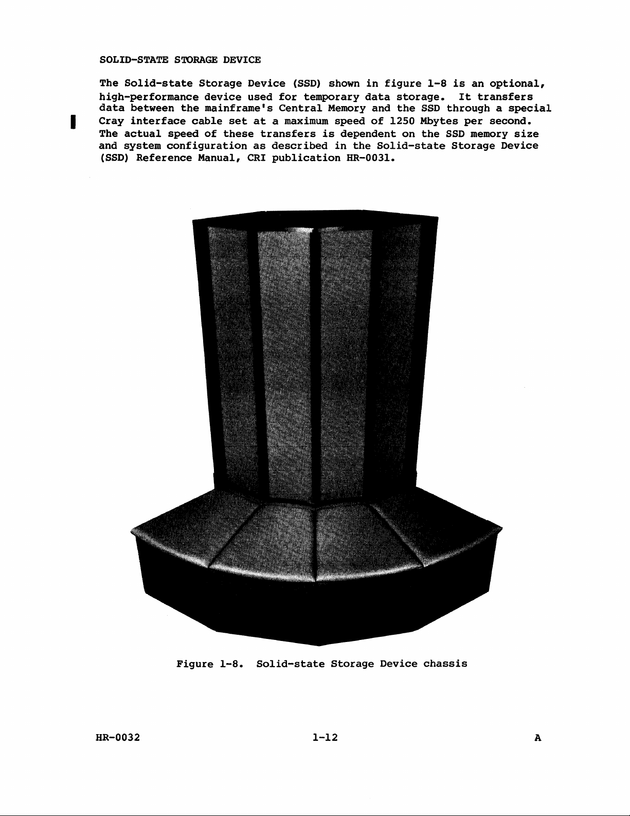
SOLID-STATE
The
Solid-state
high-performance
data
I
Cray
The
actual
and
system
(SSD)
between
interface
speed
configuration
Reference
STORAGE
Storage
device
the
mainframe's
cable
of
Manual,
DEVICE
Device
used
set
at a maximum
these
transfers
as
CRI
(SSD)
for
temporary
Central
is
described
publication
shown
Memory
speed
dependent
in
the
HR-003l.
in
figure
data
storage.
and
the
of
1250 Mbytes
on
Solid-state
1-8
is
an
It
transfers
SSD
through a special
per
the
SSD
memory
Storage
optional,
second.
size
Device
HR-0032
Figure
1-8.
Solid-state
Storage
1-12
Device
chassis
A
Page 25
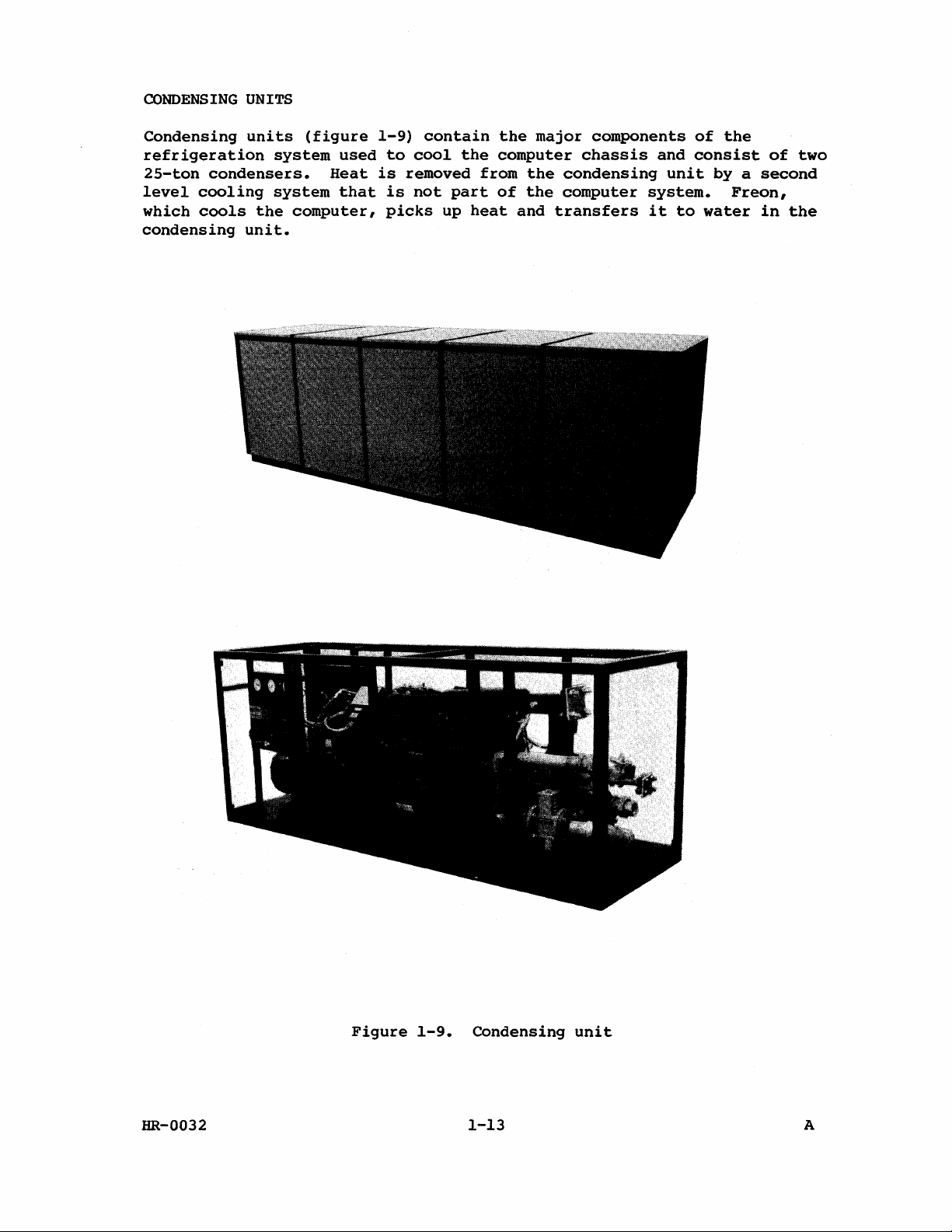
CONDENSING
UNITS
Condensing
refrigeration
25-ton
level
which
condensers.
cooling
cools
condensing
units
the
unit.
(figure
system
system
computer,
used
Heat
that
1-9)
to
is
removed
is
picks
contain
cool
not
part
up
the
from
heat
the
major
computer
the
of
the
and
transfers
components
chassis
condensing
computer
of
and
consist
unit
system.
it
to
the
of
by a second
Freon,
water
in
two
the
HR-0032
Figure
1-9.
Condensing
1-13
unit
A
Page 26
I
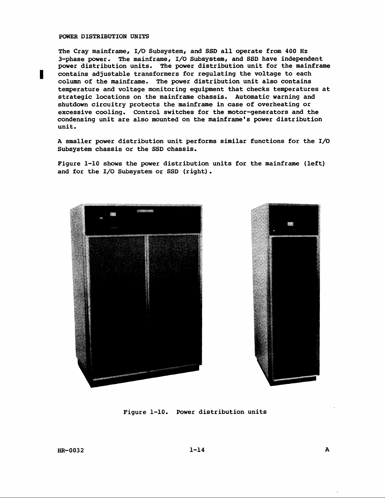
POWER
The
3-phase
power
contains
column
temperature
strategic
shutdown
excessive
condensing
unit.
A
Subsystem
DISTRIBUTION
Cray
power.
distribution
of
circuitry
smaller
mainframe,
The
adjustable
the
mainframe.
and
voltage
locations
cooling.
unit
power
chassis
are
distribution
UNITS
I/O
Subsystem,
mainframe,
units.
transformers
monitoring
on
the
protects
control
also
mounted
or
the
SSD
I/O
The power
for
The power
mainframe
the
mainframe
switches
on
unit
performs
chassis.
and
SSD
all
Subsystem,
distribution
regulating
distribution
equipment
chassis.
in
for
the
the
mainframe's
similar
operate
and
SSD
unit
the
unit
that
checks
Automatic
case
of
motor-generators
from 400
have
for
voltage
also
temperatures
warning
overheating
power
functions
distribution
Hz
independent
the
mainframe
to
each
contains
and
or
and
the
for
the
at
I/O
Figure
and
for
1-10
the
shows
I/O
Subsystem
the
power
or
distribution
SSD
(right).
units
for
the
mainframe
(left)
HR-0032
Figure
1-10.
Power
1-14
distribution
units
A
Page 27
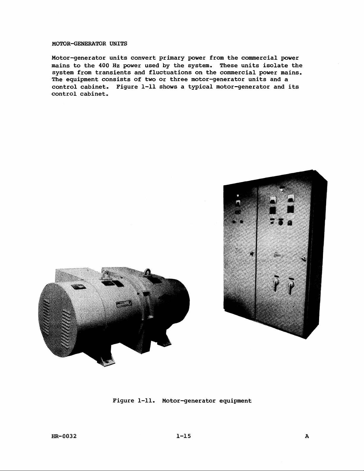
MOTOR-GENERATOR
UNITS
Motor-generator
mains
system
The
control
control
to
the
from
equipment
cabinet.
cabinet.
transients
units
400
Hz
consists
convert
power
Figure
used
and
fluctuations
of
two
1-11
primary
by
the
power
system.
on
or
three
motor-generator
shows a typical
from
the
These
the
commercial
motor-generator
commercial
units
isolate
power
units
and
power
mains.
and
the
a
its
HR-0032
Figure
1-11.
Motor-generator
1-15
equipment
A
Page 28
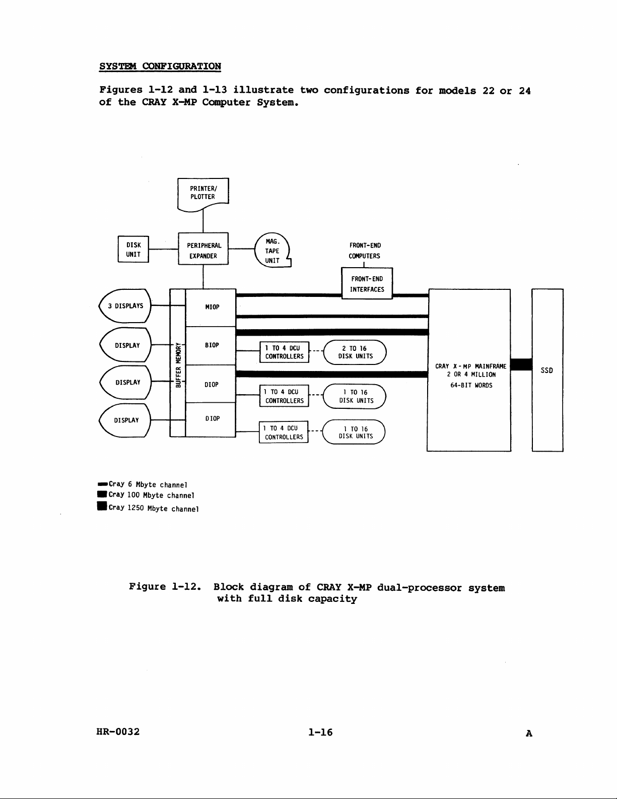
SYSTEM
CONFIGURATION
Figures
of
the
1-12
CRAY
and
x~p
1-13
illustrate
Computer
MIOP
SlOP
DIOP
System.
two
configurations
FRONT-END
COMPUTERS
FRONT-END
INTERFACES
for
models
CRAY
X·
MP
2
OR 4 MILLION
64·BIT
22
or
MAINFRAME
WORDS
24
SSD
_Cray
• Cray 100 Mbyte channel
• Cray 1250 Mbyte channel
6 Mbyte channel
Figure
1-12.
DIOP
Block
with
diagram
full
disk
of
CRAY
capacity
X-MP
dual-processor
system
HR-0032
1-16
A
Page 29
MIOP
BIOP
DIOP
XIOP
1
TO
BLOCK
MULTIPLEXER
CONTROLLERS
FRONT-END
COMPUTERS
FRONT-END
INTERFACES
CRAY
X -
MP
MAINFRAME
2
OR 4 MILLION
64-BIT
WORDS
2
- - -1
TO 8 CHANNELS
SSD
_Cray
• Cray 100 Mbyte channel
.Cray
6 Mbyte channel
1250 t4byte channel
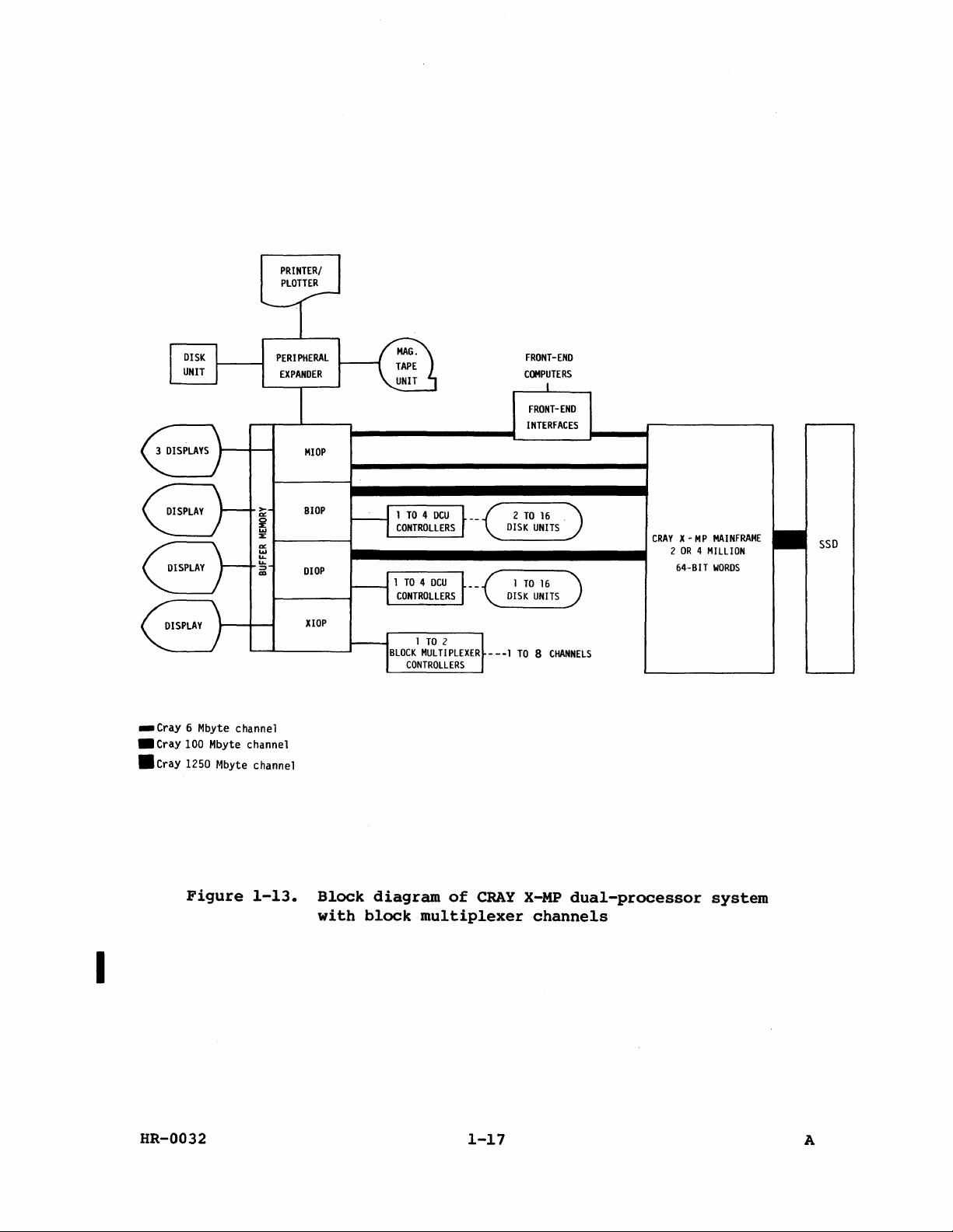
Figure
I
HR-0032
1-13.
Block
with
diagram
block
of
CRAY
multiplexer
1-17
X-MP
dual-processor
channels
system
A
Page 30

Page 31

CPU
INTRODUCTION
SHARED
RESOURCES
2
I
Both
Central
million
Memory
S
words
of
Central
Memory,
input/output
the
following
CENTRAL
Central
access
Standard
sequentially
72
Central
(ns).
(scalar)
(vector)
(intermediate
The
CPs.
is 2 words
MEMORY
Memory
memory
words
bits
with
Memory
Access
to
maximum
per
Transfer
32
parcels
Central
register
Processing
the
section.
pages.
consists
(RAM)
Memory
with
addressed
64
data
cycle
time,
an
operating
registers.
and
address)
transfer
CP;
for A and S registers
of
instructions
(8
words)
per
CP.
Units
inter-CPU
These
of
and
is
sizes
32
banks.
words
bits
time
the
time
register,
Access
16
or T (intermediate
rate
per
(CPUs)
communication
areas
a number
shared
and 8 check
is 4 clock
required
CPs +
per
CP.
are:
Banks
reside
is
time
block
CPU
to
For
by
instruction
of a system
common
of
banks
the
CPUs
2
million
are
independent
in
sequential
bits.
periods
to
fetch
14
CPs
is
17
CPs +
length
for
B,
T,
per
CPU,
the
I/O
share
section,
to
the
CPUs
of
solid-state,
and
the
words
(CPs)
an
(133
vector
for a block
scalar)
and V registers
it
buffers
section,
with
of
banks.
or
operand
ns)
for A (address)
register.
is
one
the
and
the
are
described
I/O
section.
16
each
Each
38
nanoseconds
from
length
transfer
word
occurs
the
transfer
mainframe's
random
banks
other;
for
is
every
at a rate
and
word
Central
and
a V
to
a B
three
2
rate
in
4
is
Central
in
the
following
•
Shared
• 2
• 64
•
16
• 4-CP bank
•
Single
• 3
HR-0032
Memory
million
data
or
words
features
paragraphs.
access
or 4 million
bits
32
interleaved
cycle
error
per
CP
are
summarized
from
both
and 8 error
time
correction/double
transfer
CPUs
words
correction
banks
rate
of
error
to
2-1
below
integrated
B,
and
bits
detection
T,
and V registers
are
circuit
per
described
memory
word
(SECDED)
per
in
detail
CPU
A
Page 32

• 1 word
• 8 words
• 2 words
activity
per 2 CP
per
CP
per
CP
except
transfer
transfer
transfer
instruction
rate
rate
rate
to A and S registers
to
instruction
to
I/O
concurrent
fetch
and
exchange
buffers
with
per
all
CPU
memory
I
MEMORY
Memory
Data
ORGANIZATION
is
transfers
correction,
organized
16-bank
32-bank
As
path
eight
phasing
phasing
shown
into
memory
organized
to
double
into
in
each
four
figure
of
references
and
error
is
standard
is
standard
2-1,
the
SECTION
Banks
to
provide
from
detection
sections
each
four
per
0
0,4,10,14,t
20,24,30,34
fast,
memory
efficient
are
corrected
(SECDED).
with 4 or 8 banks
for a 2-million
for a 4-million
CPU
is
connected
sections.
clock
"'-_+1
This
period.
CPU
ports
ABC
CPU
t4----+I
access
with
single
Central
in
each
word
system
word
to
system
an
independent
configuration
SECTION
Banks
2
2,6,12,16,t
22,26,32,36
for
all
Memory
section.
(model
(model
allows
CPUs.
error
is
22),
24).
The
and
access
up
to
Figure
t Low-numbered 4
HR-0032
SECTION 1
Banks
1,5,11,15,t
21,25,31,35
2-1.
banks
Central
a
dual-processor
in
each
CPU
path
selection
ABC
CPU
ports
Memory
section
2-2
SECTION
Banks
organization
system
are
in a 16-bank
3
3,7,13,17,t
23,27,33,37
for
system.
A
Page 33

MEMORY
ADDRESSING
Memory
and
addressing
number
l2-column
Memory
A word
in
next
bits
A word
in
addressing
in a 32-bank
figure
l4-bit
specify
in a l6-bank
figure
banks.
high-order
of
banks)
dual-processor
2-2.
The
field
one
chip
address address
select
Figure
2-3.
The
3
next
bits
In
l4-bit
is
dependent
and
memory
systems
for
6-column
memory
is
addressed
low-order 5 bits
specifies
on
Chip
2-2.
memory
this
specify
an
the
module.
6-column
is
case,
field
one
Internal
addressed
the
specifies
chip
on
system
size.
is
memory
Memory
described
mainframe
in a maximum
specify
address
within
bit
in
chip
memory
address
in a maximum
low-order 4 bits
an
on
the
module.
architecture
addressing
in
one
the
address
the
of
the
chip.
5-bit
bank
(32
specify
within
t
for
following
of
22
bits
32
banks.
The
banks)
of
21
bits
one
the
(chip
size
6-column
paragraphs.
as
shown
The
high-order
as
shown
of
the
chip.
The
and
3
16
t Hardware
software,
will
receive 5 significant
high-order
by
the
correction.
HR-0032
Figure
assembles
when
bit
software
Chip
address
select
2-3.
the
6-column
address
assembling
(bit 4 counting
when
assembling
Internal
address
chip
memory
using a 4-bit
the
address
bits
from
right
the
2-3
bit
in
address
for
the
Exchange
to
left
address
4-bit
bank
bank
memory
from
for
(16
banks)
field.
error
Package.
0)
memory
The
correction,
must
be
error
The
discarded
A
Page 34

I
Memory
addressing
for
l2-column
mainframe
I
A word
in
next
bits
A word
in
banks.
high-order
in a 32-bank
figure
l2-bit
specify
in a l6-bank
figure
The
2-4.
field
Figure
2-5.
next
5
one
bits
memory
The
low-order 5 bits
specifies
chip
on
the
Chip
address
select
2-4.
memory
In
this
l2-bit
specify
Chip
address
select
12-column
case,
field
one
is
addressed
an
address
module.
Internal
address
is
addressed
the
specifies
chip
Internal
address
in a maximum
specify
within
bit
in
chip
memory
in a maximum
low-order 4 bits
an
on
the
bit
in
chip
one
the
address
address
module.
of
chip.
5-bit
bank
(32
specify
within
t
4-bit
bank
of
the
banks)
of
22
32
The
21
bits
banks.
high-order
bits
one
of
the
chip.
as
as
shown
The
shown
the
The
5
16
MEMORY
Both
Port
Ports
t Hardware
ACCESS
CPUs
C,
and
A,
B,
software,
will
high-order
by
correction.
receive
the
Figure
have
software
four
I/O.
and C are
assembles
when
5
bit
2-5.
memory
Each
assembling
significant
(bit 4 counting
when
l2-column
access
port
used
the
is
for
address
assembling
the
bits
memory
ports,
capable
CPU
using a 4-bit
address
right
of
register
from
the
address
address
referred
making
transfers.
for
the
Exchange
to
left
one
bank
memory
from
for
(16
banks)
to
as
reference
field.
error
Package.
0)
memory
Port
A,
The
correction,
must
be
error
Port
per
The
discarded
B,
CP.
HR-0032
2-4
A
Page 35

B,
T,
•
•
and
•
vector
Vector
use
Port
Vector
use
Port
Vector
and
scalar
memory
read
A.
read
B.
store,
instructions
(block
(block
B,
or T store
instructions
reads
reads
only),
only),
(100-137)
issue
to a particu1ar
B
read
T
read
instructions
use
instructions
instructions
(177,
Port
C.
035,
memory
(176,
(176,
and
037)
port:
034)
036)
Once
an
references
The
references
completed
examined
transfer
is
busy,
on
the
number
The
bidirectional
disable
are
provided
the
bidirectional
allowed
allows
block
to
the
transfers
issuing
designated
software
sequential
instruction
are
made
in
sequence
individually
may
not
issue
and
for
be
is
blocked.
type
each
issues
for
to a port,
that
instruction.
element
through a port.
for
possible
continuous.
Total
of
conflicts
that
of a block
However,
conflicts,
If
an
instruction
execution
encountered
port
is
transfer
since
the
time
during
reserved
(V,B,T)
data
requires
of
the
each
flow
transfer
the
until
are
reference
for
a
transfer.
*******************************************************
CAUTION
Because
examined
(memory
detect
sequential
concurrent
for
read
overlap
where
this
operation.
block
before
hazard
condition
reads
write
and
or
conditions),
occurs
writes
write
the
and
are
before
software
ensure
not
read
must
*******************************************************
memory mode
(0026),
to
and
resolve
memory mode
operate
program
are
it
and
the
memory
or
a mechanism,
memory
operation
the
complete
these
concurrently
to
wait
past
the
transferred
register
wherever
enable
(0025),
memory
cases
is
and
clear,
within
until
the
last
conflict
data
is
locations.
necessary
within a CPU
bidirectional
reference
assure
block
that
CPU.
references
resolution
being
transmitted
Instruction
in
the
or
between
(0027)
sequential
reads
and
Instruction
of
stage
program,
CPUs.
memory mode
instructions
operation.
writes
all
within
to
0027
provides
to
preceding
the
guarantee
made
a
port
are
0027
the
all
and
is
that
depends
If
not
CPU
Issue
of
available,
scalar
HR-0032
references
scalar
ensuring
memory
references
sequential
within a CPU.
requires
operation
2-5
Ports
between
A, B,
block
and C to
transfers
be
and
A
Page 36

A
scalar
conflict
scalar
the
preceding
reference
occurs,
reference
scalar
conflict
one
holds
is
more
scalar
issue
reference.
detected
reference
if
the
in
conflict
CP 3 of
is
allowed
condition
execution.
to
issue.
still
If
A
exists
a
third
for
Scalar
cpu.
conflict
One-half
port.
A,
When
memory
proceeds
Then
Instruction
B,
or
an
the
references
resolution
of
the
The
I/O
C.
instruction
ports
is
and
references
referencing
A
fetch
certain
this
must
execution.
before
buffer
This
to
utilizes
generated
memory
to
arise
presents
the
always
0027
stage
cpu
I/O
port
can
fetch
inhibited.
of
sequence
conditions,
happen,
before
The
the
scalar
boundary
same
area
dynamic
is
actually
is
fetched
execute
detects
channels
be
32
the
however,
out-of-buffer
is
a
problem
when
within
active
request
When
banks
eight
that
follows a scalar
complete
the
scalar
store
crossed
in
memory.
coding
in
into
in
the
all
the
CPU
reference
regardless
occurs,
memory
in
the
ports
NOTE
an
out-of-buffer
is
in
without
only
should
memory
the
instruction
order
scalar
is
next
is
before
store
condition
CP 2 of
if
the
Therefore,
ensure
before
they
issuing
memory
of
all
referencing
quiet
4 CPs (6 CPs
enabled.
the
is
doing a branch.
fetch
are
references
it.
through
the
activities
(0
to 3 CPs),
store
in
can
execution
software
that
that
buffers.
can,
store.
condition
CP 2 of
occur
and
the
area
issued
are
each
from
if
under
For
if
store
that
code
of
within
past
16
a
are
the
CPU's
on
Ports
the
eight
the
fetch
banks).
a
I/O
An
exchange
exchange
When
ports
bank
the
HR-0032
the
of
the
exchange
is
a
write.
reference
other
requires
request
exchange
the
other
proceeds
referenced
A
fetch
is
complete
CPU
is
all
is
made.
request
cpu
is
and
twice
request
and
enabled.
activities
is
made,
inhibited.
references
during
follows
then
referencing
within
all
referencing
When
16
this
time,
immediately
2-6
a
memory
banks
once
from
cpu
to
is
in
the
for a read
after
the
complete
from
quiet
next
the
four
the
exchange
memory
before
four
(0
to
21 CPs. Each
and
once
the
memory
3 CPs) ,
for
ports
of
A
Page 37

Conflict
resolution
During
are
reference,
port
Three
I
Simultaneous
Bank Busy
or
Resolution
ports
Simultaneous
two
of
I
access
Simultaneous
Simultaneous
Section
I
more
Resolution
port
I
hold
held 1 CP
each
examined
is
allowed
types
between
in
the
or
more
this
conflict
priorities).
Access
ports
is
allowed
(see
clock
for
memory
the
reference
until
of
memory
Bank,
conflict
CPUs
of
of
subsection
because
CPU
Bank
ports
Bank
Bank
in
this
the
this
requesting
are
is
conflict
to
period,
and
- The Bank Busy
conflict
held
conflict
in
different
based
All
conflict.
conflict.
same
conflict
proceed,
below
of a Section
references
access
is
held
the
conflict
access
Section
a
occurs
1,
- The
on a priority
ports
- The
CPU
requesting
is
all
on
conflicts.
conflicts
Access.
bank
2,
CPUs
in a CPU
A Bank Busy
Section
based
Memory
Access
to
the
and
no
further
is
resolved.
can
conflict
currently
when
or
Simultaneous
other
the
3 CPs
because
requesting
(see
are
conflict
Access
any
on
priority.
ports
access
conflict.
memory
If a conflict
occur:
is
in a reference
bank
Bank
SUbsection
held I CP
conflict
bank
involved
priorities).
ports
referencing
Bank
caused
cycle
of
a Bank Busy
conflict
the
same
always
in
the
The
in
occurs
Busy,
by
any
is
bank.
below
because
follows
is
caused
same
highest
in
this
the
system
for
from
that
port
cycle.
complete.
conflict.
is
caused
Resolution
on
Memory
of
a
a
by
section.
priority
conflict
The
port
a
within
All
by
two
is
or
Memory
The
following
•
•
•
access
Intra-CPU
determined
Inter-CPU
I/O
CPUs.
priorities
priorities
Any
port
than a port
sequence.
Among
the
relative
first
priority:
priority:
by
the
with
all
ports
issued
priority:
are
following
an
with
with
time
having
the
I/O
used
the
odd
an
of
every
even
the
ports
to
resolve
priority
conditions:
increment
increment,
the
same
issue
determines
highest
4 CPs
are
memory
between
always
type
of
priority.
the
priority
always
access
Ports
has a higher
regardless
increment
the
priority,
between
lowest
priority,
A,
B,
of
conflicts.
and C is
priority
their
(odd
or
with
CPUs
within
issued
even),
the
changes.
HR-0032
2-7
A
Page 38

l6-BANK
The
increase
of
performance
predictable
conflicts.
For
only
Maintenance
or
upper
PHASING
effect
of
maintenance
16
banks
banks.
of
l6-bank
2 CPs
degradation
since
purposes,
and
is
accomplished
for
it
use
phasing
filling
largely
a
either
on
instruction
for
16
results
32-bank
the
by
setting
instruction
banks
lower
instead
from
system
or
the
fetches
buffers.
of
an
increased
can
be
upper
half
bank
Otherwise,
32
modified
of
select
is a predictable
the
banks
number
switch
is
to
memory.
not
of
memory
operate
to
the
amount
readily
with
lower
MEMORY
A
single
between a CPU
can
If a single
automatically
2
bits
corrected.
interrupt
more
ERROR
be
returned
of
bits
error
bit
the
In
options
in
o
Data
Bits
63
64
Check
Bits
71
CORRECTION
correction/double
and
memory.
to
the
CPU
of a data
corrected
same
either
selected
error,
Memory
data
case,
results
before
word
~
SECDED
with
word
are
the
to
allow
are
...
Data
-
error
assures
consistent
is
altered,
passing
altered,
CPU
ambiguous.
Error
Detect
detection
the
can
processing
Fanin
that
precision
the
data
the
error
be
interrupted,
-
(SECDED)
data
single
word
of
the
Error
Correct
written
(figure
error
to
the
is
detected
depending
error.
network
into
2-6).
alteration
computer.
but
For 3 or
is
used
memory
not
on
CPU
is
If
The
SECDED
correction
t Hamming, R.W.,
Technical
HR-0032
error
codes
Journal,
Figure
processing
devised
"Error
2-6.
by R.
Detection
29,
scheme
No.2,
Memory
is
W.
Hamming.
and
pp.
2-8
data
147-160
path
based
t
Correcting
on
error
An
(April,
with
8-bit
Codes,"
SECDED
detection
check
1950).
byte
Bell
and
is
System
A
Page 39

appended
The 8
of
check
data
determine
indicates
Thus,
of
227,
check
bits
229,
to
bits.
the
that
21,
and 2
the
64-bit
bits
are
Figure
state
data
bit 0 is
23, 25,
31
through
data
generated
2-7
shows
of
each
bit
contributes
the
bit
27,
29,
255.
word
as
check
that
211,
before
even
the
bit.
bits
to
the
parity
An X
the
makes group
213, 215,
data
bits
of
the
in
generation
parity
217,
is
written
for a specific
data
the
horizontal
word
of
even
219,
221,
used
that
for
223,
in
memory.
to
row
check
the
225,
group
bit.
group
The 8
check
location.
used
check
bits
that
error
check
check
check
check
check
check
check
check
to
bits.
(S
occurred
is
bit
0
bit
bit
bit
bit
4
bit
bit
6
bit
7 x
bits
When
generate
bits).
assumed.
1
2
3
5
7
6
2
2 ..
..
2
x x x
x
x x
x
The
(l=No
CHECK
5
..
2
x
....
and
the
read
from memory,
a new
resulting
The
states
compare).
BYTE
3
2
2 ..
..
.. 1 2'+0
2
2
x
x
x
x
set
data
word
of
check
8
comparison
of
these S bits
39
2
x
x
If
2
are
stored
the
same
bits,
bits
all
syndrome
x
38
37
35
36
2
2
2
234
x
x
in
64-bit
which
are
are
233
232
x
x
memory
matrix
are
called
all
bits
2
at
compared
syndrome
symptoms
are
0,
x
x
31 230 229
x
x x
2
x x
of
28
the
figure
with
of
no
x
227
2
x
x
x
x
same
t
any
memory
26 225
224
x
x
x
2-7
the
error
is
old
23
2
222
221 220 219
x
t Syndrome: any
certain
type,
HR-0032
218 217
216
x x
Figure
set
of
condition,
15
13
2
214
2
212 211
x
x x
x x
2-7.
Error
characteristics
etc.
Websters
2-9
10
2
x
8
29
2
x
x
correction
regarded
New
27
x
x
x
matrix
as
World
6 25
2
x
x
3
2"
2
x
x
x
x
x
identifying
Dictionary.
22
21
2°
x
x
x
x
x
x
x
x
a
A
Page 40

Any
change
syndrome
as
an
even
The
matrix
•
If
•
If
•
If
SO
bit
•
If
bits
have
bit
•
If 3 or
bits
of
bits
number
is
designed
all
syndrome
only
more
through
errors)
more
is
occurred.
in
error.
is
state
to
1 syndrome
than
odd,
more memory
odd
of a single
be
set
of
syndrome
than
1 syndrome
S7
is
occurred
1 syndrome
then a single
and
so
bits
The syndrome
results
to
1.
that:
bit
even,
bits
bit
in
A
double
bits
are
is
then a double
within
set
0,
no
1,
bit
is 1 and
the
bit
is 1 and
and
are
are
ambiguous.
the
bits
in
memory
error
to
error
associated
data
correctable
can
error,
causes
1.
is
the
error
bits
the
be
the
(an
error
assumed.
check
parity
(or
or
check
parity
error
decoded
parity
an
odd
in 2 bits)
bit
of
syndrome
an
even
bits.
of
all
is
to
of
number
is
in
number
syndrome
assumed
identify
all
syndrome
of
appears
error.
bits
of
to
the
Modules
used
storage,
I
to
INTER-CPU
The
hardware
real-time
Scalar
registers,
and
REAL-TIME
The
by
(CP)
9.5
program
of
from
involved
for
SECDED
check
Appendix D
COMMUNICATION
inter-CPU
for
clock.
(ST),
described
CLOCK
mainframe
both
CPs. However,
CPUs. Programs
counter.
nanosecond
execution,
other
bit
for
communication
communication
and
with
in
contains
This
clock
tasks
with
include
Semaphore
their
the
if
generating
generation,
information
The
Real-time
sources
following
one
counter
period.
it
can
in
such
an
interrupt
logic
SECTION
can
that
on
section
between
(SM)
and
Real-time
be
is
Since
be
used
an
application,
and
interpreting
can
be
and
error
SECDED
of
the
the
two CPUs,
Clock
registers
paragraphs.
timed
64
occurs
(RTC),
destinations,
Clock
precisely
bits
wide
the
clock
to
time
before
used
for
detection
maintenance
mainframe
for
Shared
are
shared
are
(RTC)
and
the
the
register
by
advances
advances
program
counting
the
the
8-bit
verifying
and
correction.
functions.
contains
control,
Address
by
shown
using
synchronously
to
can
end
time
the
in
which
the
one
an
contain
check
check
special
and
(SB),
CPUs.
figure
clock
count
exact
is
read.
byte
bit
for
Shared
These
is
shared
period
each
number
counts
Refer
a
2-8
with
HR-0032
2-10
A
Page 41

Instructions
0014jO
072ioO
A
program
instruction
all
CPOs
software
register.
used
reads
0014jO.
at
the
should
with
RT
sj
si
RT
the
same
ensure
~
--E-----------41
Ai
----
SBj
~------:~=r=L.,
the
CP
counter
Loading
time.
that
__
RTC
register
Enter
the
Transmit
using
or
reading
If
more
only
~~~=='==:
than
one
I--~....L"o"---------,l-
RTC
(RTC)
instruction
CPU
RTC
are:
register
to
the
CP
one
CPU
enters
It----------...i_-
with
si
072
counter
is
in
a
value
and
can
monitor
into
(Sj)
resets
occur
mode,
this
~~
Ai
SBj
it
from
with
the
INTER-CPU
Three
control
identical
between
registers,
Semaphore
Each CPU's
registers
STj
~--~:Z;===L-,
Si
S~_.---~~r=~_.
Figure
COMMUNICATION
sets
2-8.
of
AND
shared
CPUs. Each
eight
(SM)
Cluster
is
64-bit
registers.
Number
accessed
Shared
by a CPU
Shared
CONTROL
set
(CLN)
~~~~------------~-
~+_~~----------~
registers
registers
contains
Scalar
register
(clustering).
and
are
eight
(ST)
registers
determines
real-time
used
24-bit
The
__
clock
for
communication
Shared
and
32
which
CLN
register
Si
STj
Si
S~
Address
I-bit
set
of
is
and
(SB)
shared
loaded
HR-0032
2-11
A
Page 42

from
instruction
The
or 3 allow
Value 0 prevents
is
for
value.
2,
registers.
the
Exchange
CLN
register
0,
instructions
the
instructions
If
or
3),
0014j3.
the
the
then
Package
can
CPU
any
CLN
the
or
contain
to
access
access
regarding
returning
registers
two
CPUs
if
the
CPU
is
one
of
four
different
one
of
the
three
to
shared
the
shared
values
in
both
share a common
registers
registers
to
Ai
CPUs
in
are
set
monitor
sets
or
si,
set
of
values.
of
by
the
become
which
to
SB, ST,
mode,
shared
CPU.
the
through
Values
registers.
If
no-ops,
return
same
and
value
SM
1,
the
except
a 0
2,
value
(1,
I
Access
occur
For
CPU 1 enter
for
Semaphore
Shared
The
passing
hardware
reservations
software
design.
registers
The
Address
Shared
address
reservations
through
The
instructions
026ij7
027ij7
072ij3
073ij3
conflicts
under
example,
one CP.
and
Address
and
to
restrict
single
is
that
Ai SBj
SBj
si
STj
the
conditions
if a read
CIP
simultaneously,
registers
Shared
(SB)
scalar
use
hardware
only
used
Ai
STj
si
to
Shared
Scalar
and
information
are
made
access
of
the
one
read
with
the
Address
shown
instruction
registers
Shared
Semaphore
restriction
Transmit
Transmit
Transmit
Transmit
on
to
or
SB
in
a
conflict
Scalar
these
these
one
and
(SB)
table
for
(ST)
from
registers.
registers
(SM)
on
write
ST
registers
(SBj)
(Ai)
(STj)
(Si)
and
2-1
CPU
registers
one
CPU
registers
access
operation
to
Ai
to
SBj
to
Si
to
STj
Shared
regardless
0 and a
occurs
to
another.
Any
must
or
to
the
can
are:
Scalar
read
and
instruction
CPU 1 holds
are
used
necessary
be
handled
by
shared
SB
and
occur
(ST)
registers
of
clustering.
for
No
in
memory
ST
in
a CP.
for
issue
the
The Semaphore
hardware
the
SM
occur
The
test
registers
simultaneous
CPUs. The
SM
register.
register
the
value
HR-0032
reservations
registers
at
any
and
including a hardware
test
to a 1.
is
(SM)
time
set
test
If
o.
or
and
the
registers
are
setting
from
either
instruction
and
set
set
instruction
value
If
the
value
are
used
made on
or
clearing
or
both
(0034JK)
interlock.
operation
is
0,
the
is
for
these
CPUs.
is
on
the
first
instruction
1,
the
2-12
control
registers.
a
particular
the
only
This
same
tests
instruction
between
Loading
SM
operation
interlock
SM
reg~ster
the
value
issues
holds
the
or
register
on
prevents
from
of
the
and
sets
issue
CPUs.
reading
can
the
both
selected
that
until
No
SM
a
SM
A
Page 43

When
all
instruction,
both
both
CPUs
CPUs
deadlock
deadlock
the
two
CPUs
and
set
instruction,
interrupt
CPUs
in a cluster
a
deadlock
are
equal
must
be
interrupt.
interrupts.
are
can
occur
and
holding
When
in
different
that
in
interrupt
not
issue
that
If
the
CPU
cluster
are
holding
0,
both
happens,
CLN
clusters.
receives
0 (CLN=O).
can
occur.
CPUs
on a test
registers
a
issue
belong
and
both
in
If
one
deadlock
on a test
If
the
to
the
set
instruction
CPUs
both
CPU
in
CPUs
holds
interrupt.
and
CLN
same
the
set
registers
cluster
cluster
are
not
issue
to
cause
receive
equal,
on a test
No
deadlock
in
and
a
READ
READ
READ
READ
WRITE
WRITE
WRITE
WRITE
CPU
(first
(not
(first
(not
(first
(not
(first
(not
Table
SB
0
CP
first
CP
first
first
first
CP
CP
or
in
in
CP
CP
in
CP
in
CP
2-1.
ST
CIP)
in
CIP)
in
CIP)
in
CIP)
in
Access
conflicts
in a dual-proceesQr
register
CIP)
CIP)
operation
READ
READ
READ
READ
(first
(first
(not
(not
WRITE
CIP)
WRITE
WRITE
CIP)
WRITE
(first
(first
(not
(not
to
computer
CPU
CP
CP
first
first
CP
CP
first
first
shared
1
in
in
CP
CP
in
in
CP
CP
registers
CIP)
CIP)
in
in
CIP)
CIP)
in
in
CIP)
CIP)
CIP)
CIP)
Hold
issue
1
CP
CPU
CPU
CPU
CPU
CPU
CPU
CPU
CPU
1
1
0
0
1
1
0
0
READ
READ
(Write
HR-0032
(Write
before)
issued
issued
3 CPs
3 CPs
before)
(Write
READ
READ
issued
(Write
before)
2-13
3 CPs
issued
before)
3 CPs
CPU
CPU
CPU
CPU
0
0
1
1
A
Page 44

When
and
starts.
an
In
instruction
register
The
indicating
when
an
CIP
interrupt
this
case
Waiting
the
interrupt
registers
If a test
occurs,
the
in
is
adjusted
on
a
test
interrupt
occurs,
are
allowed
and
set
a
special
instruction
the
CIP
register
to
Semaphore
and
set
occurred.
normally
instruction
in
point
{WS}
flag
instruction
The
the
to
issue
exchange
the
NIP
are
discarded
to
the
in
exchange
instructions
before
is
holding
start-up
register
discarded
the
Exchange
was
holding
sequence
the
sequence
and
and
test
already
exchange
in
the
CIP
the
test
the
Program
and
set
Package
in
the
CIP
is
then
in
the
sequence
register
is
initiated.
and
Counter
instruction.
sets,
register
started.
NIP
and
set
{P}
Instructions
0034jk
0036jk
0037jk
072i02
073i02
CPU
INPUT/OUTPUT
The
Input/Output
Processing
identified
Mbytes
One 1250 Mbyte
the
Central
channels
maximum
1250 Mbyte
channels
full-width
Units
by
per
second,
are
transfer
per
each
channel
Memory
used
with
SM,jk
SMjk 0
SMjk
si
SM
SECTION
section
{CPUs}. The
their
and 6 Mbytes
per
second
and
128
bits
rate
second
with
SECDED;
can
the
1,TS
1
SM
si
of
maximum
channel
the
wide
of
over
channel.
correct
SM
registers
Test
Clear
Set
Transmit
Transmit
the
transfer
Solid-state
and
therefore,
and
SMjk
SM:jk
mainframe
mainframe
per
pair
use
16
10
gigabits
The
double
are:
set,
{8M}
{Si}
supports
rates
second.
is
Storage
check
channel
under
errors.
SMJ7<.
to
to
is
shared
of
used
bits
per
is
certain
si
SM
three
1250
Mbytes
to
transfer
Device
in
second
two
parallel
by
both
channel
{SSD}.
each
is
circumstances
Central
per
second,
data
These
direction.
possible
64-bit
types
between
on
a
the
100
A
I
Two
100 Mbyte
Memory
wide
in
signals.
of
I/O
channels,
6 Mbyte
There
port
channel
HR-0032
and
and
blocks
approximately
Subsystem
per
is
with
pair,
per
second
an
I/O
Subsystem.
uses 8 check
of
16
under
Each
each
one
two 6 Mbyte
100 Mbyte
850
communication
with a maximum
second
I/O
and
channel
port
one-half
bits
control
Mbits
from
per
channel
A
in
each
of
per
second
per
with
transfer
is
16
each
second
of
the
pairs
100
Mbyte
direction.
Data
channel
second.
the
bits
CPU.
channel
1250
2-14
transfer
Ready
CPUs
rate
wide.
The
Mbyte
data
per
second
Data
and
Data
has a maximum
is
over
of
6 Mbytes
channels
pairs,
per
one
second
between
channel
words
Transmit
four
pairs
per
are
hardwired
100 Mbyte
channel
Central
is
are
transferred
control
transfer
of
second.
per
64
bits
rate
control
Each
into
second
per
a
A
Page 45

I
I
port.
100
Mbyte
a
buffer
words.
All
I/O
I/O
ports
All
CPU
I/O
ports.
Each
port
per
makes a
(including
to
memory.
memory
can
second
reference,
ports
transfer
channel
100 Mbyte and 1250 Mbyte
Access
(Ports
and
it
to
A,
data
at a rate
1250 Mbyte
holds
these
B,
and
the
ports
C)
port
have
of
one
per
second
until
per
second
is
controlled
higher
word
per
channel,
complete,
channels)
by a
priority
CP.
each
usually
uses
scanner.
than
For
the
the
time
16
the
I
I
I
Channel
described
• One
rate
•
Two
rate
•
Four
rate
•
Channels
either
features
in
the
channel
per
128
channel
per
64
data
direction
I/O
per
Shared
16
data
direction
Lost
of
remainder
channel
data
channel
bits,
channel
channel
control
bits,
data
are
input
the
input/output
pair
bits
pairs
with
and
3
pairs,
3
detection
divided
or
output
of
this
1250 Mbytes
16
check
with
~OO
control
6 Mbytes
from
the
control
into
channels
section
section.
bits
Mbytes
bits,
CPUs
bits,
four
are
per
second
in
each
per
second
and 8 check
per
second
and 4 parity
groups,
each
summarized
maximum
direction
maximum
bits
maximum
group
bits
in
in
contains
below
transfer
transfer
each
transfer
each
and
•
•
DATA
TRANSFER
Data
and
second
3
the
Manual,
HR-0032
of
is
the
the
SSD
Channel
scanned
Channel
FOR
transferred
mainframe
channel
SSD
connects
are
described
CRI
publication
groups
every
priority
is
are
4 CPs)
SOLID-STATE
directly
using
128
bits
with
in
served
resolved
STORAGE
between
1250 Mbyte
wide
and
the
CRAY
the
Solid-state
HR-003l.
equally
within
DEVICE
the
per
is
X-MP
2-15
by
memory
channel
Solid-state
second
programmed
system.
Storage
groups
channels.
(each
through
Programming
Device
group
Storage
A 1250 Mbyte
software.
(SSD)
is
Device
details
Reference
(SSD)
per
Port
for
A
Page 46

DATA
TRANSFER
FOR
I/O
SUBSYSTEM
A 100 Mbyte
of
the
mainframe
Subsystem.
between
Processor
Central
(XIOP).t
approximately
an
additional
detection
CPU
The
l6-word
to
stream
being
Central
lOP
while
At
the
Local
(SECOED),
side
buffers
data
sent
Memory.
the
lOP
Memory
disassembled
Local
Memory
transmission
An
I/O
Processor
with
Central
and
performs
CPU
instructions
details
I/O
for
Subsystem
per
A
second
second
and
Memory
channel
the
100 Mbyte
and a Disk
Each
100
Mbytes
8
check
of
a 100 Mbyte
to
into
to
the
as
stream
Central
I/O
Processor
bits
is
Similarly,
other
side
(an
into
simply
is
transmitting
of
a 100 Mbyte
I/O
Processor's
16-bit
assembles
to a CPU.
controls
Memory. The lOP
all
error
for
the
100 Mbyte
Reference
processing
the
Manual,
pair
Buffer
I/O
per
channel
per
for
used
per
the
is
second.
single
in
second
data
Memory.
(lOP),
on
input,
per
memory)
parcels.
l6-bit
a 100 Mbyte
initiates
100 Mbyte
per
second
CRI
transfers
Processor
second
I/O
Processor
64
bits
Each
error
Central
channel
out
of
On
output,
the
one
to
Central
second
The
channel
parcels
per
all
required
per
second
channel
publication
data
between
(BIOP)
channel
pair
(DIOP)
wide
channel
and
uses
correction/double
Memory.
pair
Central
other
buffer
Memory
as
one
buffer
block
Memory.
channel
is
double-buffered
pair,
side
into
second
data
for
64-bit
channel
transfers
the
channel.
channel
pair
are
HR-0030.
Central
of
the
I/O
can
transfer
or
Auxiliary
handles
data
uses a pair
and
another
buffer
is
filling
is
filling
data
passing
and
passing
data
words
pair
on
There
pair.
Programming
contained
at
error
of
block
from
from
for
linking
the
channel
are
in
the
Memory
data
I/O
pair
is
from
an
into
it
no
6 MBYTE PER
Standard
control
channels.
control
6 Mbyte
logic
per
OOlOjk
OOl1jk CL,Aj
t
Software
per
second
HR-0032
SECOND
CHANNELS
channels
Each 6 Mbyte
used
for
second
CA,Aj
does
channel
channels
Ak
Ak
not
currently
pair
for
the
per
second
front-end
follow.
Set
the
and
Set
channel
to
an
system
channel
interfaces.
the
channel
activate
the
support
XIOP.
2-16
are
has
Current
indicated
the
Limit
Address
indicated
data
transfer
6 Mbyte
l6-bit
The
instructions
Address
by (Aj)
channel
by
(Aj)
per
second
asynchronous
(CA)
register
to
(CL)
register
to
(Ak)
using
the
used
with
for
(Ak)
for
the
100 Mbyte
A
Page 47

OOl2jk
CI,Aj
Clear
the
channel
Output
MC.
Input
clear
the
Interrupt
channel
channel
held
ready.
indicated
k=O;
k=O;
no
flag
and
by
(Aj):
clear
operation,
MC,
Error
k=l;
flag
set
k=l;
for
033iOO
033ijo
033ijl
MULTI-CPU
PROGRAMMING
I The 6 Mbyte
either
interlock
only
Instruction
interlock.
The
CPU
exists
one
CPU
following
•
Neither
•
Neither
•
An
interrupt
Ai CI
Ai
Ai CE,Aj
per
second
can
issue
is
servicing
033
is
conditions
CPU
CPU
CA,Aj
I/O
instructions
between
independent
is
waiting
is
in
is
present.
Transmit
Transmit
Transmit
channels
the
CPUs;
I/O
at a time,
must
monitor
be
for
in
met
mode.
to
nature
an
channel
address
Error
can
operate
any
of
therefore,
while
and
for
an
exchange.
number
of
flag
from
the
channels.
software
in
can
I/O
interrupt
to
channel
of
channel
either
monitor
be
issued
Ai
(Aj)
must
mode.
to
to
(Aj)
CPU,
No
hardware
ensure
without
occur.
Ai
to
and
that
an
Ai
Normally,
toward
that
at a time,
toward
should
HR-0032
the
channel.
which
service
1.
All
External
2.
If
are
instruction.
3.
If
CPUs,
clear
the
interrupt
CPU
the
the
I/O
neither
directed
neither
the
interrupt
that
last
However,
following
interrupt
all
I/O
interrupts
Interrupt
CPU
toward a CPU
conditions
interrupt
from a 6 Mbyte
issued a clear
because
conditions
interrupts.
Mode
has
instruction
an
is
directed.
are
directed
set.
selected
1
nor 2 exist
is
directed
holding
per
I/O
interrupt
(in
priority
external
to
that
2-17
second
interrupt
Once
toward a CPU
interrupts,
issue
or
to
the
channel.
channel
instruction
occurs
order)
in
monitor
on a test
if
they
CPU
that
in
determine
mode, a
that
then
exist
last
is
directed
only
has
and
in
issued
(0012)
one
the
interrupts
set
both
to
CPU
the
CPU
Select
a
CPU
A
Page 48

6
MBYTE
PER
SECOND
CHANNEL
OPERATION
Each
Input
data
input
channels
from memory. A
Central
Central
bits
2-2.
of
In
first.
Each
bits,
input
and 3
channel
register.
Three
control
transfer
signals,
B
describes
Characteristic
or
Memory
Memory
the
parcels
both
or
control
Current
of
parcels
the
output
the
each
output
store
words
words.
input
output
Address
signals
signal
Table
channel
external
primary
into
l6-bit
Four
assigned
and
output
channel
lines),
(CA)
parcels
a
directly
data
task
of a channel
parcels
to
memory
operations,
has' a data
64-bit
register,
(Ready, Resume, and
over
the
channel
sequence
2-2.
Bit
channels.
of a pair
of
Channel
position
a 6 Mbyte
word
accesses
in
memory and
output
is
or
l6-bit
make up
bit
one
Central
positions
parcel
channel
assembly
and a
(4
or
disassembly
channel
Disconnect)
In
addition
has a Master
per
second
assembly/disassembly
Number
of
bits
Central
to
convert
parcels
as
0
is
parity
Limit
coordinate
to
Clear
Memory.
channels
into
Memory
shown
always
bits,
Address
the
three
line.
channel.
Comment
read
64-bit
64-bit
word
with
in
table
transferred
16
data
register,
(CL)
the
control
Appendix
a
Channel
Channel
CRAY
I/O
interrupts
•
•
•
X-MP
Parcel
Parcel
Parcel
Parcel
On
resume
External
channel
Channel
section).
data
parity
word
0
1
2
3
all
output
for
bits
bits
can
the
device
is
active.
error
be
caused
channels,
last
disconnect
condition
215_2
263_2
263_2
247_2
231-2
15
2
_2
by
parcel
0
0
48
32
16
0
the
following:
if
(CA)
transmitted
is
occurs
16
4
64
16
16
16
16
becomes
received
(described
equal
sets
on
Four
One
4-bit
per
First
Second
Third
Fourth
to
interrupt.
any
input
later
4-bit
in
in
in
in
(CL),
in
groups
or
out
or
out
or
out
or
out
then
channel
this
group
the
and
HR-0032
2-18
A
Page 49

The number
instruction
number
highest
monitor
if
033
requesting
priority.
program
present,
to
either
108 through
for
output).
of
033,
is
178
the
channel
which
an
when
sensed.
CPU.
(10/11,
reads
interrupt.
The
interrupt
an
All
Channel
12/13,
causing
into
interrupt
interrupts
numbers
14/15,
an
interrupt
Ai
the
The
lowest
request
from
for
and
can
highest
numbered
continues
the
next
are
available
6 Mbyte
16/17 -even
be
priority
channel
until
highest
through
per
second
determined
channel
has
cleared
priority
instruction
channels
for
input,
by
using
the
by
the
channel,
are
odd
INPUT
To
CHANNEL
start
1.
Sets
(LWA+l).
2.
Sets
Setting
channel
the
is
assembled,
CA
register.
advanced
an
then
the
by
PROGRAMMING
input
current
the
the
operation,
channel
channel
address
ready
word
When
is
the
1.
limit
current
to
receive
stored
word
the
address
causes
in
is
accepted
CPU
program
address
the
data.
memory
(see
figure
to
the
last
word
to
the
first
Channel
Active
When a 4-parcel
at
the
address
by memory,
the
2-9):
address
word
flag
address
to
word
contained
current
+ 1
set.
is
in
address
(FWA).
The
the
is
HR-0032
Figure
2-9.
Basic
I/O
2-19
program
flowchart
A
Page 50

I
An
external
of a transfer.
Interrupt
assembled
word
as
The
channel
is
zeros.
Interrupt
flag
word.
stored
Error
transmitting
When
sets
in
flag
flag
the
and a
If
the
memory
sets
is
device
Disconnect
test
partial
and
when a
set.
sends a Disconnect
signal
is
performed
word
the
Disconnect
is
found,
unreceived,
signal
is
received,
to
check
the
low-order
signal
the
for a partially
valid
is
portion
parcels
received
to
indicate
Channel
or
of
are
when
end
the
stored
the
INPUT
Input
or
occurs,
does
a
the
the
If
Ready
activated.
and no
when
clear
deadstart
Ready
channel
instruction
OUTPUT
CHANNEL
channel
channel
not
disconnect
Error
error
a Ready
signal),
interrupt
the
this
signal
CHANNEL
ERROR
error
level
the
Parity
generate
occurs.
flag
are
channel
or a resynchronization
(Ai),
when
zeroed.
signal
the
At
this
Ready
can
clearing
0012jl.
PROGRAMMING
CONDITIONS
conditions
(unexpected
Fault
an
an
is
Ready
time
request
is
inactive,
signal
be
cleared
flag
interrupt,
Therefore,
interrupt
received
condition
a Resume
is
before
any Ready
can
occur
Ready
when
generated.
it
by
signal).
sets
immediately.
it
is
the
is
the
is
signal
is
setting
of
using
signal
at a parcel
saved
program
honored.
channel
held
sometimes
up
the
instruction
and
until
is
sent.
Since
the
channel
being
level
When a parcel
The
Parity
sets
the
should
All
the
advantageous
channel,
held
parcels
is
not
the
Ready
after
0012jl
check
active
channel
No
Error
especially
an
before
condition
to
(parity
in
Fault
Error
the
stored
(unexpected
is
flag
to
error.
input
issue
error
flag
state
be
able
The
of
error)
flag
after
is
set
is
on
when
of
held
to
a
To
start
1.
2.
Setting
The
channel
the
CA
advances
HR-0032
an
output
Sets
(LWA+l).
Sets
the
register.
the
the
current
reads
current
the
operation,
channel
channel
address
the
first
When
address
limit
current
the
the
address
causes
word
word
by 1 and
CPU
program:
to
the
last
word
address
the
from
is
received
2-20 A
to
Channel
memory
starts
the
first
Active
addressed
from memory,
the
data
address
word
flag
transfer.
by
address
to
the
the
+ 1
be
contents
channel
(FWA).
set.
of
Page 51

After
the
limit
CL
register.
last
parcel
The
Interrupt
that
an
channel
each
output
is
word
test
is
If
transfer
flag
channel
inactive.
is
made,
they
read
from memory
comparing
are
is
finished.
also
sets
detects
No
equal,
if
is
external
and
the
the
operation
an
error
a Resume
response
the
current
contents
is
detected.
signal
is
address
of
the
is
complete
received
generated.
CA
The
is
register
as
soon
only
when
advanced,
and
the
as
the
error
the
PROGRAMMED
The
system
the
output
1.
0012jk
2.
0012jl
3.
Delay
4.
0012jO
5.
Delay
For
Cray
be
a minimum
MASTER
can
channel.
1
2
Research,
CLEAR
send a Master
The
Clears
channel
Clears
pair
Device
Clear
Clears
input
pair
output
has
dependent;
signal.
the
signal.
Device
in
dependent;
the
attached
Inc.,
of
80
CPs.
TO
EXTERNAL
Clear
external
channel
has
channel
stopped.
output
front-end
DEVICE
signal
Master
to
stopped
to
Set
determines
channel.
allows
device
interfaces,
Clear
ensure
ensure
Master
This
time
to
complete.
to
an
external
Clear.
the
for
external
sequence
CPU
activity
duration
turns
initialization
device
is
activity
of
off
the
as
follows.
on
the
the
Master
through
on
Master
activities
delays 1 and 2 should
the
channel
Clear
each
MEMORY
Each
ACCESS
of
(figure
lowest
the
numbered
next
groups.
scanner
also
buffer
stops
is
HR-0032
the
four
2-10)
that
3 CPs,
Therefore,
stops
for
for a block
referencing,
channel
is
channel
the
scanner
an
all
memory
groups
scanned
in
the
allows
I/O
memory
conflicts
(100 Mbyte
maximum
shown below
once
every 4 CPs
group
has
requests
request
per
second
16
words
2-21
the
from
can
caused
(figure
is
assigned a time
for
a memory
highest
occur
by
channel)
the
an
priority.
other
every
I/O
reference
2-11).
slot
request.
three
CP. The
reference
During
channel
and
while
The
a
A
Page 52

RES
REFERENCE CONTROL
PRIORITY
GR. 0
I
I
I
READY
READY
CPU
PRIORITY
GR.
1
GR. 2
GR. 3
ADDRESS
4
TO
MUX
ADDRESS TO CPU 0
ADDRESS TO CPU
3
G
1
ADDR
I
BR-0032
CPU
ADDR CHANNEL
ADDR CHANNEL
1/2
CHANNEL
Figure
SSD
2-10.
Channel
I/O
4
TO
1
MUX
control
2-22
(shown
TO
HEM
for
ADDRESS
TO
MEMORY
one
processor)
A
Page 53

INPtJ'l'
DATA
PATH
I
16
BITS
4
PARITY
16
BITS
4
PARITY
64
DATA 8 CHECK
HSP
0
64
DATA 8 CHECK
HSP
2
ASSEMBLY
CHANNEL
CHANNEL
BUFFER
A
16
x 72
BUFFER
A
16
x 72
REG
10
12
i...--
-
I
I
I
I
BUFFER
16
BUFFER
16
OUTPtJ'l'
x 72
x 72
DATA
B
B
PATH
-----
-----
--+
~
6
MUX
TO
~
ERROR
CORRECT
AND
ClIECK
GENERATE
MEMORY
64 + 8
DATA
CHECK
1
I
I
16 BITS
4
PARITY
16 BITS
4
PARITY
HSP
1
64 BITS
8
CHECK
HSP
3
64 BITS
8
CHECK
CHANNEL
CHANNEL
2TO
1
MUX
2TO
1
MUX
Figure
11
13
~
BUFFER
16
----
BUFFER
~
----
16 x 72
2-11.
~
A
x 72
----
~.
A
I--
Input/output
~
BUFFER
16x72
T
BUFFER
16 x 72
B
B
data
LATCH
FANOtJ'l'
72
paths
BITS
+ 8
64
MEMORY
CHECK
HR-0032
2-23
A
Page 54

The 6 Mbyte
100 Mbyte
I
channel
as
uses
follows:
per
second
per
second
channels 2 and 3 of
channels
channels
are
are
numbered 0
both
numbered
CPUs).
CPU
0
lOa
through
to 3 in
The
channels
CPU
I
both
178.
CPUs
are
The
(an
SSD
grouped
Group
Group I output
Group
Group
I/O
LOCKOUT
An
I/O
memory
instruction
MEMORY
Memory bank
references.
in
Each
memory bank
checked
bank
BANK
progress,
memory bank
against
is
busy
input
0
input
2
output
3
request
fetch
CONFLICTS
conflicts
When
all
other
can
conflict,
Bank Busy
for
4 CPs
channels
channels
channels
channels
can
be
sequence.
are
tested
an
exchange
memory
accept a new
the 5 low-order
conflicts
on a reference.
locked
sequence
references
out
for
request
and
0,10
I,ll
2,12
3,13
by
CPU
scalar,
or
instruction
are
every
bitst of
other
0,14
1,15
2,16
3,17
an
exchange
locked
the
memory
vector,
out.
4 CPs.
memory
sequence
and
I/O
fetch
references.
To
test
address
sequence
or
memory
for
are
The
is
a
I/O
MEMORY
Before
exchange
either
low-order
Busy
BR-0032
is
busy,
t 4
conflicts
bits
CONFLICTS
testing
sequence
of
these
address
the
for
for
a memory bank
or
conditions
bitst
and
other
reference
l6-bank
instruction
exists,
of
an
memory
is
held
phasing;
conflict,
fetch
the
I/O
reference
references.
and
the
refer
2-24
sequence
I/O
scanner
to
SUbsection
a
check
is
request
are
tested
If
a bank
is
is
made
in
progress.
is
held.
against
being
stopped.
on
Central
to
ensure
If
The 5
Bank
referenced
Memory.
no
A
Page 55

I/O
MEMORY
The
following
processed:
•
I/O
REQUEST
conditions
request
CONDITIONS
must
be
present
for
an
I/O
memory
request
to
be
• Bank
•
No
•
No
•
No
I/O
MEMORY
All
I/O
22
bits,
CL
registers
addresses
not
busy
simultaneous
fetch
exchange
ADDRESSING
Memory
references
allowing
is
limite4
are
not
request
sequence
I/O
checked
conflicts
are
access
to
monitor
for
with
absolute.
to
all
range
other
of
memory.
mode.
errors.
The
I/O
memory
CA
and
Setting
Memory
ports
CL
registers
of
reference
the
CA
are
and
HR-0032
2-25
A
Page 56

Page 57

CP.u
INTRODUCTION
CONTROL
SECTION
3
Both
registers
control
execution
exchange
protection,
The
control
and
CPUs
INSTRUCTION
registers
illustrates
buffers.
I
I
00
have
and
section
from
mechanism
are
identical,
instruction
program
programmable
ISSUE
and
described
the
2
1
a
uses
an
are
AND
instruction
general
3
independent
buffers
exchange
to
program.
described
clock,
CONTROL
in
the
following
flow
of
P
for
mechanism
These
in
and
deadstart
buffers
instruction
L+l
control
instruction
registers
this
section.
involved
paragraphs.
sections
for
switching
sequence
with
parcels
containing
issue
Memory
and
and
buffers
are
instruction
Figure
through
control.
instruction
and
field
also
described.
issue
3-1
the
registers
A
the
and
37
HR-0032
~
~
Instruction
Figure
3-1.
r
Buffers
Instruction
issue
3-1
",I
-1
NIP
and
I
I
control
...
J
"I
..
I
- I
elements
CIP
LIP
Issue
--.
A
Page 58

PROGRAM
The
24-bit
program
high-order
program
the
an
word
word.
exchange,
instruction
New
data
sequence.
later
until
is
in
the
stored
exchange
ADDRESS
Program
code
22
to
bits
in
Except
the
parcel
enters
(The
this
section.)
next
branch
directly
sequence.
REGISTER
Address
enter
of
the
the P register
(P)
Next
memory. The
on a branch
contents
enters
of
the
the P register
exchange
sequence
The
or
exchange
into
the
register
indicates
Instruction
indicate
low-order 2 bits
instruction
the P register
NIP
register.
on
an
instruction
is
described
contents
of P are
sequence.
terminating
Exchange
Parcel
when
are
The
the
(NIP)
the
word
indicate
the
branch
advanced
branch
under
then
advanced
value
Package
next
parcel
register.
address
the
parcel
is
I when
or
on
Exchange
in
the P register
during
of
The
for
the
within
taken
or
on
an
an
exchange
Mechanism
sequentially
an
The P
register
accurate
NEXT
The
program
INSTRUCTION
16-bit
code
register.
The NIP
issue
blocks
CURRENT
The
register
during
data
INSTRUCTION
16-bit
instruction
of
an
instruction
2-parcel
instruction
second
parcel.
conflicting
register
distributed
instruction
is
during
the
PARCEL
Next
Instruction
before
is
the
master
entry
Current
waiting
instruction,
and
the
Issue
operations
from
to
the
all
issues.
not
master
deadstart
REGISTER
it
enters
not
master
clear
into
the
PARCEL
Instruction
to
issue.
in
CIP
to
the
Lower
of
an
have
NIP
register.
modules
cleared.
sequence.
Parcel
the
cleared.
interval
NIP
register.
REGISTER
Parcel
The
its
execution
CIP
register
Instruction
instruction
been
completed.
Indicators
having
mode
The
(NIP)
Current
before
(CIP)
term
holds
Parcel
selection
value
register
Instruction
An
undetermined
the
register
issue
indicates
phase.
the
(LIP)
in
CIP
Data
making up
stored
holds a parcel
Parcel
interrupt
holds
If
an
first
parcel
register
can
be
delayed
arrives
the
requirements
in P might
(CIP)
instruction
condition
the
the
transition
instruction
of
holds
until
at
the
instruction
when
of
the
the
CIP
the
not
can
is
be
a
are
The
control
the
register
the
master
HR-0032
flags
itself
clear
associated
is
not.
sequence.
with
An
the
undetermined
3-2
CIP
register
instruction
are
master
can
cleared;
issue
during
A
Page 59

LOWER
The
l6-bit
parcel
2-parcel
INSTRUCTION
Lower
of a 2-parcel
instruction
PARCEL
REGISTER
Instruction
instruction
is
in
Parcel
the
at
CIP
(LIP)
the
time
register.
register
the
holds
first
the
parcel
second
of
the
INSTRUCTION
A
CPU
has
four
instruction
buffers
before
BUFFERS
instruction
parcels
being
buffers,
(figure
3-2).
delivered
1 I I I
, , r ,
_~J~J~~I~~~I~--
_.J ___
__ 4 ____ 5 ____
_
..!Q.
__
_..!-~
__
__
__
----
__
__
__
----------------
1----
1----------------
100
~
-- ---
~ : ~
;f{
---
~
..1
____
___
IL
I~
___
I!.
20
5~
5~
21
___
2~
___
5.1.
___ ~ __
4.E ___ ~ ___
44
5_0
~4
'2
14
70
74
. .
45
------------
___
5~
___
___ ~ ___
___
!1
___
15
TI
---TS
101
--
: ' :
~=:~:==3~:~
110
174
171
--
175 171
each
can
Instruction
to
the
NIP
or
2
____ , ____
~
___
!.. _
___
I~
___
ll
_
___
I!
___
11
_ __
22
___
2..!
___
5~
J!
4:!
41
5~
t!
I.l
16
12
--
--
71
102
-- - -- -- - ...
~
. .
___
___
___
___
___
___
___
---
25
2~
_
'S~_.
t!
__
~3_
47
!.3
_
!..7 _
.!3_ __
IT
T'
- - ..
77
---
103
~ : ?"--"--~
=j~:=
172 173
---
----
177
hold
LIP
•••
..
_.
--
128
parcels
registers.
•
_
IU"U
consecutive
are
held
'S
in
l6-bit
the
The
beginning
that
is a multiple
2008)
buffer
Each
17
The
Beginning
bits
buffer
HR-0032
allowing
to
be
has a l7-bit
of
the P register
instruction
of
the
entire
defined
Address
Figure
408
by
the
beginning
registers
3-2.
parcel
(a
parcel
range
high-order
match
Instruction
in a buffer
address
of
addresses
17
address
are
scanned
one
of
the
3-3
buffers
always
that
for
bits
of
register
each
beginning
has
a word
is a multiple
instructions
the
parcel
containing
CP.
If
the
addresses,
address
of
in
a
address.
this
value.
high-order
an
A
Page 60

in-buffer
from
that
normally
instruction
LIP
register
becomes
the
same
On
an
in-buffer
than
the
2-CP
delay
An
out-of-buffer
register
this
condition
of
the
instruction
counter
Each
out-of-buffer
that
the
condition
instruction
is
sent
is
blocked
instead.
available
time,
an
condition,
previous
of
the
do
not
match
occurs,
determines
buffers
exists
buffer.
to
the
NIP. However,
from
The
when
the
all-zero
instruction,
instruction
condition
any
instructions
buffers
the
instruction
condition
are
selected
and
the
An
instruction
entering
second
first
parcel
if
parcel
parcel
is
the
instruction
a
change
reaching
exists
when
instruction
before
execution
causes
in
rotation.
proper
the
the
entered
the
the
buffer
must
buffer
the
instruction
second
NIP
register
of
the
issues
into
of
buffers
NIP
high-order
beginning
be
loaded
can
receiving
counter
parcel
parcel
to
parcel
and
2-parcel
from
is
the
the
NIP
in a different
occurs
register.
17
from memory
continue.
the
to
be
incremented
is
se1ected
be
executed
of a 2-parcel
is
sent
instruction
CIP
register.
register.
buffer
requiring
bits
of
address.
into
A
2-bit
instructions.
to
the
a
the
P
When
one
by 1 so
At
Buffers
occupying
always
reason,
18
CPs
branch
proceeds,
circularly
An
of
four
from bank
preventing
loaded
are
memory. The
contains
the
for
l6-bank
fetch
the
fill
instruction
the
32 memory
instruction
O.
a match
as
needed.
loaded
the
branch
is
delayed
remaining
the
buffer
banks
parcels
An
exchange'sequence
Forward and backward
does
not
instruction
copies
Because
after
used.
of
instructions
(until
Also,
protection,
address
of
modified
cause
instruction
instruction
reloading
being
the
branched
buffer
because
self-modifying
the
unmodified
from memory
first
next
group
instruction
out-of-buffer
memories,
providing
until
groups
buffer.
is
loaded
or
two words from
residing
with
the P register
branching
of
an
to
parcels
are
held
is
reloaded),
of
independent
code
instruction
in
memory
at
the
of
time
the
busy
arrive
with
in
voids
is
possible
instruction
is
within
cannot
in
occur
instruction
data
may
be
is
not
rate
of
eight
32
parcels
required
is
16 CPs
memory
is
for
is
resolved).
at a rate
one
word
of
each
an
instruction
and
the
instruction
causing
of
within
buffer
one
of
the
in
the
buffers
self-modifying
and
instruction
impossible.
is
in
an
instruction
loadeQ
into
words
delivered
execution.
for
32-bank
not
busy
Once
of
32
parcels
instructions
the
16
banks.
buffer
the
buffers
buffers.
if
the
buffers.
instruction
before
code
As
long
an
instruction
per
CP,
to
the
For
memories and
(if
busy,
the
fetch
per
from
The
are
always
buffers,
to
Branching
address
of
Multiple
buffers.
issue
should
not
memory
as
the
buffer,
buffer.
fully
buffer
this
the
CP
and
each
first
be
the
and
be
the
Although
prime
consideration
buffers
to
good
HR-0032
optimizing
and
the
capability
advantage.
code
segment
lengths
when programming a
for
forward
Large
loops
containing
3-4
for
CPU,
and
instruction
the
number and
backward
up
to
512
buffers
size
branching
consecutive
of
can
is
the
be
not
used
A
a
Page 61

instruction
alternative
to
make
repeated
buffers.
as
long
as
buffer.
parcels
is
for a main
The
program
no
out-of-buffer
can
calls
be
program
to
short
and
subroutines
maintained
sequence
subroutines
condition
in
the
remain
or
exchange
four
buffers.
in
one
or
maintained
undisturbed
causes
two
in
An
of
the
buffers
the
other
in
the
buffers
reloading
of
a
EXCHANGE
A
CPU
program
of
program
referred
MECHANISM
uses
an
to
program.
parameters
to
as
exchange
an
Assembly Language
representation
are
numbered
is
from
position.
EXCHANGE
The Exchange
associated
contains
execution
The Exchange
exchange
back
Package
Package
active
swap.
initiated
PACKAGE
the
interval
sequence
to
memory.
residing
in
Exchange
Data
by
Package
with a particular
basic
Package
memory. The Exchange
Package
is
exchanged
the
mechanism
This
known
exchange
(CAL)
used
when
left
to
(figure
parameters
for
the
contents
swaps
This
in
sequence
the
operating
exchange
for
exchange
as
Exchange
sequence.
programmers,
discussing
right
3-3)
with
is a l6-word
computer
necessary
program
are
arranged
data
from
memory
exchanges
registers
Address
specifies
and
a new
the
sequence.
switching
mechanism
involves
Packages
For
the
an
alternate
the
Exchange
bit 0 assigned
program.
to
provide
to
the
next.
in a l6-word
to
the
data
with
(XA)
memory
program
address
execution
instruction
the
and a CPU
convenience
bit
position
Package.
to
the
block
of
The Exchange
continuity
operating
in
an
active
an
inactive
register
address
to
interval
execution
use
operation
of
2
data
block.
registers
Exchange
be
used
of
blocks
Cray
The
bit
in
bits
memory
63
Package
from
The
Exchange
of
the
for
is
from
one
and
the
The
contents
in
the
replaced
object
section
register.)
HR-0032
of
exchange
as
required
program
4
for
the
B,
T,
sequence.
by
execution
descriptions
V,
VM,
Data
specific
or
by
of
SB, ST,
in
coding
any
the
these
in
program
operating
3-5
and
SM
registers
the
program
that
registers
registers
must
needs
this
and
are
not
be
stored
supervising
data.
the
VL
swapped
and
the
(See
A
Page 62

24
BIT
3840
POSITION
AO
35
31
P
63
I
IBA
ESVL
8 SO
9
10
II
12
13
14
S2
S4
S6
SI
S3
55
M
M
AI
A2
A3
A4
A5
A6
A7
15
HR-0032
Figure
3-3.
57
Exchange Package
3-6
for a dual-processor
system
A
Page 63
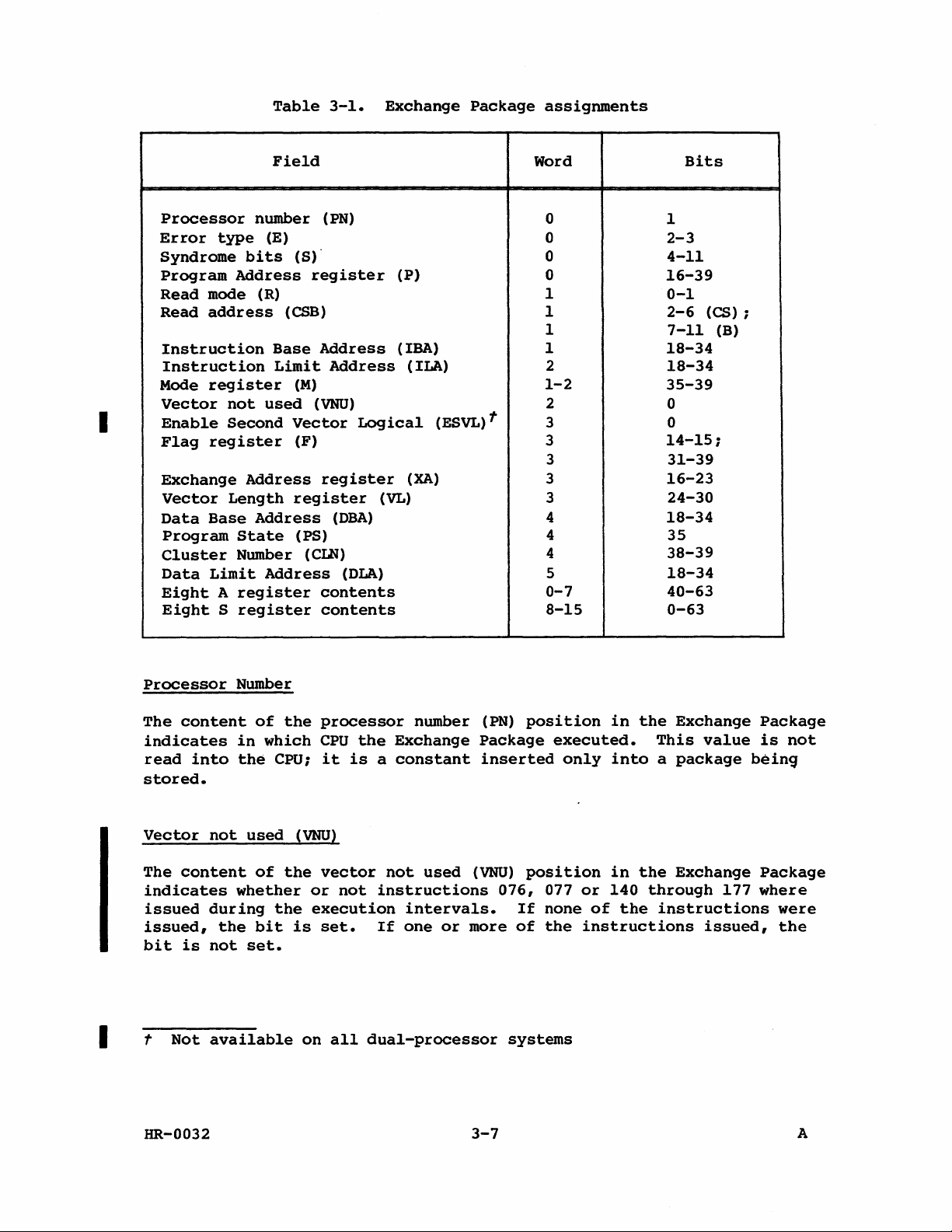
Table
3-1.
Exchange
Package
assignments
I
Field
Processor
Error
Syndrome
Program
Read
Read
Mode
mode
Instruction
Instruction
Vector
Enable
Flag
Exchange
Vector
Data
Program
Cluster
Data
Eight A register
Eight S register
number
type
bits
Address
(R)
address
register
not
Second
register
Address
Length
Base
Address
State
Number
Limit
(E)
(CSB)
Base
Limit
used
Address
(PN)
(S)
register
Address
Address
(M)
(VNU)
Vector
(F)
register
register
(DBA)
(PS)
(CLN)
(DLA)
contents
contents
(P)
(IBA)
(ILA)
Logical
(XA)
(VL)
(ESVL)t
Word
0
0
0
0
1
1
1
1
2
1-2
2
3
3
3
3
3
4
4
4
5
0-7
8-15
Bits
1
2-3
4-11
16-39
0-1
2-6
(CS);
7-11
18-34
18-34
35-39
0
0
14-15;
31-39
16-23
24-30
18-34
35
38-39
18-34
40-63
0-63
(B)
I t
Processor
The
content
indicates
read
stored.
Vector
The
indicates
issued
issued,
bit
HR-0032
into
not
content
during
is
not
Not
available
Number
of
in
the
used
of
whether
the
bit
set.
the
which
CPU;
(VNU)
the
the
is
on
processor
CPU
the
it
is a constant
vector
or
not
execution
set.
all
dual-processor
number
Exchange
not
used
instructions
intervals.
If
one
or
(PN)
Package
inserted
(VNU)
076,
more
of
systems
3-7
position
executed.
only
position
077
If
none
the
in
the
This
into a package
in
the
or
140
through
of
the
instructions
instructions
Exchange
value
Exchange
177
issued,
Package
is
not
bein~
Package
where
were
the
A
Page 64

Enable
Second
Vector
Logical
(ESVL)t
The
Exchange
can
Vector
used;
Memory
Bit
on
memory
consisting
if
I
is
Memory
E
S (Syndrome)
content
be
Logical
only
error
36
uncorrectable
error
bit
36
set
and
error
(Error
of
Package
used.
the
(interrupt
of
is
an
type)
the
enable
indicates
If
set,
unit.
Full
data
memory
data
four
set
and
uncorrectable
data
If
Vector
on
correctable
is
included
fields
correctable
fields
second
whether
instructions
clear,
Logical
error
of
memory
are
The
type
uncorrectable
0,
bits
set
for
set
for a correctable
The 8 syndrome
data
11
additional
error
of
vector
or
the
memory
bit)
information,
described
the
in
in
the
memory
error
of
memory
2
and 3 of
an
uncorrectable
are
Exchange
information.
logical
not
140
through
Second
unit
may
error
the
Exchange
error
below.
or
correctable,
bits
returned
the
Second
Vector
be
bit)
M (mode)
Package.
appears
is
is
detected.
error
the
Exchange
memory
used
in
Package.
(ESVL)
145
Logical
used.
in
encountered
encountered,
memory
in
word
position
Vector
may
select
and
bit
register
Error
the
tt
is
indicated
Package.
error;
error.
detecting
0,
See
section
Logical
the
unit
cannot
38
(interrupt
determine
data,
Exchange
or
if
bit 3 is
a memory
bits
4
2
in
the
unit
Second
be
if
Package
bit
in
word
Bit 2 is
through
for
38
I
R (Read mode)
CSB (Read
t
Not
tt
For
Correctable
HR-0032
address)
available
multiple
on
all
bit
memory
Memory
This
when a memory
1,
bits
The
memory
through
bits
Error
field
bits 0 and 1 of
assume
00
I/O
01
Scalar
10
Vector,
11
Instruction
10-bit
data
11
24
through
dual-processor
errors,
flag
indicates
data
the
(memory
B,
CSS
field
error
(B)
of
the
in
the
3-8
the
error
the
Exchange
following
references
or
T
fetch
contains
occurred.
the
Exchange
20 of
systems
hardware
interrupted
the
read
occurred
values:
or
exchange
Word
address
always
Exchange
mode
the
in
and
Package.
with A or
address
1,
Package
and
sets
progress
is
in
These
S)
where
bits
the
7
contain
can
be
Package.
word
a
A
Page 65

CSB
(Read
(continued)
address)
considered
through 6 of
221
through
l2-column
select
mainframe,
(CS)
mainframe,
field
can
be
as
the
the
Exchange
217
of
of
the
only
the
considered
bank
the
address.
these
address;
high
address.
Package
bits
for
order 3 bits
as
the
chip
Word
1,
contain
For
the
represent
the
6-column
of
select
bits
bits
the
this
(CS).
2
chip
EXCHANGE
Three
Exchange
REGISTERS
special
Address
register.
Exchange
The
a-bit
Address
Exchange
of a l6-word
register
address.
Package
the
absolute
When
the
contents
at
the
Mode
The
currently
and 2 of
must
an
execution
beginning
register
lO-bit
contains
The
active
the
registers
These
Exchange
low-order
begin
address
of
Mode
Exchange
are
(XA)
register,
three
registers
register
Address
Package
the
high-order
bits
on a l6-word
be
interval
the
registers
address
(M)
register
program.
Package
instrumental
(XA)
of
in
the
terminates,
(XA)
contains
The M
the
are
register
loaded
a
bits
the
boundary.
lower
with
the
in
memory.
register
as
follows.
in
the
Mode
(M)
register,
described
specifies
by
an
exchange
of a l2-bit
field
are
always
The
4096 (lO,OOOa)
the
exchange
contents
part
of
bits
the
are
exchange
below.
the
operation.
field
l2-bit
words
sequence
of
the
Exchange
assigned
mechanism:
and
first
specifying
0;
an
limit
of
Exchange
the
Flag
word
address
The
Exchange
requires
memory.
exchanges
Package
Package
in
words
(F)
for
the
the
that
a
1
Word 1
Bit
35
36
37
HR-0032
Description
Waiting
exchanged
the
ClP
for
when a
register.
Floating-point
floating-point
of
the
Floating-point
Bidirectional
and
writes
can
Semaphore
test
Error
error
Memory
operate
(WS)
flag;
and
set
Status
has
Error
Mode
(FPS)
occurred
Mode
(BDM)
concurrently.
3-9
when
set,
instruction
flag;
regardless
flag.
flag;
when
the
was
when
set,
CPU
holding
set,
of
the
block
in
a
state
reads
A
Page 66

Word 1 (continued)
Bit
38
Description
Selected
CPU
39
Interrupt
interrupts
exit.
Word
2
Bit
Description
35 Operand Range
interrupts
36
Correctable
interrupts
37
Floating-point
interrupts
38
Uncorrectable
enables
is
preferred
interrupts
for
External
Monitor
in
monitor
Error
on
operand
Memory
on
correctable
Error
on
floating-point
Memory
Interrupts
for
I/O
Mode
mode
Mode
range
Error
Mode
Error
on
uncorrectable
interrupts.
(EMM)
flag,
except
(lOR)
errors.
Mode
memory
(IFP)
errors.
Mode
(SEI)
flag,
(IeM)
data
flag;
(IUM)
when
PC,
when
flag,
memory
flag,
set,
MCU,
set,
when
errors.
when
flag,
when
enables
I/O,
set,
when
data
set,
and
normal
enables
set,
enables
enables
set,
errors.
this
all
39
The
10
bits
Word
1,
bit
by
using
and 002500
Word
during
002300
2,
bit
the
(enable
interrupt
Word
during
2,
002100
bit
the
(enable
interrupt
Word
1,
bits
instruction
the
CPU
at
altered
be
altered
during
Monitor
except
are
37
Mode
memory
set
selectively
(Bidirectional
instructions
(disable
bidirectional
35 (Operand Range
execution
interval
interrupt
on
operand
37
(Floating-point
execution
range
interval
interrupt
on
floating-point
36 and 37 and word
073iol.
the
the
only
time
of
execution
when
Word
the
(MM)
errors.
002600
on
error).
on
1,
the
exchange.
Exchange
flag,
when
during
Memory
(enable
Mode
bidirectional
Memory
Error
Mode
of a program
operand
Error
range
Mode
for a program
floating-point
error).
2,
bits
bits
35 and 36
The
interval
for
Package
set,
an
exchange
flag)
transfers).
flag)
by
error)
flag),
by
error)
35
and
indicate
remaining
the
is
inhibits
sequence.
can
Memory
can
be
using
and
can
using
and
37
can
Exchange
inactive
all
interrupts
be
set
or
transfers)
set
or
cleared
instructions
002400
be
set
(disable
or
instructions
002200
be
read
the
state
bits
are
not
Package
in
storage.
cleared
cleared
(disable
with
of
and
can
HR-0032
3-10
A
Page 67

Flag
The
the
register
II-bit
currently
contains
Package.
When
one
initiate
stored
program
Before
clear
the
remains
Flag
11
Setting
or
an
along
can
the
monitor
flags
set,
(F)
active
flags
individually
any
more
flags
exchange
with
the
analyze
program
in
another
register
contains
program.
of
these
are
set,
sequence.
rest
of
the
the
11
flags
exchanges
the F register
exchange
occurs
part
This
register
identified
flags
a
The
interrupts
Request
contents
Exchange
for
the
back
area
immediately.
of
within
cause
to
the
of
the
is
located
program
Interrupt
of
the F register
Package.
of
the
package.
Exchange
the
Exchange
signal
The
the
interruption.
package,
Package
in
word 3
execution.
is
sent
are
monitor
it
must
If
any
bit
for
and
to
The F
register
follows.
Word
3
Bit
14
Description
Interrupt
issues
15
Deadlock
issue
31 Programmable
interrupt
O.
32
33
MCU
Floating-point
range
units
Floating-point
computation.
_____________________________________________
34
Operand
made
Data
Range
later
bits
are
assigned
From
instruction
(DL)
on a test
Clock
Internal
001401.
flag;
and
Interrupt
countdown
The programmable
Interrupt
(MCU)
Error
error
and
occurs
the
in
Enable
functional
Range
outside
Limit
Interrupt
in
the
Address
this
Error
boundaries
flag
section.
in
word 3
CPU
(Iep)
set
when
set
counter
clock
flag;
(FPE)
any
all
instruction.
in
is
set
flag;
of
the
Floating-point
units
______ r _____________
(ORE)
flag;
of
(OLA)
is
registers
set.
of
the
flag;
CPUs
(PCI)
flag;
the
programmable
explained
when
the
set
floating-point
Interrupt
are
explained
_
set
when a
the
Data
and
Operand
Exchange
set
when
in a cluster
set
when
later
MIOP
when a
sends
floating-point
data
Base
the
range
Address
Enable
error
Package
the
are
the
clock
in
this
this
functional
flag
in
is
section
reference
Operand
is
as
other
CPU
holding
equals
section.
signal.
set.
4,
is
(DBA)
and
explained
35 Program Range
is
made
(IBA) and
range
HR-0032
outside
Instruction
error
Error
the
is
explained
(PRE)
flag;
boundaries
Limit
Address
later
3-11
of
in
set
when
the
Instruction
(ILA)
this
an
instruction
registers.
section.
Base
fetch
Address
Program
A
Page 68

Bit
Description
36
37
38
39 Normal
Any
flag
if
the
active
set
only
Error
setting
exchange
Cluster
The
contents
and
CPU
the
necessary
flag,
Cluster
SM
registers
does
CLN
Memory
uncorrectable
memory
I/O
1250
Error
(except
if
word
if
an F register
sequence
Number
Number
of
the
not
have
registers
for a deadlock
Error
error
Interrupt
Mbyte
Exit
Exit
the
Exchange
2,
the
is
register
CLN
the
access
in
(ME)
memory
mode
channel
(EEX)
(NEX)
Memory
Package
bit
39
program
are
initiated.
(CLN)
register
CPU
both
register
can
to
interrupt.
flag:
bit
(101)
completes a transfer.
flag:
flag:
Error
of
the M register
is
in
present,
are
access.
any
CPUs
set
error
is
set
flag:
set
set
flag)
is
not
monitor
the
determines
used
SB, ST,
are
also
occurs
set
by
in
flag
to
If
when a
in
when a 6 Mbyte
an
by a normal
can
monitor
mode
determine
the
or
used
correctable
and
the
the M register.
error
be
is
remains
the
CLN
8M
to
exit
set
mode.
O.
and
the
CPU's
register
register.
determine
or
corresponding
channel
instruction
exit
in
which
instruction
the F register
Such
Except
cleared
for
conditions
cluster.
set
is
The
the
or
flags
the
for
and
no
The
of
SB, ST,
0,
then
contents
condition
enable
the
(000).
(004).
only
are
Memory
the
of
I
A
The
of
S
The
of
HR-0032
Program
The
the
concurrently
registers
' word 0
registers
words 8 through
State
content
operating
current
through 7 during
current
register
of
the
I-bit
system
processing
contents
contents
15
to
represent
a
of
all
of
all
during
Program
single
A
registers
exchange.
S
registers
exchange.
State
different
program.
(PS)
3-12
are
are
register
program
stored
stored
is
manipulated
states
in
bits
in
bits 0 through
in
40
the
CPUs
through
by
63
63
A
Page 69

Program
The
contents
program
word
O.
issued
Address
of
instruction
The
instruction
when
this
register
the
Program
not
program
yet
at
begins
Address
issued)
this
location
again.
(P)
are
register
stored
is
the
(address
in
bits
first
of
first
16
through
instruction
39
to
of
be
Memory
Each
data
loaded
program
field
object
that
and
code
beginning
program
reference
addresses
These
field
Exchange
(IBA)
Base
Refer
for
ACTIVE
An
register,
Address
to
an
explanation
EXCHANGE
active
interval
with
it
are
interval
Package
moves from memory
interval
subsequent
registers
program
is
specified
initiated.
are
of
the
to
determine
limits
Package.
(DBA)
the
sUbsection
Exchange
of
time
active
begins
ends
as
exchange
has a designated
by
All
relative
appropriate
to
memory
if
are
contained
The
four
the
Instruction
register,
on
of
the
PACKAGE
Package
when
with
the
the
is
called
an
exchange
Exchange
Exchange
sequence.
the
monitor
memory
to
one
of
field,
is
checked
the
address
registers
Limit
and
Memory
registers.
resides
the
execution
sequence
to
the
operating
Package
field
program
addresses
two
and
against
is
in
four
are:
Address
the
Data
Field
in
the
Package
moves
of
memory
when
contained
base
addresses
limited
the
within
registers
the
(ILA)
Limit
Address
Protection
operating
and
the
interval.
where
the
registers.
back
for
the
object
in
specifying
in
size.
limit
the
bounds
that
are
Instruction
register,
(DLA)
later
registers.
program
An
subject
An
to
memory
instructions
program
the
object
Each
and
object
base
assigned.
saved
Base
Address
the
register.
in
this
section
The
associated
execution
Exchange
execution
in
a
the
in
the
Data
and
is
EXCHANGE
The
Package
SEQUENCE
exchange
from
exchange
operating
a
fixed
sequence
currently
memory
is
destination
block
is
currently
initiated
HR-0032
sequence
memory
sequence
registers
active
used
as
of
the
specified
active
by
deadstart
is
into
moves
the
back
when
all
Exchange
the
source
currently
by
the
Exchange
sequence,
the
vehicle
the
operating
currently
into
memory.
computational
Package
of
has
the
active
content
of
Package.
Interrupt
3-13
for
moving
registers.
active
This
activity
stopped.
inactive
Exchange
the
XA
The
exchange
flag
an
inactive
At
Exchange
swapping
associated
The same
Exchange
Package.
register
sequence
set,
the
same
Package
operation
with
16-word
Package
Location
and
is a part
can
or
program
Exchange
time,
from
is
the
done
the
block
and
the
of
this
of
be
exit.
the
in
of
the
A
Page 70

Exchange
The
deadstart
and
also
exchange
The
inactive
registers
Package
deadstart
discards
CPUs
with
initiated
forces
using
Exchange
and
swapped
operation.
the
old
an
interprocessor
by
sequence
an
interrupt
memory
initiates
to
address 0 is
Exchange
deadstart
forces
address 0 as
Package
a
program
New
data
Package
sequence
the
in
one
at
largely
entered
interrupt.
XA
register
cpu.
the
address 0 then
using
in
preparation
These
location
these
indeterminate
at
these
content
two
of
moves
parameters.
storage
for
to 0 for
actions
the
into
because
starting
cause
Exchange
the
The Exchange
of
addresses
subsequent
both
operating
CPUs
an
Package.
the
then
I
When
exchanges
panel
Exchange
An
flags
Interrupt
Exchange
Two
the
determined
instructions
The two
non-monitor
exchange
termination
same
instruction
selects
initiated
exchange
in
the F register.
initiated
program
instruction
000
004
exits
back
as
for a normal
001401
to
address 0 in
which
sequence
signal
exit
by which
are:
E~
EX
enable a program
(object)
to
of
an
CPU
by
can
to
initiate
by
instructions
execution
of
program
the
monitor
object
exit.
(IP)
memory.
is
deadstarted
Interrupt
be
initiated
Setting
program
is
the
two
program.
is
issued
(A
flag
of
an
exchange
exit
initiate
the
same
flags
Error
Normal
usually
program.
to
exit
request
The
in
switch
first.)
set
by
one
an
in
is
exit
uses
The
exchange
the
first
on
setting
or
more
sequence.
exchange
either
set
in
its
own
the
normal
error
CPU,
the
mainframe's
anyone
flags
sequence.
case;
the F register.
termination.
exit
address
the
of
causes a Request
the
difference
exit
instruction
allows
selected
second
control
the
Interrupt
Timing
The two
A
for
CPU
of
is
to
abnormal
is
the
Each
set
executes
program
The
by
register
HR-0032
instruction
if
inactive
monitor
setting
the
currently
Exchange
in
monitor
termination
program
the
and
then
has a flag
active
Package
mode.
cause.
selects
address
of
executing a normal
in
Exchange
called
Flags
an
the
the F register.
Package
in
this
case
are
checked
inactive
inactive
Exchange
Exchange
exit
3-14
The
is
not
is
normally
for
evaluation
Package
Package
instruction.
appropriate
in
monitor
one
of
for
in
the
flag
mode. The
that
the
activation
XA
is
A
Page 71

Exchange
The
following
cases
for
sequence
are
an
exchange
issue
hold
conditions
issue
conditions,
sequence.
execution
time,
and
special
Hold
conditions:
• NIP
•
S,
Execution
For
32
fetch
For
16
fetch
Special
cases:
If a test
CIP
and
(Waiting
test
EXCHANGE
Each
l6-word
deadstart.
words
of
program's
and
monitor
for
the
programs
addresses
so
that
The
it
defined
Exchange
Exchange
in a CPU
Packages
software
register
V,
or A registers
contains
time:
banks,
40
operation
banks,
42
operation
and
set
NIP
registers
for
Semaphore)
and
set
instruction.
PACKAGE
MANAGEMENT
Exchange
The
defined
memory. The
Exchange
tasks.
Package.
Non-monitor
they
for
the
programs.
can
access
field
Packages
Package.
and
which
controlled
allows
other
memory
can
Since
be
situations.
CPs;
consists
(16
CPs).
CPs;
consists
(18
CPs).
instruction
are
Package
area
package
represent
all
of
the
than
no
transfers
used
a
valid
busy
cleared
flag
resides
must
at
Other
packages
as
Only
memory,
monitor
its
interlock
in
by
another
instruction
of
an
exchange
of
an
exchange
is
holding
and
the
set
and
the P register
in
an
lie
within
address 0 is
packages
lie
determined
the
monitor
including
program
own
when
it
exists
another
CPU
CPU,
should
sequence
sequence
in
the
CIP
exchange
area
defined
the
lower
the
deadstart
provide
for
outside
by
the
program
Exchange
to
define
is
the
currently
between
modification
be
avoided,
(24 CPs)
(24 CPs)
register,
occurs
pointing
during
4096
(10,0008)
monitor
object
of
the
field
base
and
has a field
Package
or
alter
an
exchange
of
except
and
and
both
with
to
the
the
system
programs
lengths
limit
defined
areas.
all
active
sequence
Exchange
under
a
a
WS
Proper
management
program
it.
The
exchanged
HR-0032
always
exchange
into
of
Exchange
exchanges
ensures
its
proper
Packages
back
that
to
the
Exchange
the
monitor
program
Package.
3-15
dictates
information
that a non-monitor
program
that
is
exchanged
always
to
A
Page 72

For
example,
following
execution
exits
so,
by
program A sets
program
execute.
Package
The
program
same
to
exchange
B's
time,
Exchange
When
To
the
illustrate
executing,
the
deadstart.
interval
issuing
(B)
Exchange
Program A
point
sequence
Exchange
the
Package
exchange
the
an
Interrupt
program B cannot
B's
Program
program
execution
parameters
A's
parameters
interval
monitor
since
a
normal
the
Package
sets
back
to
Package
exchange
area
with
is
complete,
exchange
alter
exchange
program
No
interrupts
it
exit
contents
the
to
program
is
(A)
in
monitor
instruction
of
so
that
exchange
A.
program B causes
to
be
address
all
in
other
program B begins
sequence,
flag
the
exchange
held
sets
XA
register,
in
back
initiating
back
program
into
begins
(except
mode. Program A
(004).
the
XA
register
program B is
address
the
entered
the
XA
in
register
program
assume
the
into
B's
the
its
package
operating
an
execution
memory)
However,
to
the
in
program
exchange
the
XA
goes
parameters
its
that
while
an
exchange
exit
is
Exchange
area
interval
can
terminate
voluntarily
point
next
program
B's
address
register.
to
program
for
execution
program B is
sequence.
back
to
Package
during
registers.
before
to
the
Exchange
from
At
program
interval.
program
area;
the
its
doing
user
to
the
B's
A.
Since
A.
Program
the
exchange
processor
Exchange
clears
normal
C
can
the
exit
execute
Further
COS
EXEC/STP/CSP
MEMORY
At
for
FIELD
execution
instructions
program
begin
can
The
All
one
at
continue
fields
memory
of
the
field.
an
absolute
reference
determine
A, upon
resuming
and
into
execution.
Package
interrupt
instruction
in
information
PROTECTION
time
when
any
can
the
word
to
another
overlap.
addresses
two
base
An
object
address
to
memory
if
the
sets
for
the
the
and
monitor
on Exchange
Internal
each
object
and
data.
object
program
address
address
contained
addresses
program
lower
is
checked
address
execution,
XA
register
To
do
interrupt
initiates
(004).
mode
or
Reference
program
The
that
is a multiple
in
specifying
cannot
than
that
against
is
within
determines
to
this,
program A sets
processing
execution
Depending
in
user
Package
management
Manual,
has a designated
field
is
that
read
loaded
is
the
or
limits
one
object
base
the
the
bounds
call
the
program
of
on
the
mode.
publication
are
and
initiated.
of
less
program
the
beginning
alter
any
address.
limit
assigned.
an
interrupt
proper
interrupt
XA
to
(C).
program C by
operating
is
contained
SM-0040.
field
specified
The
32
(that
is,
than a multiple
code
are
of
the
memory
Each
and
base
location
object
addresses
A memory
has
caused
point
Program A
executing
task,
program
in
of
memory
by
the
monitor
fields
408) and
of
relative
appropriate
program
read
to
the
32.
with
to
the
a
can
to
HR-0032
3-16
A
Page 73

reference
zero
value
the
assigned
beyond
is
transferred
field
the
limits
assigned
from memory. A memory
is
field
allowed
limits
to
issues
issue,
write
but
and
completes,
no
write
reference
occurs.
but
a
beyond
Field
Address
Data
register.
limits
limits
Base
are
(IBA)
Address
These
described
INSTRUCTION
The
Instruction
userls
if
than
register
instruction
the
absolute
or
equal
of
instruction
The
contents
bits
of a 22-bit
assumed
Absolute
the
lBA
to
be 0 because
memory
register
twenty-second
A
reference
can
only
the
occur
memory
capacity
are
register,
BASE
Base
address
to
the
program
buffer
of
the
addresses
power.
to
an
through
contained
the
(DBA)
four
ADDRESS
register,
registers
in
the
REGISTER
Address
field.
at
the
contents
executing.
fetch
memory
IBA
time
register
address.
of
to
the P register
absolute
a jump
of
the
in
four
Instruction
and
following
(IBA)
An
instruction
which
of
by
the
number
for
an
address
or
machine.
registers:
Limit
and
the
flags
paragraphs.
register
the
instruction
the
current
This
determination
the
CPU.
are
interpreted
The
low-order 5 bits
of
banks,
instruction
(high-order
less
branch
than
instruction
the
Address
Data
Limit
associated
holds
can
only
is
Exchange
as
32
fetch
22
the
address
Instruction
(ILA)
Address
with
the
base
be
executed
located
Package
is
the
high-order
of
(decimal)
are
formed
bits)
modulo two
defined
to
an
Base
register,
(DLA)
the
field
address
by
is
greater
IBA
made
the
at
address
banks.
by
address
of
the
17
adding
to
by
IBA
beyond
the
the
CPU
are
the
INSTRUCTION
The
Instruction
the
userls
absolute
current
address
Exchange
determination
The
contents
bits
of a 22-bit
assumed
largest
[(ILA) x 2
If
by
the
the
generates
to
absolute
the
final
CPU
currently
5
a
HR-0032
LDMIT
ADDRESS
Limit
field.
An
where
Package
is
made
of
the
lLA
memory
be 0 because
address
] -
1.
absolute
does
not
fall
executing
program
range
REGISTER
Address
instruction
it
is
located
lLA
register
at
instruction
register
address.
of
the
that
address
can
of
between
Exchange
error
(ILA)
can
are
The
number
be
the
the
Package
interrupt.
3-17
register
only
is
of
buffer
less
the
holds
be
executed
than
program
fetch
interpreted
low-order 5 bits
of
banks,
executed
32
by a program
instruction
range
of
IBA
addresses
and
the
the
executing.
time
as
the
(decimal)
buffer
lLA
registers,
limit
by
the
contents
by
the
high-order
of
the
is
fetch
contained
address
CPU
if
of
the
This
CPU.
address
banks.
defined
as
computed
within
the
of
the
17
are
The
by
CPU
A
Page 74

DATA
BASE
The
Data
data
field.
absolute
the
contents
executing.
stored
The
bits
by
contents
of a 22-bit
register
formed
two
to
by
the
ADDRESS
Base
An
address
of
This
the
of
REGISTER
Address
operand
where
the
determination
CPU.
the
memory
are
assumed
adding
the
twenty-second
(DBA)
can
the
current
DBA
register
address.
to
be
DBA
register
power.
register
only
be
operand
Exchange
is
are
O.
Absolute
holds
fetched
is
located
Package
made
interpreted
The
low-order
to
the
the
each
memory
modified
base
or
stored
is
DBA
time
5
addresses
address
by
greater
register
an
operand
as
the
bits
operand
of
the
CPU
than
of
the
is
high-order
of
the
for
operands
address
the
if
or
equal
program
fetched
DBA
modulo
user's
the
to
or
17
are
DATA
contents
The
the
CPU
LLMIT
Data
user's
if
the
Limit
of
executing.
stored
The
bits
register
by
contents
of a 22-bit
are
referenced
If
the
final
not
fall
between
executing
operand
PROGRAM
The
(address)
RANGE
Program
boundaries
out-of-range
a
branch
the
or
limits.
terminates
the
Program
aborting
the
ADDRESS
Address
data
field.
absolute
the
current
This
determination
the
CPU.
of
the
memory
assumed
for
data
absolute
the
Exchange
ERROR
Range
of
the
memory
jump
instruction
The
Program
program
Range
user
REGISTER
(DLA)
An
address
Exchange
DLA
register
address.
to
be
by a program
address
range
Package
range
Error
IBA
error
flag
and
ILA
reference
Range
execution.
Error
flag
program.
register
operand
where
is
O.
The
of
of
addresses
DBA
and
interrupt.
sets
registers
can
calling
Error
The
and
holds
can
only
the
operand
Package
made
are
The
DLA
each
interpreted
low-order
largest
is
defined
the
operand
contained
DLA
registers,
if
a memory
is
occur
in a non-monitor
for a program
flag
monitor
takes
appropriate
the
be
is
register
time
absolute
by
as
reference
for
an
causes
program
(upper)
fetched
located
an
operand
as
the
5
bits
address
[(DLA)
computed
within
the
instruction
address
an
error
checks
action,
limit
or
stored
is
of
the
high-order
of
the
x 25] -
by
the
CPU
generates
outside
mode
above
condition
the
perhaps
address
by
less
than
program
is
fetched
DLA
that
can
1.
the
CPU
currently
the
fetch.
program
or
state
of
the
the
or
17
be
does
an
An
on
below
that
of
HR-0032
3-18
A
Page 75

OPERAND RANGE ERROR
The
Operand
set
and
registers
register
Range
program
Range
Error
Error
Range
a memory
is
called
and
the
flag
execution.
flag
reference
Operand
causes
and
program.
Error
to
The
takes
flag
outside
read
or
Range
an
error
monitor
appropriate
sets
write
Interrupt
condition
program
if
the
the
an
Operand
boundaries
operand
Error
flag
that
checks
action,
the
perhaps
Range
for
of
the
an
is
Error
A,
set.
terminates
state
aborting
DBA
B,
the
of
Mode
and
S,
The
the
flag
DLA
T,
or
Operand
user
Operand
the
user
is
V
PROGRAMMABLE
The
programmable
intervals.
periodic
interrupt.
nanoseconds
shorter
overhead
than
involved
programmable
Interrupt
Countdown (ICD)
INSTRUCTIONS
Four
monitor
0014j4
001405
001406 ECI
CLOCK
clock
Intervals
to
approximately
100
microseconds
in
clock
mode
PCI
are
instructions
Sj
CCI
can
be
selected
The
clock
40.8
processing
the
Interrupt
counter,
Enter
Clear
request
Enable
request
used
under
frequency
seconds
are
not
the
support
(sj)
to
accurately
monitor
is
are
practical
interrupt.
Interval
and
four
the
Interrupt
the
programmable
the
programmable
measure
program
105
Mhz.
control
possible.
due
to
Supporting
(II)
register,
monitor
mode
programmable
Interval
clock
clock
the
Intervals
Intervals
the
monitor
the
instructions.
clock:
(II)
register
interrupt
interrupt
duration
generate
from
the
of
a
9.5
with
001407
INTERRUPT
The
32-bit
value
clock
equal
interrupt
low-order
counter
when
HR-0032
DCI
INTERVAL
Interrupt
to
the
requests.
32
bits
of
instruction
REGISTER
Interval
number
the
of
Sj
0014j4
Disable
request
(II)
CPs
The
interrupt
register
register
that
is
executed.
3-19
the
programmable
can
are
to
interval
into
the
be
elapse
II
register
clock
loaded
between
is
transferred
interrupt
with a binary
programmable
from
and
the
ICD
the
A
Page 76

This
counter
request.
instruction
value
each
is
time
The
0014j4.
held
content
in
the
the
II
counter
of
the
register
reaches 0 and
II
register
and
is
transferred
generates
is
changed
an
only
to
the
interrupt
by
another
ICD
INTERRUPT
The
32-bit
the
II
continuously
of
the
request
repeats
interrupt
When
programmable
mode.
CLEAR
Following a program
the
until
programmable
interrupt
request
interrupt
COUNTDOWN
Interrupt
register
counter
and
the
request
programmable
a
clear
request
set
PROGRAMMABLE
request
when
but
counts
is
samples
countdown
at
programmable
clock
clock
causes
in
monitor
can
COUNTER
Countdown (ICD)
instruction
down,
o.
The
ICD
the
interval
to
zero
regular
clock
interrupt
interrupt
mode
CLOCK
interrupt
be
interrupt
clock
an
interrupt
is
INTERRUPT
cleared
counter
0014j4
decrementing
sets
cycle,
intervals
request
request
interval,
the
value
interrupt
held
REQUEST
by
setting
request
can
is
only
until
executing
is
preset
is
executed.
by 1
each
programmable
held
determined
in
the
is
request
be
set
executed.
when
the
system
an
active
instruction
the
programmable
by
set,
only
not
programmable
to
the
This
counter
CP
until
clock
II
is
after
A
programmable
in
switches
interrupt
register.
the
interval
it
remains
executed.
the
monitor
001405.
contents
runs
the
content
The
clock
value.
set
A
enable
clock
mode. A
to
user
clock
of
ICD
Following
the
programmable
001407.
PERFORMANCE
The
system
hardware
performance.
instructions
references,
Appendix C
HR-0032
any
MONITOR
contains
related
etc.
for
deadstart,
clock
events
The
events
issued,
and
complete
interrupt
a
set
that
hold
are
information
the
monitor
of
eight
can
that
can
issue
selected
program
by
issuing
performance
be
used
be
tracked
conditions,
through
on
performance
3-20
should
instructions
counters
to
indicate
are
the
number
instruction
ensure
to
relative
the
number
of
0015jO.
monitoring.
the
001405
track
of
fetches,
state
and
certain
specific
Refer
of
to
A
Page 77

DEADSTART
The
deadstart
mainframe
whenever
All
registers
memory
following
I/O
Subsystem.
1.
2.
4.
The
Master
critical
clears
activates
inactive.
monitor
memory.
sequence
program
the
should
Turn
Turn
3.
Turn
Load memory
5.
Turn
control
the
program.
Turning
to
in
SEQUENCE
sequence
after
sequence
the
power
operating
in
be
on
Master
on
I/O
off
off
Clear
input
MCU
The
I/O
read
CPU
0 (PN=O).
the
considered
I/O
Master
signal
latches
Channel
input
The Exchange
off
this
of
operations
has
been
system
machine,
of
operations
Clear
Clear
via
Subsystem
signal.
Clear
I/O
Clear
halts
to
Address
channel.
the
Master
package
signal.
starts
turned
is
all
invalid
to
signal.
Subsystem.
signal.
all
predetermined
then
Package
Clear
and
off
to
be
control
after
begin
internal
register
All
other
loads
signal
to
begin
reinitialized
must
a
program
and
then
latches,
power
the
program
computation
states.
of
the
input
an
initial
be
located
initiates
execution
turned
and
has
been
The
MCU
channels
Exchange
running
on
in
the
all
words
turned
is
initiated
and
forces
I/O
Clear
channel
at
address 0 in
the
exchange
of
the
in
the
again
mainframe.
and
remain
Package
monitor
or
in
on.
by
signal
The
the
and
I
CPU
1 (PN=l)
(IP)
is
Because
Exchange
Package
can
be
started
panel.)
system.
remains
issued
the
Package
at
Subsequent
in
CPU
exchange
at
address 0 before
first
in a master-cleared
O.
Then
of
CPU 0 overwrites
address
by
using a switch
actions
CPU 1 exchanges
0,
CPU 0 must
allowing
are
dictated
other
on
state
the
reinitialize
the
by
until
to
contents
CPUs
to
mainframe's
the
design
instruction
address 0 in
of
the
the
Exchange
start.
of
(Either
control
the
001401
memory_
inactive
CPU
operating
HR-0032
3-21
A
Page 78

Page 79

CPU
INTRODUCTION
C·OMP.UT
ATION
SECTION
4
I
Each
computation
Address
performed
A
a
of
or
The
instruction
processing
units
functional
set
dedicated
functional
Address
to
distributed
controlling
registers
units
address
Central
CPU
associated
addresses
integer
vector
series
results.
operand
main
dedicated
of
64-element
information
address
generate
registers.
Memory
processing
arithmetic
of
contains
section
with
and
on
is
pair,
advantage
has
units
solely
units
registers.
can
three
indexes
data.
an
ordered
elements
Scalar
start-up
two
solely
to
various
the
scalar,
also
address
from
an
identical,
consists
types
operates
and
functional
set
repeating
processing
and
produces a single
of
vector
time
levels
to
shared
registers
to
vector
supporting
flows
Information
parts
supply
and
Address
the
of
on
has
of
for
of
scalar
with
of
applications,
both
from
vector,
operands
index
information
address
independent
of
operating
processing:
internal
two
levels
units.
elements.
the
same
starts
over
vector
of
scalar
all
but
64-bit
processing,
64
bits
scalar
Central
the
and
information
registers.
in
to
registers
control
of
Scalar
A
vector
function
an
instruction,
result.
processing
the
first
scalar
operations.
the
control
I/O
two
registers,
each,
and
and
vector
Memory
address
network
operations.
integer
can
also
computation
address,
information
24-bit
and
vector
instruction
and
operand.
and
three
vector
fourt functional
three
or
and
floating-point
operations.
from
registers
functional
return
be
section.
and
functional
scalar,
registers
processing
producing
handles
is
eliminating
four
floating-point
processing
control
for
use
The
address
the
transmitted
and
such
and
operates
a
one
Scalar
functional
units
registers
is
in
units.
result
to
A
units
vector.
as
two
are
series
operand
has
The
to
the
on
a
I
Data
and
units
functional
depending
can
vector
t
HR-0032
flow
from
to
provide
functional
Five
Vector
in a computation
registers
registers
units.
on
the
one
vector
Logical
to
and
Data
processing
required
units.
functional
unit.
section
functional
from
registers
flows
mode.
operand
units
units.
along
for
are
is
from
to
either
An
exception
vector
available
4-1
Central
Results
Central
the
operations
on
Memory
flow
Memory
scalar
is
that
systems
to
registers
from
functional
or
back
or
vector
scalar
performed
with a Second
registers
to
path
in
the
A
Page 80

Integer
or
computation
mode.
Floating-point
floating-point
section.
arithmetic
Integer
quantities
operations
arithmetic
have
is
signed
are
performed
performed
magnitude
in
in
twos
complement
representation.
the
Floating-point
multiplication,
approximation
using a multiple
results
Integer
subtraction,
subtraction
integer
multiply
(I-bit
or
fixed-point
and
operations
multiply
operation
floating-point
products.
full
64-bit
operation
These
product.
is
accomplished
floating-point
The
instruction
and
exclusive
operations
produce
most
operations
integer
Full
in
in
indexing
either
either
performed
allow
64-bit
product
scalar
mode.
on
rows
operations.
instructions
and
reciprocal
instructions
instruction
sign,
IS-bit
integer
operation
is
done
multiply
partial
No
hardware.
set
includes
OR
and
for a mask-controlled
the
manipulation
results.
are
implemented
is a scalar
capability
or
vector
Indexing
or
the
provide
approximation.
provide
for a floating-point
sequence.
exponent,
operations
are
multiplication.
produce
either
produces a 24-bit
through a software
functional
products
integer
unit
are
divide
through a software
Boolean
of
With
the
in
exception
vector
instruction
allows
the
programmer
modes. The
allows
diagonal
matrix
as
for
addition,
These
and
48-bit
integer
Integer
24-bit
to
generate
then
shifted
instruction
operations
merge
either
of
and
designed
index
operations
well
as
subtraction,
The
reciprocal
instructions
normalized
addition,
addition
or
64-bit
result.
algorithm
multiple
and
is
algorithm
for
OR,
operation.
64-bit
or
24-bit
scalar
to
can
instructions.
for
index
index
be
positive
in
conventional
divide
produce
coefficient).
integer
and
results.
A
64-bit
using
the
partial
merged
to
providedl
using
AND,
equivalence,
Shift
128-bit
integer
operands
arithmetic,
calculation.
throughout
or
vector
mode
column-oriented
operation
64-bit
An
integer
form
the
the
The
memory
negative
to
be
to
Population
and
operations.
Characteristics
•
Integer
•
Twos
•
Signed
•
Address,
•
Thirteen
•
Eight
•
Sixty-four
•
Eight
•
Sixty-four
•
Eight
HR-0032
parity
An
additional
of a CPU
and
floating-point
complement
magnitude
scalar,
functional
24-bit
address
24-bit
64-bit
scalar
64-bit
64-element
counts
are
scalar
computation
integer
floating-point
and
vector
units
(A)
intermediate
(S)
intermediate
vector
provided
operation
section
arithmetic
arithmetic
processing
registers
address
registers
scalar
(V)
registers,
4-2
for
both
is
are
arithmetic
modes
(B)
(T)
64
vector
the
leading
summarized
registers
registers
bits
per
and
scalar
zero
below.
element
count.
A
Page 81

OPERATING
REGISTERS
Operating
the
speed
functional
operands
deliver
be
used
A
CPU
primary
this
manual
primary
For
the A and S registers,
which
the
primary
registers
instructions
reduced.
referred
registers
ADDRESS
registers,
of
the
units.
per
clock
results
concurrently.
has
three
sets
of
as
because
is
not
accessible
registers.
and
Central
required
The
intermediate
to
as B registers.
are
referred
REGISTERS
a
system
A
single
period
at a rate
primary
registers
A,
S,
and
functional
primary
by
satisfying
functional
(CP)
of
one
and
two
are
V,
respectively.
units
an
to
the
Block
Memory
for
so
scalar
registers
The
to
as T registers.
programmable
heavy
unit
to
perform
per
CP.
intermediate
address,
can
scalar,
access
intermediate
functional
transfers
that
and
are
the
address
that
intermediate
resource
demands
can
the
necessary
Multiple
sets
These
them
level
units
possible
number
operands
support
registers
of a CPU,
for
data
require
one
functions
functional
of
registers.
and
vector,
registers
directly.
of
registers
but
acts
between
of
memory
is
the A registers
that
enhance
made
to
by
three
and
units
The
designated
are
considered
exists
as a buffer
these
reference
greatly
are
support
the
can
can
in
for
S
Figure
4-1
processing.
registers
A
REGISTERS
Eight
24-bit A registers
primarily
registers.
channel
zeros
for
address
The
I/O
count.
scalar
increment
address
performing
registers
Data
placed
is
moved
in B registers.
illustrates
The two
types
and B registers
used
as
address
They
provide
operations
In
address
memory
references
for
vector
functional
24-bit
and
integer
by
delivering
directly
registers
of
and
and
address
are
serve a variety
registers
values
and
for
receive
applications,
and
provide
memory
units
support
arithmetic
the
results
between
Placing
Central
data
functional
registers
described
of
for
memory
shift
values
counts,
of
A
registers
both a base
references.
address
on
operands
to A registers.
Memory
in B registers
in
units
are
the
used
designated
following
applications
references
loop
population
index
address
and
index
obtained
and A registers
allows
for
A
paragraphs.
but
are
and
as
control,
count
the
and
base
and
generation
from
A
or
buffering
address
index
and
leading
address
an
by
is
of
HR-0032
4-3
A
Page 82

Exchange
control
Shifts
Multiply
Add
Ai
SBj
Ai.~----------,
Ak~-----------4~~~----~
r----=--~--++-+_-t__-
r------~--~-+___<~~-
L--UI4p--------+-+----1I...--
~+=======~~=========-J
....
Ai
-+-----I
Ak
...
..
Address
functional
units
the
data
transferred
(SB)
registers.
The
Vector
set
by
transmitting
can
also
under
When
Vector
an
issued
reservation
instructions
HR-0032
Figure
4-1.
Address
between A registers
between
Length
be
transmitted
Control
A and S
(VL)
register
a
value
Registers
to
instruction
is
set
for
that
that
use
the
registers
and
Central
registers
and Exchange
to
them from an A
an A
register.
later
delivers
register.
register
and
in
new
until
4-4
and
Memory.
between
(The
this
data
The
reservation
the
functional
Data
A and Shared
Address
register.
VL
register
section.)
to
an A
new
data
units
can
also
(XA)
register
The
register,
prevents
is
delivered.
be
Address
VL
register
is
described
a
issue
are
of
A
Page 83

In
this
manual,
letter
reference
j,
The
in
A
followed
A
or k designator
only
the
register
following
the A registers
by
registers
as
implicitly
instructions:
a number
by
specifying
described
are
individually
ranging
the
in
section
referenced
referred
from 0 through
register
5.
is
the
number
AO
register
to
7.
Instructions
as
by
the
h,
as
illustrated
the
i,
I
OlOiikm
Ollijkm
012iikm
013iJKm
034ijk
035ijk
036ijk
037ijk
l76iok
l770jk
JAZ
JAN
JAP
JAM
exp
exp
exp
exp
Bjk,Ai
,AO
Bjk,Ai
TJK,Ai
,AO
Tjk,Ai
vi
,AO,Ak
,AO,Ak
,AO
,AO
Vj
Branch
Branch
Branch
includes
Branch
Read (Ai)
from
Store
jk
Read (Ai)
(AO)
Store
jk
Read
incremented
Store
incremented
to
to
to
to
(AO)
(Ai) words
to
(AO)
(Ai) words
to
(AO)
(VL)
(VL)
iJKm
iJKm
iJKm
(AO)=O
iJKm
words
words
words
if
if
if
if
to B register
at B register
to T register
at T register
to
by
(Ak)
words from
by
(Ak)
(AO)=O
(AO)~O
(AO)
is
positive,
(AO)
is
negative
Vi
from
Vj
to
(AO)
(AO)
jk
jk
from
Section 5 of
registers
B
REGISTERS
A
computation
intermediate
data
unnecessary
Memory. Examples
and
HR-0032
to
dimensions.
this
by
instructions.
storage
be
referenced
to
section
retain
manual
contains
for
repeatedly
the
of
uses
contains
the A registers.
data
are
additional
sixty-four
over a sufficiently
in
either
loop
counts,
4-5
information
24-bit B registers
Typically,
A
registers
variable
B
long
or
array
on
the
used
registers
span,
in
Central
base
use
of
as
contain
making
addresses,
A
A
it
Page 84

Transfer
1 CP. A
Memory
made
on
of a value
block
at
the
all
B
between
of B registers
maximum
registers
rate
during
an A register
can
be
of
one
24-bit
block
N~E
and
transferred
value
transfers
a B
per
to
register
to
or
from
CP. A
and
reservation
from B registers.
requires
Central
only
is
Other
block
Central
In
this
manual, B registers
followed
by a 2-digit
Instructions
the
JK
designator
The
only B register
execution
to
the
specified
of
next
by
conventionally
called
routine
executes
routine
wishes
instruction
is a branch
into
the P register
executed.
instructions
of B registers
Memory.
reference
as
implicitly
the
return
instruction
ijkm
occurs.
saves
to
initiate
to
return
to
(Bjk),
as
can
are
octal
B
number
registers
described
jump
parcel
Upon
(BOO)
so
return
to
its
0050JK.
causes
the
address
issue
is
being
on
transferred
individually
ranging
by
specifying
in
section
referenced
instruction,
address
(P)
receiving
that
the
BOO
jumps
caller,
of
it
Conventionally,
the
address
of
the
the
CRAY
referred
from
00
the B register
5.
is
the
BOO
007ijkm,
and a branch
control,
register
its
own.
restores
this
saved
next
in
instruction
X-MP
while
to
or
from
to
by
through
register.
register
to
the
called
is
available
When a called
the
saved
instruction,
Bjk
to
be
a
the
77.
BOO
an
address
routine
address
entered
parcel
letter
number
On
is
set
for
which
to
B
in
the
and
be
SCALAR
Figure
REGISTERS
4-2
illustrates
processing.
and T registers
S
REGISTERS
Eight
serving
arithmetic
both
HR-0032
64-bit
as
integer
the
and
The two
and
S
registers
source
logical
and
floating-point
registers
types
are
described
are
and
destination
instructions.
of
scalar
the
and
functional
registers
in
the
principal
for
Scalar
arithmetic
4-6
units
are
following
scalar
operands
functional
operations.
used
designated
paragraphs.
registers
executing
units
for
scalar
S
registers
for a CPU
scalar
perform
A
Page 85

Memory
Scalar
V
registers
Floating-paint
VM
PCl.
Status
functional
Add
units
S
registers
transmissions
register
are
Figure
can
of
also
4-2.
furnish
data
possible.
_____
...
Scalar
one
operand
between
r--------f-+--+--+--~~
J--L.
.....
-------1H+-+--...---I
registers
in
vector
an S register
and
functional
instructions.
and
an
element
Ai
Ak
units
Single-word
of
Scalar
funct iona 1
units
a V
Data
placed
is
moved
in T registers.
operands
transferred
registers,
Other
Mask
uses
(VM)
Interrupt
HR-0032
directly
between S registers
between
This
intermediate
and
between A and S registers,
and
between
of
the S registers
register
Interval
S and Semaphore
or
the
Real-time
(II)
register.
Central
Central
are
the
Memory
step
Memory.
between S and
(SM)
setting
Clock
(RTC)
4-7
and S registers
allows
buffering
Data
Shared
registers.
or
reading
register
is
also
of
or
or
of
Scalar
the
Vector
setting
is
scalar
(ST)
the
A
Page 86

When
letter
an
issuing
reservation
that
read
In
this
manual,
S
reference
is
the
followed
S
registers
or k designator
The
in
only
the
register
following
instruction
set
for
that
register
until
the S registers
by
a number
by
as
described
implicitly
instructions.
delivers
register
the
are
ranging
specifying
in
section
referenced
new
preventing
new
data
individually
from 0 through
the
data
is
delivered.
register
5.
is
the
to
an S register,
issue
of
referred
7.
number
SO
register
instructions
to
by
Instructions
as
the
i,
as
illustrated
a
the
j,
Ol4iJKm JSZ exp
Ol5ijkm
Ol6iJKm
Ol7iJKm
052ijk
053ijk
The
8-bit
•
• Program
•
•
•
•
•
Instruction
register.
Status
Processor
Cluster
Floating-point
Floating-point
Bidirectional
Operand
073
JSN exp
JSP
JSM
SO
SO
exp
exp
si<exp
Si>e~p
register
Number
State
Number
Memory
Range
Interrupts
sends
provides
(PN)
(PS)
(CN)
Interrupts
Error
Enabled
the
contents
Branch
Branch
Branch
includes
Branch
Shift
Shift
Enabled
(FPE)
Enabled
to
to
to
to
(Si)
(Si)
the
(BDM)
of
iJKm
ijkm
iJKm
(SO)=O
iJKm
left
right
status
(IFP)
(lOR)
the
Status
if
(SO)=O
if
(SO)~O
if
(SO)
if
(SO)
jk
places
jk
places
of
register
is
is
the
positive,
negative
to
SO
to
SO
following
to
an
flags:
S
Section 5 of
registers
T
REGISTERS
The
computation
by
intermediate
and S registers
a
value
HR-0032
between
this
manual
instructions.
section
storage
for
and
between T registers
a T
register
has
additional
has
sixty-four
the S registers.
and
an S register
4-8
information
64-bit
T
Data
and
Central
requires
on
registers
is
transferred
Memory.
the
only
use
used
Transfer
1 CP.
of
S
as
between
T
of
A
Page 87

T
registers
instructions.
CP. A
and
reservation
from T registers.
reference
Block
Central
transfers
is
made
on
Memory
occur
all
T
NOTE
through
block
at a maximum
registers
during
read
rate
and
of
block
block
one
word
transfers
write
per
to
In
this
manual, T registers
octal
number
registers
described
VECTOR
Figure
REGISTERS
4-3
operations.
in
the
following
V
REGISTERS
The
major
with
data
64
elements.
is
grouped
quantity
rows
or
columns
efficiency
vector.
successive
operands
and
the
result
Successive
performed,
V
register.
operations
content
of
Other
block
Central
instructions
of T registers
Memory.
ranging
by
specifying
in
section
illustrates
Vector
paragraphs.
computational
into
can
be
treated
of a matrix
is
achieved
Vector
V
are
instructions
register
obtained
is
delivered
elements
the
result
The
vector
performed
the
VL
register.
from 00
the
5.
the
registers
registers
Each V
successive
as a vector.
by
elements.
from
are
provided
is
operation
by
the
can
is
are
through
octal
registers
and
register
or
elements
identically
provide
the
first
to
the
delivered
instruction
issue
on
being
referred
77.
number
and
Vector
of a CPU
element
elements
Examples
processing
for
A
vector
element
first
each
CP
to
successive
continues
the
CRAY
transferred
to
by
the
X-MP
to
letter
Instructions
as
the
jk
designator
functional
Control
are
has
of
a V
registers
eight V registers,
64
bits.
register,
of
vector
of a table.
each
the
iterative
operation
of
the
element
and
as
of
each
elements
until
the
equals a count
while
or
reference
a
from
T
and a 2-digit
T
as
units
used
are
for
vector
described
each
When
quantities
associated
the
register
are
Computational
element
processing
always
of
begins
a
of
when
operand V registers
a V
register.
operation
of
number
specified
the
of
is
result
by
the
HR-0032
4-9
A
Page 88

I
MMory
(AO)+(Ak)
77
Vector
registers
V7
V6
)
V2
VI
VO
V4
V3
Vector
Control
Ai
Ak
V5
Vector
control
Vector
Vj
Vk
Vi
Mask
Sj
r------
Vi
Ak
Vector
Sj ·Functional
.....
Uni
ts
Vj
Floating-
Si
Point
Sj Functional
Units
Sk
*The
Vector Pop/Parity shares
input path with the Reciprocal
Approximation
Add
* Multfply
Second
*POD/Par1ty
Shfft
Red
p.
Appr.
Vector
Logica
unit.
its
I
I t
Contents
block
increment
length.
mode
The
of
by
or
the V register
conflicts.
result
inhibiting
stream.
total
of
memory
chained
Any
execution
Single-word
element
On
of
a V
systems
Figure
a V
4-3.
register
specifying
decrement
transfer
for
then
at a maximum
Discontinuities
conflicts.
operations,
discontinuity
time
of
data
transfers
register.
equipped
with
Vector
are
a
first
the
proceeds
rate
in
in
the
vector
are
a Second
registers
transferred
word
Central
beginning
of
one
the
vector
These
discontinuities,
can
appear
the
data
operation.
possible
Vector
and
to
address
Memory
word
data
in
stream
between
Si
Sj
functional
or
from
in
Central
address,
with
per
CP,
stream
the
chained
adds
an S register
Logical
Sk
The
Second
its
input
Floating-point Multiply
and
units
Central
Memory
Memory,
and a vector
the
first
element
depending
can
occur
although
not
operation
proportionally
and
functional
Vector
logical
output path with the
in
unit.
a
an
of
upon
as
bank
a
data
to
the
an
unit
shares
HR-0032
4-10
A
Page 89

Since
or
many
more
64-element
elements.
process
this
64-element
vector
FORTRAN
A V
loop
is
register
operation.
different
vector
Chained
operations
operations
operations
explicitly
code
segments
operations.
A
conflict
floating-point
operations,
operations.
until
the
vector
vectors
exceed
segments
Generally,
short
segments.
code
handled
receiving
it
segment
However, a programmer
in
a number
by
the
results
Using a register
allows
and two
are
detected
specified
to
can
occur
gain
by
as
between
operations
the
functional
A
vector
operation
is
processed.
64
elements,
and a possible
is
convenient
before
of
ways.
compiler
can
as
both a result
for
the
or
more
automatically
the
programmer.
much
concurrency
vector
and
memory
units
occupies
a
to
processing
The
and
is
also
supply
chaining
results
and
scalar
access.
are
always
long
vector
remainder
compute
the
can
the
remaining
choose
processing
transparent
operands
and
operand
together
can
be
produced
by a
CPU
A programmer
as
possible
operations
with
the
available
the
selected
is
processed
of
less
than
remainder
number
to
construct
of
long
vectors
to
the
programmer.
to a subsequent
register
of
two
or
per
CP.
and
are
not
can
reorder
in
chained
involving
exception
for
scalar
functional
as
64
and
of
in
more
certain
of
unit
one
the
in
two
these
Parallel
Parallel
results
or
I
vector
In
letter
instructions
the
Individual
decimal
to
of V register
vector
•
Using
•
Using
operand
(chain
operations
per
one S and
logicals,
this
manual,
V
followed
i,
j,
or k designator
elements
numbers
vector
register
operations
different
the
result
to
another
mode)
on
CP. Most
vector
one V register
vector
the V registers
by a number
reference
of
ranging
references.
6.
can
functional
stream
operation
vectors
operations
as
reciprocals,
ranging
V
registers
as
described
a V
register
from
00
be
processed
units
from
one V register
using a different
allow
the
operands.
and
are
individually
from 0
by
specifying
are
through
For
example,
in
and
all
generation
use
two V
Exceptions
the
load
through
in
section
designated
63.
These
V6
two
ways:
different
simultaneously
functional
of
registers
are
or
store
referred
7.
the
register
5.
in
this
appear
refers
29
V
registers
two
or
as
vector
instructions.
to
Vector
manual
as
to
element
as
unit
more
operands
shifts,
by
the
number
by
subscripts
29
the
as
HR-0032
4-11
A
Page 90

N~E
V
register
Reservation
register
operand
register.
reserving
register.
placed
on
reservations
elements
If
a V
used
chaining
vector
of
register
at
any
mechanism
data
chaining
at
the V register.
after
chained
the
the
operation
chaining
Parallel
possible;
can
occur
loading
two
simultaneously.
reservations
describes
is
not
available
Each
it
as a operand
During
the
execution
operand V registers
are
placed
the V register.
is
reserved
time
as
an
allows
is
stream.
issued
Full
before
Partial
arrival
of
element
depends
instruction
and
load
and
the
condition
for
register
register
on
the
operand
chaining
chaining
or
upon
and
storing
operations
chaining
of a register
another
has
two
and
of a vector
and
registers
as a result
and
chaining
to
occurs
at
the
time
chaining
O.
the
the
occurs
Thus,
relationship
result
of V registers
and
one
store
operation
as a result
reservation
one
reserving
instruction,
on
the
result
themselves,
and
not
as
occurs.
begin
if
at
any
the
instruction
element 0 of
if
the
the
amount
between
vector
data
is
operation
in
use;
conditions,
it
as a result
reservations
V
register.
not
on
an
operand,
This
point
the
instruction
of
concurrency
the
stream.
that
or
individual
flexible
in
the
causing
result
issue
is,
the
as
an
one
are
These
it
can
result
arrives
issues
in
time
be
a
of
If
a V
register
or
operand
register
register
can
operation.
source
operation
No
a
vector
of
one
as a result.
reservation
instruction
the S register.
after
and
maintained
employing
vector
scalar
operand
apart
different
HR-0032
be
A V
or
issue
is
reserved
used
register
both
is
placed
The S
without
(if
from
until
as
the
both
can
operands.
on
employs
register
appropriate)
the
VL
lengths
as
an
operand,
operand
an
operand
serve
only
A V
the
VL
register
an S register,
can
be
affecting
of
register
can
proceed
4-12
it
reservation
and
result
one
vector
register
during
no
modified
the
vector
each
vector
and S
register.
concurrently.
cannot
be
clears.
in
operation
can
serve
vector
reservation
in
the
operation.
operation
used
However, a V
the
same
only
processing.
is
next
instruction
The
Vector
as a result
vector
as
the
one
vector
placed
on
length
is
operations
A
If
Page 91

The
AO
similarly
and
Ak
and
registers
are
available
in a vector
for
modification
memory
reference
immediately
are
treated
after
*******************************************************
CAUTION
Cray
Research,
register
compatibility
is
necessary
on
all
as
Cray
Inc.,
both a result
between a CRAY-l
because
Research,
cautions
vector
Inc.,
against
and
an
and a CRAY
recursion
computers.
using a vector
operand
is
if
X-MP
not
system
available
*******************************************************
use.
VECTOR
The
control
are
Vector
The
gives
performed
the V registers.
performed
value
Vector
The
element
element
allow
The
can
175.
instructions
register
CONTROL
Vector
described
7-bit
VL
using
Vector
operations
VM
be
The mask
Length
information
Length
Vector
= 100S)
by
for
Mask
Mask
in
a V
63.
register
created
to
instruction
register
an S register.
REGISTERS
(VL)
needed
below.
register
Length
specifying
vector
instructions
The mask
by
controls
(146
instructions
The
(VM)
register.
to
be
can
be
testing
and
register
in
(VL)
VL
register
140
0020
register
Bit
is
used
performed
set
from
a V
element
147).
and
the
performance
register
the
length
and
controls
through
or
read
has
64
63
2
corresponds
with
vector
on
an S register
register
selection
Instruction
Vector
the
using
bits,
individual
Mask
of
is
set
to 1 through
of
all
vector
length
the
177
and
instruction
each
merge
through
for a condition
in
the
073
sends
(VM)
register
vector
operations
of
the
vectors
number
is
corresponding
to
and
vector
of
set
to
element
test
elements.
instruction
vector
the
023iOI.
using
contents
provide
operations
100S
operations
an A register
0,
instructions
merge
(VL
he1d
to
a word
bit
20
instruction
of
and
= 0
to
003
the
by
to
or
VM
HR-0032
4-13
A
Page 92

FUNCTIONAL
UNITS
I
Instructions
performed
implements
units
Vector
share
functional
units
operation
A
result
units
addressing
All
are
required
completion
measured
Functional
for
the
possible
the
every
have
Population
some
share
functional
to a register
operate
functional
impossible
unrelated
functional
functional
CP.
other
by
specialized
an
algorithm
independent
logic.
unit,
input
at
limited
from
of
in
9.5-nanosecond
units
when
the
the
same
unit
essentially
units
once
delivery
the
calculation
are
computation
unit
information
unit
than
simple
hardware
or a portion
logic
Count
and
receives
to
units
(On
systems
Floating-point
output
time.
when
perform
the
fully
time
or
the
in
register
operands
of
the
can
can
arrives
moves
transmits
known
of
except
(described
equipped
paths.)
operands
function
3-address
designators.
algorithms
operands
is
CPs.
segmented.
enter a functional
be
within
have
called
more
at
for
Multiply
All
from
has
mode
been
to
the
This
than
the
the
functional
or
control
as
functional
the
instruction
the
Reciprocal
later
with a Second
and
functional
registers
been
with
in a fixed
delivered
the
functional
fun~tional
means a
I CP.
functional
operations
in
this
Second
and
performed.
source
amount
new
unit
This
unit
unit
are
units.
set.
Approximation,
section),
Vector
Vector
units
delivers
and
to
the
unit
unit
set
each
segmentation
and
at
Each
Functional
Logical
Logical
can
be
Functional
destination
of
time,
unit.
until
time
of
operands
CP
even
is
the
end
which
in
the
and
though
held
of
unit
and
delays
Time
is
is
in
The
functional
in
four
the
first
(A,
S,
and
processing
supports
delivers
also
act
ADDRESS
Address
obtained
arithmetic
units
groups:
three
V)
available
either
results
as a functional
FUNCTIONAL
functional
from A
is
address,
groups
to
support
scalar
to S or V registers.
UNITS
units
registers
twos complement.
identified
scalar,
functions
the
in
the
mainframe.
or
vector
unit
perform
and
in
this
vector,
with
address,
operations
for
vector
24-bit
deliver
manual
and
one
of
scalar,
The
In
addition,
operations.
integer
the
results
are
arbitrarily
floating-point.
the
primary
and
vector
fourth
and
group,
accepts
Central
arithmetic
to
an A register.
described
Each
register
modes
floating-point,
operands
of
Memory
on
operands
from
of
types
or
can
The
HR-0032
4-14
A
Page 93

Address
The
subtraction.
subtraction
subtraction
Ak
low-order
Address
The
Add
Address
operand
Add
Address
functional
Add
The
are
for
is
added
bit
position
functional
Add
unit
functional
unit
performed
instruction
functional
executes
to
the
of
unit.
unit
performs
instructions
in a similar
031
occurs
Aj
operand.
the
result.
unit
time
24-bit
manner.
when
Then a 1
No
is
2 CPs.
integer
030
The
the
ones
overflow
and
031.
twos
complement
is
added
is
detected
addition
Addition
complement
of
in
the
in
and
and
the
the
Address
The
24-bit
performed.
product.
This
exceeding
multiplying
detect
could
The
SCALAR
Scalar
from S
register.
unit
Four
and
and
Functional
Multiply
Address
integer
functional
overflow
be
Address
FUNCTIONAL
functional
registers
which
functional
are
described
vector
Multiply
product
The
its
data
integers
lost.
Multiply
The
exception
delivers
operations
Units.
functional
functional
result
unit
of
units
is
capabilities.
in
the
functional
UNITS
units
and,
in
its
are
below.
and
unit
from two
consists
designed
the
functional
product
perform
most
7-bit
cases,
is
the
exclusively
Three
are
described
unit
executes
24-bit
of
to
and
unit
operations
Population/Leading
result
functional
operands.
the
least
handle
The programmer
significant
time
deliver
to
associated
address
unit
is
on
an A register.
units
in
the
instruction
No
significant
manipulations
must
because
portions
4 CPs.
64-bit
the
64-bit
Zero
with
are
section
rounding
24
be
careful
the
unit
of
operands
results
Count
scalar
used
for
on
Floating-point
032
forming
is
bits
does
the
product
obtained
functional
operations
both
of
not
when
not
to
a
the
an
S
scalar
Scalar
The
subtraction
subtraction
subtraction
Sk
HR-0032
Add
Scalar
operand
functional
Add
functional
and
executes
are
performed
for
instruction
is
added
to
unit
the
unit
performs
instructions
in a similar
061
occurs
Sj
operand.
060 and
4-15
64-bit
manner.
when
the
Then a 1
integer
061.
The
ones
is
addition
Addition
twos
complement
complement
added
in
and
the
and
of
the
A
Page 94

low-order
Scalar
The
Add
Scalar
bit
position
functional
Add
functional
of
unit.
the
unit
result.
time
No
overflow
is 3 CPs.
is
detected
in
the
Scalar
The
S
register
registers.
portion
double
exceed
The
Single-shift
of
time
Scalar
The
64-bit
042
through
Scalar
Shift
Scalar
of
shift,
64
Scalar
2 CPs.
of
3 CPs.
Logical
Scalar
quantities
through
051
Population/Parity/Leading
functional
Shift
or
Shift
the
and
Shift
Double-shift
Logical
051,
have a functional
functional
shifts
counts
instruction.
a
circular
the i and j designators
functional
instructions
functional
functional
obtained
the
unit
the
double
are
shift
(052
instructions
unit
mask,
unit
l28-bit
obtained
Shifts
is
unit
through
unit
from S
and
Boolean
unit
shifts
from
are
effected
are
executes
055)
(056
performs
registers.
instructions.
time
Zero
functional
the
entire
contents
an A register
end
if
equal
instructions
and
of
1 CP.
of
off
with
the
shift
and
have a functional
057)
bit-by-bit
It
executes
unit
64-bit
two
nonzero.
have a functional
contents
concatenated
or
from
zero
fill.
count
052
through
manipulation
instructions
Instructions
the
For
does
unit
of
S
jk
a
not
057.
time
unit
of
042
an
This
026ijO
026ijl
sj
preceding
CPs.
register
VECTOR
Most
one
Reciprocal,
only
are
HR-0032
in
the
register's
or
delivered
functional
counts
operand
returns
For
FUNCTIONAL
vector
two V
one
the
and
a
contents.
a 1
bit
these
and
the
functional
registers
Shift,
operand,
to
unit
executes
number
has a functional
I-bit
in
instructions,
7-bit
UNITS
and
are
a V
of
population
Instruction
the
operand
result
units
or
from a V
Population/Parity
exceptions.
register.
instructions
bits
in
parity
and
the
64-bit
is
delivered
perform
Results
register
4-16
026
and
an S register
unit
time
of
count
027
counts
has a functional
operand
operations
functional
(even
the
to
an A register.
on
and
an S register.
from a vector
027.
having a value
4 CPs.
number
is
obtained
operands
units,
Instruction
Instruction
parity)
unit
functional
of
of
time
from
obtained
which
the
bits
of
The
of
1
of
3
an
S
from
require
unit
A
0
Page 95

Successive
The
corresponding
where n is
functional
to
be
processed
The
functional
with
vector
applies.
vector
operations
sUbsection
floating-point
general
description
operand
result
the
functional
unit.
operations.
entitled
The
by a functional
units
and
functional
pairs
Floating-point
of
are
emerges
unit
VL
register
described
Three
scalar
unit
vector
transmitted
operations
from
time
and
determines
unit.
in
this
functional
Functional
is
used
functional
each
CP
the
functional
is
constant
the
section
and
for a vector
units
are
units
are
Units.
given
to a functional
unit
n CPs
for a given
number
exclusively
are
described
of
operand
associated
in
When
operation,
in
a
the
unit.
later,
pairs
associated
with
the
the
sUbsection
both
I
Vector
A
functional
CP
functional
functional
completed.
vector
a
Second
of
reservation
another
Vector
The
subtraction
of
Addition
subtraction
before
result.
The
and
cannot
instruction
the
vector
Add
Vector
a V
register.
addition
Vector
functional
operation.
unit
participate
unit
is
unit
will
Only
Vector
Add
and
No
Add
Logical
logical
is
dropped
functional
functional
for a vector
subtraction
operations
and
overflow
functional
unit
engaged
reserved.
not
one
functional
hardware
A
vector
The
a 1
is
reservation
in a vector
in
other
issue
(with
unit
where
units).
and
the
functional
unit
unit
operation
unit
executes
are
performed
(156
and
is
added
detected
unit
operations.
Other
until
When
functional
performs
time
instructions
unit
the
instructions
the
and
instructions
157),
into
by
the
is
operation
the
previous
of
each
exception
vector
unit
unit
64-bit
delivers
in a similar
the
Vk
the
low-order
unit.
3 CPs.
remains
In
requiring
operation
type
is
operand
is
of
140
operation
is
then
reserved
integer
the
154
busy
this
state,
available
systems
to
145
completes,
available
for
addition
results
through
manner.
is
complemented
bit
position
during
the
the
same
is
to
equipped
may
use
for
(VL)
and
to
elements
157.
For
of
each
the
with
either
the
+ 4
the
CPs.
Vector
The
Vector
register
elements
and
are
HR-0032
Shift
element
of
end
functional
Shift
a V
register.
off
with
unit
functional
or
the
l28-bit
zero
unit
Shift
fill.
shifts
value
counts
4-17
the
formed
are
entire
from
obtained
two
64-bit
consecutive
from
contents
an A register
of
a V
A
Page 96

All
shift
higher
The
Vector
The
functional
unit
than
time
counts
26 is
Shift
is
3 CPs
are
considered
set,
functional
unit
time
for
positive
the
shifted
unit
is
4 CPs
instructions
result
executes
for
instruction
150,
unsigned
is
all
instructions
151,
and
integers.
zeros.
152,
153.
150
and
If
any
through
the
functional
bit
153.
Full
The
manipulation
The
operations
instruction
147,
The
Vector
Full
Full
it
Full
Vector
Vector
cannot
If
unit
instruction
through
140
Logical
unit.
Vector
Logical
Logical
of
the
Logical
associated
175
uses
be
chained
the
system
and
the
145.
through
functional
Logical
functional
functional
64-bit
with
the
unit
175
145
quantities
functional
the
same
with
is
equipped
is
to
be
In
order
instructions
unit
functional
unit
unit
unit
vector
functional
these
enabled,
chained
for
instructions.
NOTE
with
this
and
not
unit
performs a bit-by-bit
for
instructions
also
performs
mask
must
instruction
unit
a Second
it
is
possible
with
instructions
to
happen
use
the
Full
time
is 2 CPs.
as
instructions
Vector
however,
the
Second
Vector
140
the
175.
Logical
for
140
Logical
through
logical
Because
140
the
Vector
147.
through
I
Second
The Second
manipulation
At
as
Vector
unit.
Package),
the
When
Instructions
though
present
reservation).
t Not
HR-0032
the
to
unit
which
both
Vector
time
Logical
If
the
is
units
the
for
available
Logical
Vector
of
of
of
instructions
busy,
will
Second
the
Logical
the
CIP
for
the
two
functional
Second
issue
are
issue
Vector
Second
on
functional
functional
64
bit
quantities
a 140
vector
unit
Vector
140
through
is
attempted
busy,
all
the
to
the
Logical
Vector
dual-processor
unitt
through
logical
or
Logical
first
Full
unit
Logical
145
the
unit
145
to
unit
Vector
4-18
unit
Second
unit
performs a bit-by-bit
for
instructions
instruction,
functional
is
enabled
attempt
the
Full
to
clear
Logical
is
not
(for
systems
units
Vector
busy,
Logical
(through
to
issue
Vector
is
unit
if
example, a register
140
through
a
selection
to
use:
there
Logical
selected
first,
another
145.
is
the
Full
functional
the
Exchange
first.
unit.
for
issue.
even
conflict
made
If
is
A
Page 97

~
Since
the
Second
Floating-point
output
When
units
because
also
some
slower
data
the
share
using
ties
codes
if
Second
up
the
enabled.
paths,
the
the
the
that
Second
Vector
Multiply
they
Vector
same
Logical
functional
cannot
Logical
functional
Second
Floating-point
rely
on
floating-point
Vector
NOTE
Vector
Logical
functional
units
be
used
unit
unit
is
Busy
Logical
Multiply
functional
unit
and
share
input
simultaneously.
enabled,
signal.
functional
the
Also,
unit
functional
products
may
unit
the
and
two
unit,
run
is
The Second
software
by
program.
the
Enable
functional
causes
all
unit.
The Second
Vector
The
element
Population/Parity
Vector
of
population
as
shown by
Instructions
population
reciprocal
Reciprocal
instructions
population
elements
of
Vector
clearing
When
Second
unit
140
Vector
Logical
the
Second
Vector
Busy
through
Logical
bit 0 of
signal
Population/Parity
the
source V register.
count.
its
l74ijl
count
This
low-order
(vector
parity)
approximation
Approximation
(see
subsection
count
the
instruction
destination
functional
word 3
Vector
Logical
for
145
instructions
functional
functional
functional
population
bit.
population
use
the
instruction.
functional
on
delivers
V
register.
unit
in
the
Logical
bit
in
the
the
the
unit
to
unit
unit
unit
The
total
count
count)
same
operation
Some
unit
Reciprocal
the
can
be
disabled
Exchange
unit
is
disabled
Exchange
time
can
always
use
counts
number
be
and
the
is
an
4 CPs.
l74ij2
appears
Full
the 1 bits
of 1 bits
odd
code
restrictions
also
apply
for
Approximation).
total
population
through
Package
(by
Package),
to
Vector
or
an
(vector
as
the
vector
for
vector
The
count
of a user
clearing
the
be
set
Logical
in
each
is
the
even
number,
the
population
vector
to
and
I
The
vector
of
the
count
functional
HR-0032
population
to
the
unit
time
count
parity
destination
is
5 CPs.
instruction
V
register.
4-19
delivers
The
Vector
the
low-order
Population/Parity
bit
A
Page 98

FLOATING-POINT
FUNCTIONAL
UNITS
Three
for
operands
register.
from
Results
floating-point
scalar
and
are
When
pairs
of V registers
are
Approximation
Information
subsection
on
Floating-point
'The
Floating-point
of
64-bit
062,
are
unnormalized.
the
sUbsection
detected
063,
operands
and
as
Floating-point
Floating-point
vector
obtained
executing
delivered
unit
requiring
on
floating-point
Floating-point
Add
functional
Add
in
170
through
(Normalized
on
Floating-point
described
Add
functional
Multiply
functional
units
operations.
from S registers
to
most
or
a V
vector
from
register.
only
out-of-range
Arithmetic.
unit
functional
floating-point
173.
A
floating-point
Arithmetic.)
in
the
subsection
unit
functional
perform
When
executing a scalar
and
results
instructions,
an S register
An
exception
one
input
operand.
conditions
unit
performs
format
result
time
and
is
normalized
on
Floating-point
is
6 CPs.
unit
floating-point
are
delivered
operands
and
a V
register.
is
the
is
addition
executes
even
numbers
are
Out-of-range
arithmetic
instruction,
to
are
obtained
Reciprocal
contained
or
subtraction
instructions
when
operands
described
exponents
Arithmetic.
in
an
in
S
the
are
The
Floating-point
through
and
half-precision
format
and
reciprocal
The
half-precision
rounded
Input
operands
functional
are
normalized.
067 and 160
for
computing
iterations.
or
not
rounded.
are
unit
delivers
On
systems
functional
Vector
Logical
simultaneously
paths.
A
other.
Multiply
through
functional
167.
multiplication
two
minus a floating-point
product
assumed
equipped
unit,
is
to
a
normalized
with
the
functional
since
reservation
unit
These
of
rounded;
be
normalized.
instructions
64-bit
the
result
NOTE
the
Second
Floating-point
they
on
units
share
one
cannot
input
is a reservation
executes
instructions
provide
operands
in
product
full-precision
The
Floating-point
only
Vector
if
both
Logical
Multiply
be
used
and
output
for
floating-point
for
product
input
and
Second
data
on
the
064
full-
can
be
Multiply
operands
HR-0032
4-20
A
Page 99

Out-of-range
floating-point
exponents,
normalized,
fast
method
in
this
case
The
Floating-point
exponents
are
arithmetic.
the
result
and
is
of
computing a 48-bit
must
not
be
shifted
is
considered
Multiply
detected
However,
considered
before
functional
as
described
if
both
as
an
integer
out-of-range.
integer
the
product,
multiply
unit
time
in
operands
product,
This
although
operation.
is 7 CPs.
the
have
case
subsection
zero
is
not
provides
the
on
a
operands
Reciprocal
The
Reciprocal
reciprocal
executes
instructions
functional
be 0 for
The
the
input
correct.
assumed
under
The
to
Floating-point
Reciprocal
ARITHMETIC
Functional
arithmetic
Approximation
Approximation
of a 64-bit
unit
shares
reciprocal
operand
The
be
is
high-order
a
1.
Out-of-range
Approximation
OPERATIONS
units
or
in a CPU
floating-point
functional
functional
operand
070
and
some
logic
approximation
assumed
bit
to
of
Arithmetic.
functional
perform
arithmetic.
unit
in
floating-point
l74ijO.
with
be
normalized
the
coefficient
exponents
either
unit
finds
Since
this
the
unit,
instruction
and
are
unit
time
twos
complement
the
approximate
format.
Vector
Population/Parity
the k designator
to
be
recognized.
if
so
the
is
not
tested
detected
is
14
as
CPs.
integer
The
unit
result
but
described
must
is
is
INTEGER
All
and
Address
ARITHMETIC
integer
is
represented
Add
arithmetic.
64-bit
arithmetic.
Multiplication
using
that
and
HR-0032
the
follows.
the
number
floating-point
arithmetic,
in
and
Address
The
Scalar
of
two
The method
of
bits
whether
the
registers
Multiply
Add
scalar
multiply
used
to
contain
and
(64-bit)
depends
24
bits
as
functional
the
Vector
integer
instruction
the
product.
4-21
or
64
bits,
illustrated
units
Add
operands
and
on
the
magnitude
is
in
figure
perform
functional
one
of
twos
complement
4-4.
24-bit
units
is
accomplished
the
two
of
the
The
perform
by
methods
operands
A
Page 100

Twos
[I
Sign
complement
integer
(24
bits)
Twos
I I
Sign
If
the
operands
two
integer
before
unit
a
special
high-order
of
the
low-order
could
could
is
If
forming
partial
the
recognizes
the
result
operand
have
be
always
the
operands
complement
operands
multiply
case.)
48
bits
and
coefficients
24
bits
been.nonzero,
one
larger
added
multiple
products.
integer
Figure
are
nonzero
can
operation.
the
conditions
The
Floating-point
of
the
leaves
would
than
during a multiply.
are
greater
partial
(64
4-4.
only
be
multiplied
product
the
exponent
are
generated
be
nonzero,
and
the
expected
than
products
where
bits)
Integer
in
the
(The
of
the
high-order
as a truncation
24
bits,
and
data
24
least
by
shifting
Floating-point
both
Multiply
the
operands
coefficients
field
by
other
low-order
multiplication
then
shifting
formats
significant
functional
zero.
than
48
bits
compensation
them
Multiply
have
as
See
shifting
48
bits
(the
and
each
zero
unit
the
figure
of
return
is
adding
bits,
left
functional
exponents
coefficient
the
done
24
returns
4-~.
so
the
product
part)
constant
by
the
the
bits
as
the
If
Division
the
number
used
use
the
FLOATING-POINT
Floating-point
the
cpu.
and
an
HR-0032
is
done by
of
method
exponent
is
floating-point
This
algorithm;
bits
in
the
to
convert
ARITHMETIC
numbers
format
(power
is a packed
quotient.
the
numbers
functional
are
represented
of
two).
the
particular
The
to
units.
in a standard
representation
The
coefficient
4-22
algorithm
quickest
floating-point
and
of a binary
is a 48-bit
used
most
format
format
depends
frequently
and
throughout
coefficient
signed
on
then
A
 Loading...