

Page 1

Be sure bowl corners fit on outside edge of the top tray piece. The
lid cover will not fit properly if the bowl is not correctly positioned.
Unscrew two knobs and lower bowl to drain out remaining solution
underside of lamp cover with warm water and mild detergent.
POWER.
G & MG & ID Series Granita Machines
Operators
Manual
For the machine to function properly, it is important that the cleaning procedures be carried out daily.
DAILY CARE & CLEANING INSTRUCTIONS:
TO DISASSEMBLE TO RE-ASSEMBLE
TURN OFF ALL SWITCHES, EMPTY BOWL
1
& UNPLUG UNIT
• Turn off refrigeration / and
/ freezing switches and empty the
bowls of their remaining product
• Turn off auger switches and power switch
• Unplug the unit
REMOVE MIXING ROD
2
Pull out the mixing rod (O) by
pushing it slightly backwards
to remove it from its position
REMOVE KNOBS SECURING BOWL -
3
DRAIN EXCESS PRODUCT
• Unscrew and remove the two knobs (P)
• Then lower the bowl to drain out
any remaining product through the
dispensing valve (l)
REMOVE BOWLS
4
Remove bowl by pulling it outwards,
lightly tapping the back of bowl so
it comes out of position or by applying
slight downward pressure to the top front
edge of the bowl.
REMOVE DISPENSING VALVE
5
• Remove the pin (G) and slide the
handle out from it’s seat.
• Simultaneously apply pressure to the
securing tabs, lift the dispensing valve
out of its position.
• Disassemble remaining valve assembly
parts
REMOVE O-RINGS FROM DISPENSING VALVE
6
• Pinch o-ring between thumb
and index finger
• Squeeze and push o-ring out
of the groove
• Roll o-ring out of the groove with
your other thumb
REMOVE MIXING UNIT PARTS & DRIP TRAY
7
• Unscrew bolt (S) clockwise
• Pull off auger and gear ring assembly (U)
• Remove bowl seal (T) and bell shaped shaft
seal (X)
• Remove drip tray by lifting up the front edge,
while lowering the rear edge and pulling
it towards you
CLEAN ALL PARTS
8
• Thoroughly clean all parts removed
above as well as the base (Y) and
evaporator (Z).
• Wash with warm water using
a mild dish detergent and rinse
thoroughly with clean water.
Allow to air dry.
CAUTION: DO NOT USE ABRASIVE CLEANERS OR SCRUB PADS.
ABRASIVES WILL SCRATCH PLASTIC PARTS AND OTHER FINISHES.
S X
PUT ON BOWL SEAL AND SHAFT SEAL
9
• Moisten bowl seal (T) with water
and put back on
• Check for wear of bell shaped rubber
shaft seal (see below ) replace if needed
• Lubricate inside of bell shaped shaft
O
I
P
T
U
CAUTION: MAKE SURE LAMP COVER HAS BEEN DISCONNECTED FROM
seal (X) with food grade lubricant. Put
back seal making sure flared side faces
the cylinder
PUT ON GEAR RING/AUGER ASSEMBLY
10
• Put gear ring/auger assembly (U)
back in position
• Secure parts in place by screwing on
the bolt (S) counterclockwise
PUT ON BOWL
11
• Lightly moisten rear inner part of bowl
with food grade lubricant
• Position bowl into place making sure
it has a tight hold on the bowl seal •
•
SECURE BOWL WITH KNOBS
12
Keep bowl lifted until the hole in lower bowl
edge is aligned with hole in front panel then
tightly screw on the knobs (P) without exerting
excessive pressure to avoid cracking the bowl
REASSEMBLE DISPENSING VALVE
13
• Lubricate o-rings with food grade
lubricant and place o-rings on valve
• Place spring over valve stem
• While pushing up on valve, insert
metal bar on handle under hook on valve
• Slide valve back into position until it
completely snaps into place
• Reassemble the handle (B) with the rele-
vant pin (G ) (See #5).
REASSEMBLE MIXING ROD
14
• Reassemble mixing rod (O) so that
its gears are aligned with the lower
gear ring
• Insert front pin into position at
front of bowl
INSTALL DRIP TRAY
15
• Reinstall drip tray, (AA) making sure that
the condensation drainage tube (AB) is
reinserted into its correct fixed position
allowing it to drain into the tray
• Plug unit into appropriate power supply
SANITIZING UNIT
16
• Fill bowl with a mix of water and sanitizing solution
• Turn auger on for 10 minutes to sanitize all parts
• Turn off auger
• Drain bowl through dispensing valve
•
• Clean tray underneath bowl and lubricate rear bowl seal
• Reattach bowl
• Screw knobs back on
• Disconnect lamp cover from power. With clean cloth wash
Allow to air dry and wipe with cloth that has been dipped in
sanitizing mixture
S
X U
S X
B
K
O
O
T
T
U
AA
AB
Page 2
PROGRAMMING
To access the control panel, open the cover on the right side of the unit
G23-2B ELECTRONIC MODEL GUIDE:
MAIN POWER SWITCH:
1. Turns unit ON.
2. Selects 12/24 time or FÞ/CÞ temperature display when turned ON
while simultaneously depressing the auger button.
3. Sets current time when turned ON while simultaneously depressing
the “Mode/Press To Select Function” button.
AUGER ON/OFF BUTTON:
1. Turns auger ON and OFF when main power switch is ON.
2. Must be ON to permit defrost time to be reset.
3. Must be ON to activate the “Mode/Press To Select Function” button
to select manual “OFF”, “FREEZE” or “COOLING” functions.
MODE/PRESS TOSELECT FUNCTION BUTTON:
1. Use to manually select “OFF”, “FREEZE” or “COOLING” functions
when auger is turned ON.
2, Accesses defrost timer reset mode when depressed for an extended
period when auger is turned ON.
3. Locks in hours, minutes and final time settings after they are reset
using the “Auto Timer” button.
4. Does not function when light on “Auto Timer” button is illuminated.
“AUTOTIMER” BUTTON:
1. Turns auto defrost mode ON or OFF (light on switch indicates when
auto defrost mode is activated).
2, Used to adjust the hours and minutes settings when readjusting
current time or auto defrost timer.
ENTER TIME PROGRAMMING ON INITIAL INSTALLATION OR IN THE
EVENT OF ATIME CHANGE:
1. Turn OFF power switch.
2. While pressing left “Press to Select Function” button, turn ON power
switch while continuing to hold the “Press To Select Function” button
until the display illuminates (hour digits will start to blink).
3. First set hour by pressing the “Auto Timer” clock button until the
appropriate hour is shown.
Note: When using a 12 hour clock the time is P.M. when the dot at the bottom right corner of the LED is lit; when dot is not lit it is A.M.)
4. To set the minutes press the left “Press To Select Function” button,
then press the “Auto Timer” clock button until the appropriate minutes
are set.
5. To save your settings press the “Press To Select Function” button
one more time.
G23-2B SETTING DEFROST TIMER (Night Setting):
1. Turn the power switch on.
2. Then press “Auger ON/OFF” button on for the side you are setting.
3. Then press and hold the “Press to Select Function” button until you
hear a long beep and the LED and clock light begins to blink.
4. Press the “Auto Timer” clock button to set the hour you want it to turn
to refrigeration mode and then press “Press to Select Function” to
save the setting.
5. Then press the “Auto Timer” clock to set the minutes to complete
time
setting that you want it to turn to refrigeration mode. Then press the
“Press to Select Function” button to save the setting.
6. Proceed to setting the time you want the machine to turn to freezing
mode by following steps 4 and 5 above. Then press the “Press to
Select Function” button to save the time settings for freeze mode.
Note: Once the settings have been saved, the unit will save the settings,
even when the power switch is turned off.
When the light on the “Auto Timer” clock button is “on”, the defrost timer is
activated. To turn off the defrost timer, press the clock buttons until the
lights on the clock buttons turn off.
G23-2B - TO OPERATE IN AUTOMATIC MODE (WITH DEFROST TIMER
ACTIVATED)
1. Turn power switch on and wait for LED to light up.
2. To operate in defrost mode the light on the “Auto Timer” clock button
should be illuminated.
3. If it is not, press the “Auto Timer” clock button
to turn on automatic mode.
G23-2B OPERATE IN MANUAL MODE (WITHOUT
DEFROST TIMER ACTIVATED)
1. Turn power switch on
and wait for LED to light
up.
2. Make sure clock button
is off (LED light on clock
button should not be lit
up).
3. First turn auger on by
pressing “Auger
ON/OFF” button until it
beeps. (Note: The auger
-To access the operating panel, open the cover on the right side
of the unit.
must be on before unit will allow the cooling or freezing mode to activate.)
4. Then select refrigeration or freezing mode by pressing the “Press to
Select Function” button until the light under the selection you desire is lit
up. Note: In the cooling mode the LED will read the actual temperature of
the product (The temperature setting is preset to NSF standards and is
not adjustable.) In the freezing mode the LED will read the current time.
ERROR MESSAGES
“FILTER CLEANING” ALARM
A filter cleaning alarm will activate when the unit is running hot due to insufficient internal air circulation. When this occurs a “Filtr” message will appear on
the touchpad LED readout and an intermittent audible tone will also sound to
alert the operator of this condition.
The “Filtr” message will appear when the alarm activates (a beeping sound
every 4-5 seconds). To determine the condition that caused the alarm and correct problem, see list of conditions below:
• Condition: Filter is dirty and needs to be cleaned
Corrective Action: Clean and replace filter following instructions.
• Condition: Unit is positioned too close to a wall or other objects restricting
air flow and causing the machine to run at a higher temperature.
Corrective Action: Reposition unit to maximize ventilation space.
• Condition: Filter is not properly installed.
Corrective Action: Properly install filter.
• Condition: Unit has been installed near a heat source, such as a coffee
machine, ice maker or cold beverage machine which expels hot air from its
vents, causing the machine to run at a high temperature. (Installation near
a heat source should be avoided)
Corrective Action: Reposition unit to maximize ventilation.
“SYSTEM OVER TEMPERATURE” ALARM
• A system over temperature alarm will activate as a safety when the unit has
overheated to protect the compressor.
• The system automatically goes to “OFF” status where the compressor’s operations are stopped, while augers will keep working to avoid forming ice
blocks.
• When this “Err” message will appear on the touch pad LED readout accompanied by a continuous buzzer sound to alert the operator of this condition.
• When this alarm activates, turn off all switches. Then determine the condition
from the list above.
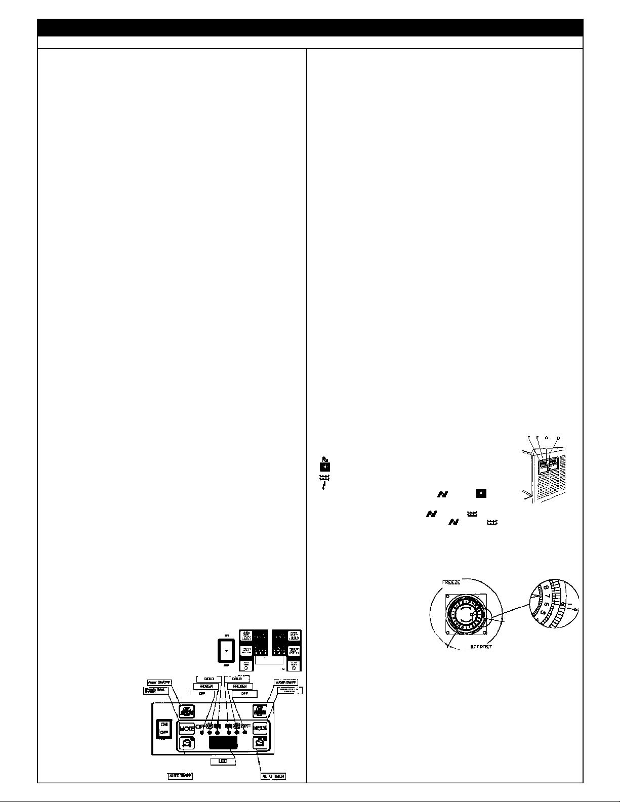
MG23-2B & ID2.2 TRADITIONAL ROCKER SWITCH MODEL
GUIDE
Important: The mixing parts/auger switch should be on prior
to activating the freezing or refrigeration switches.
(E) activates the mixing parts/spiral auger
(F) activates the freezing of the product
(G) activates the refrigeration of the product
(D) is the main power switch
FROZEN BEVERAGE - select (E) and (F)
Note: There is a 4 minute delay before the compressor starts.
COLD BEVERAGE - select (E) and (G)
STANDBY (Night Setting) - select (E) and (G)
* Defrost timers are installed in each unit and can be set to automatically
place units in defrost mode and back to frozen mode. All switches must be
on for defrost timer to properly function.
MG23-2B SETTING DEFROST TIMER (& ID2.2 When Equipped)
NOTE: All switches (power, auger, refrigeration and freeze) must be “on” for
defrost timer to properly function.
• Setting Current Time - Rotate
the program disc, in the
direction of the arrows,
to align the correct time of
day with the time of day mark
• Setting Defrost Mode Push the switch activator toward
the outer edge of the
program disc. Freeze time
is set by pushing the switch actuators toward the center of the time switch.
The light and dark shaded areas of the program disc indicate day and
night. Each actuator is equivalent to 15 minutes
• The drawing shows a defrost time from 11:00 to 6:15
THE TIMER IS BATTERY BACKED TO PROTECT SETTINGS DURING
POWER FAILURE. THE BATTERY BACK-UP FEATURE WILL FAIL IF
POWER IS REMOVED FROM THE UNIT FOR MORE THAN 2 WEEKS
Page 3

The following Preventative Maintenance Items should be performed per the recommended schedule in order to maximize the life of your machine and to insure
2. Check bell shaped shaft seal for wear and replace when needed (every 1-6 months or more often if necessary). Seal is worn if edges that touch barrel
Reassemble the rear back-lit merchandiser making sure that its slots are
d
c
a b
i
Key Replacement Parts
a) Drip Tray - Black 90409
Drip Tray - White 90026
b) Drip Tray Grid - Black 90408
Drip Tray Grid - White 90025
c) Incandescent Light Bulb 90142
d) Knob to secure Bowl - Black 90426
Knob to secure Bowl - White 90024
e) Upper Mixing Bar 90065
f) Seal for Bowl 90023
g) Dispensing Valve Handle - Black 90401
Dispensing Valve Handle - White 90041
h) Handle Securing Pin - Black 90402
Handle Securing Pin - White 90042
g h
e
f
m n
j
k
l
p q
o
ITEM DESCRIPTION PART NUMBERITEM DESCRIPTION PART NUMBER
i) Auger 90444
j) Spindle Bushing 90069
k) Shaft Seal, Rubber Bell Shaped - Black 90066
l) Securing Nut for Auger 90068
m)Dispensing Valve Spring 90044
n) Dispensing Valve Upper Body 90043
o) Food Grade Lubricant 90112
p) Dispensing Valve Lower Body - 90403
G & GM Series
Dispensing Valve Lower Body - 90045
ID Series
q) Dispensing Valve O-ring 90046
IMPORTANT-PREVENTATIVE MAINTENANCE
warranty coverage. (For a checklist of all P.M. items, contact GCS or check the website.)
1. Lubricate bell shaped shaft seal and dispense valve o-rings following daily cleaning procedure.
curl back.
3. Clean air filter weekly and condenser monthly or more often if necessary.
4. Check dispense valve o-rings for wear and replace as needed (every 3-6 months during complete PM or more often if necessary).
5. Perform complete PM every 3-6 months.
WARNING Disconnect the unit from its power supply prior to performing
!
any maintenance procedures. Failure to do so could result in electric
shock from hazardous parts or serious burns from hot surfaces.
REMOVING AND CLEANING THE FILTER IF EQUIPPED
(G & MG MODELS STANDARD; ID MODELS OPTIONAL)
In order to guarantee an efficient refrigerating system, it is
essential that the filter be properly cleaned, according to the
following procedures:
Attention: Failure to maintain a clean filter and condenser
!
will cause damage to the unit not covered by warranty.
• Unscrew the knob (K) on rear panel in order to have the
full back panel in your hands - (G, MG) on ID pull filter
cover from unit at bottom of cover, pull down to remove.
• Remove the filter (W) held inside the back panel (X) and
clean it properly using water or vacuum. Allow to dry.
• Put the clean dry filter back to its position and reinstall the back panel on
machine by screwing in the knob (K) or reattaching filter cover.
CLEANING CONDENSER
• Remove the back panel
• Using a dry brush or vacuum, remove the dust
that has accumulated between the fins of the
condenser
CHANGING LIGHT BULB
• To access the lightbulb insert the tip of a coin or
small screwdriver in the slot on the cover and
rotate to pop the panel open
• Holding the cover, carefully remove the lightbulb.
• Insert the new bulb and replace the light cover
REAR MERCHANDISER LIGHTS
• In order to access the lightbulb from the rear back
lit merchandiser, remove the rear merchandiser by
sliding it upwards.
• Then remove the lightbulb(s). Insert the new bulb(s).
•
inserted properly in the relevant brackets.
Page 4

INSTALLATION CONSISTENCY ADJUSTMENTS
Part # 90386
POSITIONING THE MACHINE
The machine must be well ventilated, with an 8” (20 cm) clearance on the sides and back of the machine. Do not install
near a heat source such as ovens, coffee machines, cold or
frozen beverage dispensers or ice machines (equipment with
compressors that expel hot air through its vents). Do not position near dust producing units such as a Powdered
Cappuccino or Cocoa dispenser. A room temperature
between 59ÞF (15ÞC) and 77ÞF (25ÞC) is recommended
REMOVE SHIPPING PIN
Attention: Shipping pin attached to tag located behind each bow must
!
be removed before starting machines.
CONSISTENCY ADJUSTMENTS
• Unplug the machine
• Product in bowl should be within proper fill range
• Change the thickness of product
by turning the screw (M) on the
back of bowl clockwise for thinner
product or counterclockwise for
thicker product
• The indicator gauge (N), located on the
8"
(20 cm)
back of the bowl, shows the degree of
adjustment (+/-) (+) = thicker, (-) = thinner
TOO THICK OF A PRODUCT CAN BE PREVENTED BY SWITCHING THE
FREEZING MODE (F) "OFF" OR BY REFILLING THE BOWL WHEN
PRODUCT IS BELOW MINIMUM FILL LINE
PRODUCT HINTS
• To maintain product quality place unit in standby (refrigeration) mode at
night to allow product to thaw out, and then refreeze the next day. This
will promote smoother product and smaller ice crystal growth. (Defrost
INSTALLING THE TOP LID MERCHANDISER
(requires Phillips head screwdriver)
1. Remove hole plugs and screws.
2. Remove or replace graphic by sliding
it around the outside edge of the lid’s
clear plastic base. Position bottom edge of
header in grooved area.Reassemble the
top cover onto the clear plastic base. The
top edge of header should slide into top
cover grooved area.
INSTALLING REAR GRAPHIC
1. Pinch or bend graphic and pull it out to
remove.
CONNECTION TOMAIN POWER SUPPLY
Install in properly grounded, electrical receptacle that is in compliance with current
national safety standards. Grindmaster Crathco Systems, Inc. is not responsible for
damage and/or injury caused by failure to follow above precautions.
• Only connect to a dedicated outlet.
timer can be programmed to do this for you automatically at preset
times.)
HELPFUL HINTS
PREPARING PRODUCT
• Make sure that your product has a 13% minimum
sugar content (BRIX). A lower concentrate could
damage the mixing parts and gear motors.
NEVER USE ONLY WATER.
• Premix all product in a separate container.
NEVER pour dry powder, crystals or concentrate
into a dry bowl.
• There is no need to remove lid for refilling.
Simply slide lid back until “stops” are reached.
• Note and follow minimum and maximum fill
lines on bowl. Do not overfill, or run the unit
without enough product.
• Altering the cord or plug will void the warranty.
• Do not compress, bend or bunch power cord or use extension cord.
TROUBLESHOOTING GUIDE
Problem Possible Cause Solution
The machine over-freezes, making the auger
movement slow or stopped
Product is leaking out of the bowl
The machine does not cool, or cools only
partially, but the compressors are running
The cover does not fit properly on the bowl
Product is leaking from the dispensing valve
Product is flowing into drain tray through
drainage tube
The auger and/or the upper mixing unit is
not turning
• The product brix is too low
• The screw setting for the product consistency control system is
set too far toward the “+” position
• The level of the product in the bowl is too low, exposing the
auger
• One of the bowl seals is not in place
• Freezer is in defrost mode
• The space around the machine is inadequate for ventilation
• The condenser fins are clogged with airborne particles
• The bowl is incorrectly positioned.The lower right and/or left
corner edge of bowl is not over the lower triangle edge
• The dispening valve has been incompletely or incorrectly
replaced in its position
• The free movement of the dispensing valve is impeded
• Dispensing valve o-rings are damaged
• The bell shaped “shaft” seal between the front of the cylinder
and the auger hub has not been reinstalled properly
• Auger not turned on
• Check the product brix and correct
• Reset the screw toward the “-” position to
produce a thinner consistency product
• Add more product or turn the refrigeration “Off”
• Replace or reposition the seals
• Return to freeze mode
• Allow at least 8" between the machine and
anything next to it; keep away from heat sources
• Remove the side panels and using a brush or
compressed air to clean the condenser
• Remove bowl and position properly
• Reassemble and replace
• Clean and lubricate the valve and valve cylinder with
the lubricant provided with the machine
• Replace the o-rings
• Find the seal and put it back in place
• Turn auger on
Grindmaster Crathco Systems, Inc. 1999
PRINTED IN USA
If you still need help, call our service department at (800) 695-4500 (Monday through Friday, 8 am - 6 pm EST) or an authorized service center in your
area. Please have the model and serial numbers ready so that accurate information may be given.
Prior authorization must be obtained from Grindmaster Crathco Systems’ Technical Services Department for all warranty claims.
0101 Form # CC-904-04
 Loading...