


User’s Guide
for the
CRATE AUDIO |
PM62S, PM82S |
& PM82T |
Powered Mixers
with
Digital Signal Processing
In order to achieve maximum performance from your new Crate Audio Mixer we recommend that you read this user’s guide prior to its use.
PM62S/PM82S/PM82T Powered Mixers
Congratulations.
You are now the proud owner of the compact and versatile Crate Audio PM62S/PM82S/PM82T powered mixer with Digital Signal Processing. In order to obtain the best performance from your new mixer, please read this User’s Guide prior to its use.
And Thank You, from 


Table of Contents:
Features . . . . . . . . . . . . . . . . . . . . . . . . . . . . . . . . . . . . . . . .3
The Mono Input Channels . . . . . . . . . . . . . . . . . . . . . . . . . .4
The Stereo Input Channels . . . . . . . . . . . . . . . . . . . . . . . . . .5
The Master Section . . . . . . . . . . . . . . . . . . . . . . . . . . . . . .6,7
The Rear Panel . . . . . . . . . . . . . . . . . . . . . . . . . . . . . . . . . .8
The DSP Section . . . . . . . . . . . . . . . . . . . . . . . . . . . . . . . . .9
System Block Diagram . . . . . . . . . . . . . . . . . . . . . . . . . .10,11
Technical Specifications . . . . . . . . . . . . . . . . . . . . .back cover
CAUTION
RISK OF ELECTRIC SHOCK
DO NOT OPEN
WARNING: TO REDUCE THE RISK OF FIRE OR ELECTRIC SHOCK, DO NOT EXPOSE THIS APPARATUS TO RAIN OR MOISTURE. TO REDUCE THE RISK OF ELECTRIC SHOCK, DO NOT REMOVE COVER. NO USER-SERVICEABLE PARTS INSIDE. REFER SERVICING TO QUALIFIED SERVICE PERSONNEL.
PRECAUCION
RIESGO DE CORRIENTAZO
NO ABRA
PRECAUCION: PARA REDUCIR EL RIESGO DE INCENDIOS O DESCARGAS ELECTRICAS, NO PERMITA QUE ESTE APARATO QUEDE EXPUESTO A LA LLUVIA O LA HUMEDAD. PARA DISMINUOIR EL RIESGO DE CORRIENTAZO. NO ABRA LA CUBIERTA. NO HAY PIEZAS ADENTRO QUE EL USARIO PUEDO REPARAR DEJE TODO MANTENIMIENTO A LOS TECHNICOS CALIFICADOS.
ATTENTION
RISQUE D'ELECTROCUTION
NE PAS OUVRIR
ATTENTION: PROTÉGEZ CET APPAREIL DE LA PLUIE ET DE L'HUMIDITÉ AFIN D'ÉVITER TOUT RISQUE D'INCENDIE OU D'ÉLECTROCUTION. POUR REDUIRE D'ELECTROCUTION NE PAS ENLEVER LE COUVERCLE. AUCUNE PIECE INTERNE N'EST REPRABLE PAR L'UTILISATEUR. POUR TOUTE REPARATION, S'ADRESSER A UN TECHNICIEN QUALIFIE.
IMPORTANT SAFETY INSTRUCTIONS
•READ, FOLLOW, HEED, AND KEEP ALL INSTRUCTIONS AND WARNINGS.
•DO NOT OPERATE NEAR ANY HEAT SOURCE AND DO NOT BLOCK ANY VENTILATION OPENINGS ON THIS APPARATUS. FOR PROPER OPERATION, THIS UNIT REQUIRES 3” (75CM) OF WELL VENTILATED SPACE AROUND HEATSINKS AND OTHER AIR FLOW PROVISIONS IN THE CABINET.
•DO NOT USE THIS APPARATUS NEAR SPLASHING, FALLING, SPRAYING, OR STANDING LIQUIDS.
•CLEAN ONLY WITH LINT-FREE DAMP CLOTH AND DO NOT USE CLEANING AGENTS.
•ONLY CONNECT POWER CORD TO A POLARIZED, SAFETY GROUNDED OUTLET WIRED TO CURRENT ELECTRICAL CODES AND COMPATIBLE WITH VOLTAGE, POWER, AND FREQUENCY REQUIREMENTS STATED ON THE REAR PANEL OF THE APPARATUS.
•PROTECT THE POWER CORD FROM DAMAGE DUE TO BEING WALKED ON, PINCHED, OR STRAINED.
•UNPLUG THE APPARATUS DURING LIGHTNING STORMS OR WHEN UNUSED FOR LONG PERIODS OF TIME.
•ONLY USE ATTACHMENTS, ACCESSORIES, STANDS, OR BRACKETS SPECIFIED BY THE MANUFACTURER FOR SAFE OPERATION AND TO AVOID INJURY.
•WARNING: TO REDUCE THE RISK OF ELECTRIC SHOCK OR FIRE, DO NOT EXPOSE THIS UNIT TO RAIN OR MOISTURE.
•SERVICE MUST BE PERFORMED BY QUALIFIED PERSONNEL.
•OUR AMPLIFIERS ARE CAPABLE OF PRODUCING HIGH SOUND PRESSURE LEVELS. CONTINUED EXPOSURE TO HIGH SOUND PRESSURE LEVELS CAN CAUSE PERMANENT HEARING IMPAIRMENT OR LOSS. USER CAUTION IS ADVISED AND EAR PROTECTION IS RECOMMENDED IF UNIT IS OPERATED AT HIGH VOLUME.
EXPLANATION OF GRAPHICAL SYMBOLS: |
"DANGEROUS VOLTAGE" |
EXPLICACION DE SIMBOLOS GRAFICOS: |
= “VOLTAJE PELIGROSO” |
EXPLICATION DES SYMBÔLES GRAPHIQUES: |
"DANGER HAUTE TENSION" |
"IT IS NECESSARY FOR THE USER TO REFER TO THE INSTRUCTION MANUAL"
=“ES NECESARIO QUE EL USUARIO SE REFIERA AL MANUAL DE INSTRUCCIONES.” "REFERREZ-VOUS AU MANUAL D'UTILISATION"
2

PM62S/PM82S/PM82T Powered Mixers
Features:
The Input Channels:
•Peak LEDs for optimum level settings
•Three bands of equalization
•Monitor, effects, and pan controls
•Output level controls
•Pad switch (mono channels) to accommodate “hot” signals
•XLR balanced low impedance mic input jacks
•1/4” balanced high-Z line input jacks
The Master Section:
•Tri-Power! Three internal power amplifiers (PM82T only) - one for the monitor, two for the main speaker outputs
•Two internal power amplifiers (PM62S, PM82S) for the main speaker outputs
•Built in Limiter to prevent overdriving the amplifiers
•Two 7-band graphic EQs - one for monitor, one for mains
•Five-step LED displays with Limiter indicators for monitoring the output signals
•Effects send and return controls
•Switchable phantom power (+48V)
•16-Program Digital Signal Processor (DSP) with on/off switch
•Footswitch jack for remote control of DSP on/off
•Headphones jack with level control
•DSP line out/aux in jacks for external effects
•Tape in and tape out jacks for recording and play back
•Main and monitor line out jacks
This equipment has been tested and found to comply with the limits for a Class B digital device, pursuant to part 15 of the FCC Rules. These limits are designed to provide reasonable protection against harmful interference in a residential installation. This equipment generates, uses and can radiate radio frequency energy and, if not installed and used in accordance with the instructions, may cause harmful interference to radio communications. However, there is no guarantee that interference will not occur in a particular installation. If this equipment does cause harmful interference to radio or television reception, which can be determined by turning the equipment off and on, the user is encouraged to try to correct the interference by one or more of the following measures:
•Reorient or relocate the receiving antenna.
•Increase the separation between the equipment and the receiver.
•Connect the equipment into an outlet on a circuit different from that to which the receiver is connected.
•Consult the dealer or an experienced radio/TV technician for help.
Changes or modifications to this device not expressly approved by SLM Electronics could void the user’s authority to operate the equipment under FCC rules.
3
PM62S/PM82S/PM82T Powered Mixers
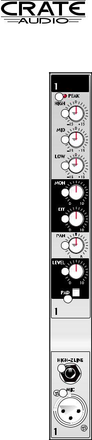
The Mono Input Channels:
1 |
2 |
3 |
4 |
5 |
6 |
7 |
8 |
9 |
10 |
11 |
1.PEAK LED: This LED illuminates when the input signal nears clipping. During normal operation, this LED will flash on strong signal peaks. If the LED remains illuminated, depress the Pad switch (#9) and/or reduce the level of the signal connected to the input jack (#10,11).
2.HIGH: Use this control to adjust the high frequency level for the channel.
3.MID: Use this control to adjust the midrange frequency level for the channel.
4.LOW: Use this control to adjust the low frequency level for the channel.
5.MON: Use this control to adjust the amount of the channel’s signal sent to the monitors.
6.EFFECT: Use this control to adjust the amplitude of the internal DSP effect (or external effects, if used) to be applied to the channel’s signal.
7.PAN: Use this control to adjust the left-to-right balance of the channel’s signal.
8.LEVEL: Use this control to adjust the channel’s output signal level.
9.PAD: Use this switch to accommodate “hot” input signals. (Signals too strong to allow a useful setting of the gain control without causing the Peak LED - #1- to remain illuminated.) Depress this switch to engage the 20dB pad, thereby reducing the input signal’s level to a more useable range.
10.HIGH-Z LINE: Use this jack to connect the output signal from a high impedance microphone or a line level signal (such as an instrument, rhythm machine, tape deck, etc.) to the mixer by means of a shielded cable terminated with a male 1/4” plug. Tip = “+,” ring = “–,” sleeve = shield.
11.MIC: Use this jack to connect the output signal from a low impedance microphone to the mixer by means of a shielded cable terminated with a male XLR plug. Pin 2 = “+,” pin 3 = “–,” pin 1 = shield.
4
 Loading...