

Page 1

Owner ’s Manual
Page 2
Congratulations!
Y ou are now the proud owner of the Crate GFX-65Tamplifier. This rugged amplifier combines
outstanding features with serious clean and distorted sounds. An easy to operate DSPsection lets
you dial in a variety of digital effects including reverbs, delays, octave and wah-wahs – with a separate level control. Crate’s unique Channel T racking feature means that as you switch between
channels and gains, the DSP automatically “tracks” the changes - your DSP settings for each
channel are stored and automatically recalled! The supplied three-button footswitch allows you to
select channels, change the overdrive gain, and turn the DSPon and off by “remote control.” The
top-mounted electronic tuner lets you get tuned and stay in tune any time the amplifier is on.
Like all Crate products, your GFX-65T is designed by musicians, and built using only the
best components. Extensive testing confirms that this amplifier is the absolute best it can be.
In order to get the most out of your new amplifier, we strongly urge you to read the information contained in this manual before you begin playing.
And thank you
for choosing
TABLE OF CONTENTS:
The Digital Signal Processor . . . . . . . . . . . . . . . . . . . . .3
Channel Tracking . . . . . . . . . . . . . . . . . . . . . . . . . . . . . .3
The Front Panel . . . . . . . . . . . . . . . . . . . . . . . . . . . . .4, 5
Suggested Settings . . . . . . . . . . . . . . . . . . . . . . . . . . . .6
System Block Diagram . . . . . . . . . . . . . . . . . . . . . . . . .7
Technical Specifications . . . . . . . . . . . . . . . . .back cover
GFX-65T Guitar Amplifier with DSP & Channel Tracking
IMPORTANT SAFETY INSTRUCTIONS
• READ, FOLLOW, HEED, AND KEEPALL INSTRUCTIONS AND WARNINGS.
• DO NOT OPERATE NEAR ANY HEATSOURCE AND DO NOT BLOCK ANY VENTILATION OPENINGS ON THIS APPARATUS.
• DO NOT USE THIS APPARATUS NEAR SPLASHING, FALLING, SPRAYING, OR STANDING LIQUIDS.
• CLEAN ONLY WITH LINT-FREE DAMP CLOTH AND DO NOT USE CLEANING AGENTS.
• ONLY CONNECT POWER CORD TO A POLARIZED, SAFETY GROUNDED OUTLET WIRED TO CURRENT ELECTRICAL CODES AND
COMPATIBLE WITH VOLTAGE, POWER, AND FREQUENCY REQUIREMENTS STATED ON THE REAR PANEL OF THE APPARATUS.
• PROTECT THE POWER CORD FROM DAMAGE DUE TO BEING WALKED ON, PINCHED, OR STRAINED.
• UNPLUG THE APPARATUS DURING LIGHTNING STORMS OR WHEN UNUSED FOR LONG PERIODS OF TIME.
• ONLY USE ATTACHMENTS, ACCESSORIES, STANDS, OR BRACKETS SPECIFIED BYTHE MANUFACTURER FOR SAFE OPERA-
TION AND TO AVOID INJURY.
• THIS APPARATUS DOES NOT OPERATE NORMALLY AND REQUIRES SERVICE WITH ANY PHYSICAL DAMAGE FROM IMPACT OR
ANY EXPOSURE TO MOISTURE.
• SERVICE MUST BE PERFORMED BY QUALIFIED PERSONNEL.
• OUR AMPLIFIERS ARE CAPABLE OF PRODUCING HIGH SOUND PRESSURE LEVELS. CONTINUED EXPOSURE TO HIGH SOUND
PRESSURE LEVELS CAN CAUSE PERMANENT HEARING IMPAIRMENT OR LOSS. USER CAUTION IS ADVISED AND EAR PROTECTION IS RECOMMENDED IF UNIT IS OPERATED AT HIGH VOLUME.
CAUTION
RISK OF ELECTRIC SHOCK
DO NOT OPEN
WARNING: TO REDUCE THE RISK OF FIRE OR ELECTRIC
SHOCK, DO NOT EXPOSE THIS APPARATUS TO RAIN OR MOISTURE. TO REDUCE THE RISK OF ELECTRIC SHOCK, DO NOT
REMOVE COVER. NO USER-SERVICEABLE PARTS INSIDE.
REFER SERVICING TO QUALIFIED SERVICE PERSONNEL.
"IT IS NECESSARY FOR THE USER TO REFER TO THE INSTRUCTION MANUAL"
“ES NECESARIO QUE EL USUARIO SE REFIERA AL MANUAL DE INSTRUCCIONES.”
"REFERREZ-VOUS AU MANUAL D'UTILISATION"
EXPLANATION OF GRAPHICAL SYMBOLS:
EXPLICACION DE SIMBOLOS GRAFICOS:
EXPLICATION DESSYMBÔLES GRAPHIQUES:
"DANGEROUS VOLTAGE"
“VOLTAJE PELIGROSO”
"DANGER HAUTE TENSION"
=
=
PRECAUCION
RIESGO DE CORRIENTAZO
NO ABRA
ADVERTENCIA: REDUCIR EL RIESGO DE FUEGO O CHOQUE ELÉCTRICO, NO LE EXPONE DE ESTE APARATO A LLUVIA O HUMEDAD. PARA
DISMINUOIR EL RIESGO DE CORRIENTAZO. NO ABRA LA CUBIERTA.
NO HAY PIEZAS ADENTRO QUE EL USARIO PUEDO REPARAR DEJE
TODO MANTENIMIENTO A LOS TECHNICOS CALIFICADOS.
ATTENTION
RISQUE D'ELECTROCUTION
NE PAS OUVRIR
ATTENTION: POUR REDUIRE D'ELECTROCUTION NE PAS
ENLEVER LE COUVERCLE. AUCUNE PIECE INTERNE N'EST
REPRABLE PAR L'UTILISATEUR. POUR TOUTE REPARATION,
S'ADRESSER A UN TECHNICIEN QUALIFIE.
Page 3
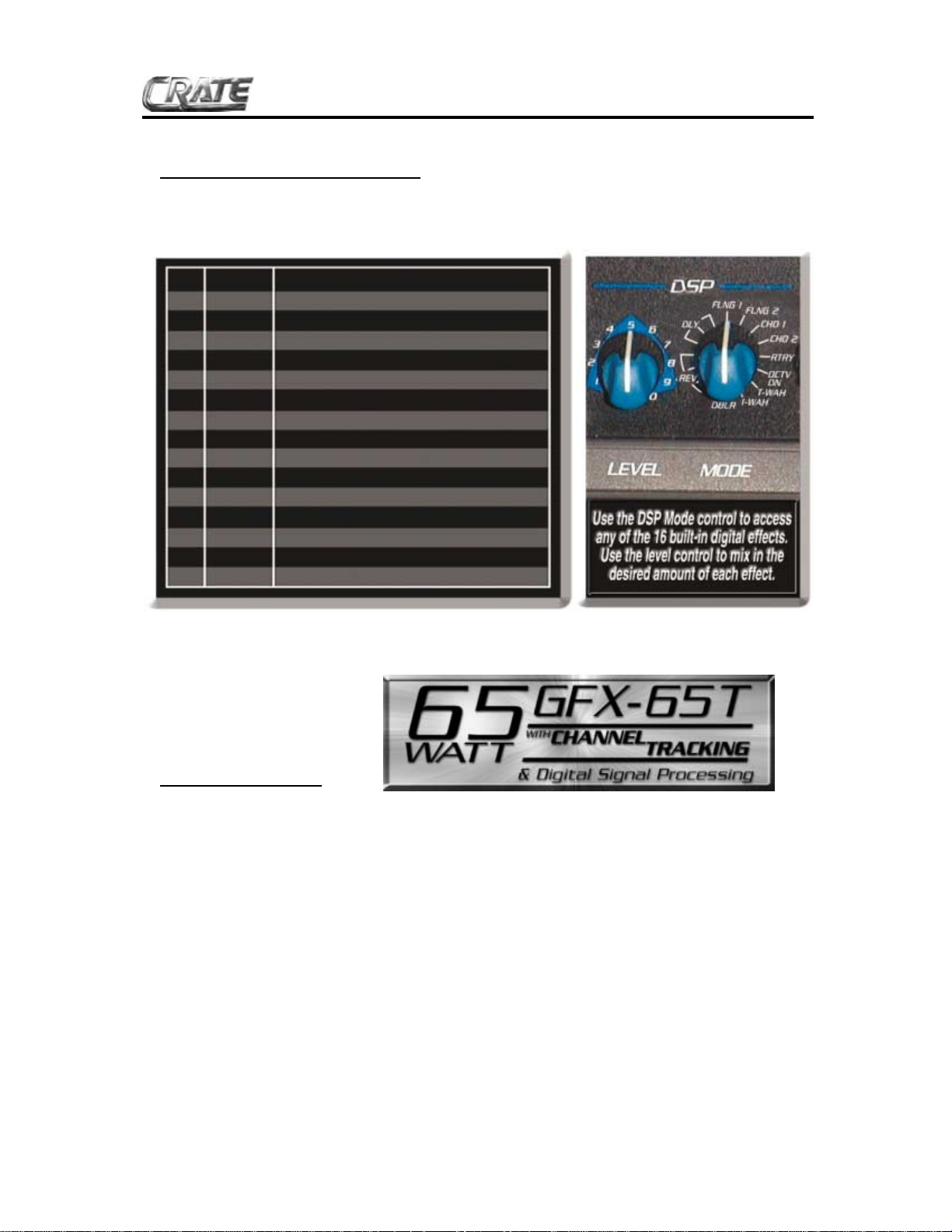
The Digital Signal Processor:
Crate’s Digital Signal Processing offers 16 exciting digital effects, accessible through the DSP
Mode control. The effects are described below .
3
GFX-65T Guitar Amplifier with DSP & Channel Tracking
Channel T
racking:
Your Crate GFX-65T gives you the power of Channel Tracking! Once you select a DSP setting
for each channel, Channel Tracking recalls those DSP settings automatically – without changing
the DSP controls! For example:
• Select the Clean channel. Set the DSP Mode to “FLNG 1”
(slow flange + reverb)
• Select the Overdrive channel, Gain 1. Set the DSP Mode to “CHO 1”(slow chorus + reverb) (the set-
ting for the Clean channel is now saved to memory)
• Select the Overdrive channel, Gain 2. Set the DSP Mode to “T-WAH” (touch wah-wah) (the setting
for the Overdrive channel, Gain 1 is now saved to memory)
• Reselect the Clean channel (the setting for the Overdrive channel, Gain 2 is now saved to memory)
Now when you go back to the Clean channel, even though the DSP Mode was last set to “T-WAH,”
Channel Tracking automatically recalls the last setting for the Clean channel – in this example,
“FLNG 1.” Change to the Overdrive channel, Gain 1, and “CHO 1” is recalled. Change to the
Overdrive channel, Gain 2, and “T-WAH” is recalled. That’s the power of Channel Tracking!
(Note: Even when the power is turned off, Channel T racking still retains the settings – until you change them!)
1 REV 1 small room reverb
2 REV 2 medium room reverb
3 REV 3 large room reverb
4 REV 4 concert hall reverb
5 DLY 1 short slapback + small room reverb
6 DLY 2 medium delay + plate reverb
7 DLY 3 long delay + large room reverb
8 FLNG 1 slow deep flange + reverb
9 FLNG 2 flange + reverb + delay
10 CHO 1 slow tremolo chorus + reverb
11 CHO 2 chorus + reverb + delay
12 RTRY simulated rotating speaker effect
13 OCTV DN adds a signal one octave lower than input
14 T-WAH touch sensitive wah-wah effect
15 I-WAH inverse wah-wah effect
16 DBLR simulated second track, slightly out-of-sync
Page 4

The Front Panel:
4
1 2 3 4 6 7 8 10 11 12 13 14 15 16 17 19185 9
1: INPUT : Use this 1/4” jack to connect your guitar to the amplifier by means of a shielded instrument cable.
OVERDRIVE CHANNEL: A high gain channel giving you sounds from a slight edge to serious overdrive.
2: GAIN 1: Use this control to adjust the amount of light distortion for the Overdrive channel. Gain 1 produces less intense distortion than Gain 2 (#3) and is active when the Gain switch (#5) is in the out position.
3: GAIN 2: Use this control to adjust the amount of heavy distortion for the Overdrive channel. Gain 2 produces more intense distortion than Gain 1 (#2) and is active when the Gain switch (#5) is depressed.
4: SHAPE: Use this control to “dial in” the tone for the Overdrive channel when Gain 2 is selected. Rotating
the control counterclockwise enhances the mid frequencies, while rotating the control clockwise enhances
the low and high frequencies. This control is active only when Gain 2 is selected.
5: GAIN SELECT: Use this switch to select which gain control is active for the Overdrive channel. With the
switch in the out position, Gain 1 is selected. When the switch is depressed, Gain 2 is selected.
6: LOW: Use this control to adjust the low frequency level of the Overdrive channel.
7: HIGH: Use this control to adjust the high frequency level of the Overdrive channel.
8: LEVEL: Use this control to adjust the output level of the Overdrive channel.
9: CHANNEL SWITCH: Use this switch to select either channel. With the switch in the out position, the
Clean channel is selected. When the switch is depressed, the Overdrive channel is selected.
CLEAN CHANNEL: A normal gain channel designed to give you crystal clear sounds to medium distortion.
10: LEVEL: Use this control to adjust the output level of the Clean channel.
11: LOW: Use this control to adjust the low frequency level of the Clean channel.
12: MID: Use this control to adjust the midrange frequency level of the Clean channel.
13: HIGH: Use this control to adjust the high frequency level of the Clean channel.
14: DSP LEVEL: Use this control to adjust the amount of digital effect: in its fully counterclockwise posi-
tion the signal will be “dry” (without any effect). As you rotate the control clockwise the amount of effect
increases.
15: DSP MODE:Use this control to select one of the 16 built-in digital effects. Alisting of the effects is shown
on page 3 of this manual.
16: INSERT: Use this jack to connect an external effects device to the amplifier. Use a stereo 1/4” male Y
connector: ring = send, tip = return, sleeve = ground. (Refer to the illustration at the bottom of page 5.)
17: EXTERNAL SPEAKER: Use this jack to connect the amplifier to an external speaker. The internal
speaker is disconnected when this jack is used. The minimum impedance for the external speaker is 4 ohms.
18: ON LED: This LED will illuminate when power is applied to the amplifier.
19: POWER: Use this switch to turn the amplifier on (top of the switch depressed) and off (bottom of the
switch depressed).
GFX-65T Guitar Amplifier with DSP & Channel Tracking
Page 5

The Electronic Tuner:
5
20. ELECTRONIC TUNER (top panel): This active electronic tuner is on whenever the amplifier is turned
on, allowing you constant, “real-time” tuning. The bottom row of LEDs indicate which string is being tuned,
while the top row of LEDs are your guiding lights: use the flat and sharp indicators until the center LED illuminates. This indicates a properly tuned string.
21: AC LINE CORD (rear panel, not shown): This grounded power cord is to be plugged into a grounded power outlet, wired to current electrical codes and compatible with the voltage, power, and frequency
requirements stated on the rear panel. Do not attempt to defeat the safety ground connection.
21: FUSE (rear panel, not shown): The fuse protects the amplifier from damages caused by a faulty
AC power source and/or other problems. If the fuse opens, replace it ONL Ywith the same size and type.
If fuses continue to fail, check the AC source – if the source is okay, contact your Crate dealer for service information.
22: CHANNEL SELECT / GAIN FOOTSWITCH JACK (rear panel, not shown): Use this jack to connect the stereo 1/4” plug of the supplied three-button footswitch for remote control of channel selection
and gain selection.
23: REVERB FOOTSWITCH JACK (rear panel, not shown): Use this jack to connect the mono 1/4”
plug of the supplied three-button footswitch for remote control of DSP on and off.
CONNECTING T
O THE INSERT JACK:
The Insert jack (#16) allows
you to patch an external
effects device into the amplifier
prior to its power amp stage.
Use Crate’s STP201, STP202
or STP203 stereo-to-mono Y
cord or an adapter such as
Crate’s YPP117 and two 1/4”
mono signal cables to connect
the effect as shown to the
immediate right.
GFX-65T Guitar Amplifier with DSP & Channel Tracking
20
Stereo-to-mono Y-cord:
to Insert
(STP201, 3'
STP202, 6'
STP203, 9')
jack
TIP
RING
SLEEVE
RETURN
SEND
GROUND
Y-adapter and 2 cables:
TIP
to Insert
RING
SLEEVE
(YPP117)
jack
TIP
TIP
RING
RING
to
effect
"OUT"
jack
to
effect
"IN"
jack
(1/4"-TO-1/4"
MONO CABLES)
to
effect
"OUT"
jack
effect
to
"IN"
jack
External Effect
External Effect
Page 6

Suggested Settings:
6
GFX-65T Guitar Amplifier with DSP & Channel Tracking
Page 7

System Block Diagram:
7
R
GFX-65T Guitar Amplifier with DSP & Channel Tracking
TUNER
A BC D EF G
INPUT
BUFFER
FLEX WAVE
OVERDRIVE
CHANNEL
GAIN
STAGE
SHAPE
ACTIVE
GAIN
CLEAN
CHANNEL
LOWLEVEL MID HIGH
EQ
LOW
HIGH LEVEL
CHANNEL
SELECT
DSP
MODE
SHAPE
LEVEL
MIX
AMP
POWER
AMP
DAMPING
CIRCUIT
INSERT
SPEAKE
EXT.
SPEAKER
Page 8

GFX-65T TECHNICAL SPECIFICATIONS:
Output Power Rating 65W RMS @ 5% THD, 4Ω, 120 VAC
Speaker Size and Rating (1) Custom Design 12”, 4Ω
Input Impedance 470kΩ
Total System Gain Overdrive Ch Gain 1: 88dB, all controls @10; Gain 2: 110dB
Clean Ch 58dB, all controls @10
Maximum Input Signal Accepted 7 volts peak-to-peak
Overdrive Channel Low Control 11dB range @ 80Hz
Shape Control Proprietary Circuit
High Control 10dB range @10kHz
Clean Channel Low Control 22dB range @ 80Hz
Mid Control 14dB range @ 600Hz
High Control 28dB range @ 10kHz
Power Requirements 120 VAC, 60Hz, 90VA; 100/115VAC, 50/60Hz, 90VA;
100/115VAC, 50/60Hz, 90VA
Size and Weight 17-1/2” H x 20” W x 11” D, 34 lbs.
The GFX-65T is covered with a durable charcoal gray Tolex material: wipe it clean with a lint-free cloth.
Never spray cleaning agents onto the cabinet. Avoid abrasive cleansers which would damage the finish.
Crate continually develops new products, as well as improves existing ones. For this reason, the specifications
and information in this manual are subject to change without notice.
www.crateamps.com
@2001 SLM Electronics, a division of St. Louis Music, Inc • 1400 Ferguson Avenue • St. Louis, MO 63301
47-475-05 • 09/01
GFX-65T Guitar Amplifier with DSP & Channel Tracking
Declaration Of Conformity
#34, Effective 01-01-2001
Manufacturer’s Name: SLM Electronics
Production Facility: 11880 Borman Drive, St. Louis, MO 63146, USA
Production Facility: 700 Hwy 202 W, Yellville, AR 72687, USA
Shipping Facility: 1400 Ferguson Ave., St. Louis, MO 63133, USA
Office Facility: 1400 Ferguson Ave., St. Louis, MO 63133, USA
Product Type: Audio Amplifier
Complies with Standards:
LVD: 92/31/EEC, 93/68/EEC, & 73/23/EWG
Safety: EN60065
EMC: EN55013, EN55020, EN55022, EN61000-3-2,
& EN61000-3-3
Supplementary information provided by your local Sales & Services Office or:
SLM Electronics - R & D Engineering
1901 Congressional Drive, St Louis, MO 63146, USA
Tel.: 314-569-0141, Fax: 314-569-0175
 Loading...