

Page 1
G40CXL STEREO
CHORUS AMPLIFIER
We would like to take this opportunity to thank you for selecting a Crate product, and to tell you
of our commitment to the design and manufacture of only the finest musical instrument amplification equipment; built for you, the musician.
You have purchased one of the most innovative sound amplification devices available today.
Your Crate amplifier gives you more performance features than ever before; features that you,
the musician, have asked for.
Your Crate amplifier is proudly Made in America. Only the finest available components and
materials are used in the manufacture of each amplifier.
All Crate amplifiers are subject to seven or more inspection and testing steps to assure you of
a high quality product. The final test for each amp is conducted by a trained musician with the
instrument the amp was designed for. Any unit that does not meet the standards of his discriminating ear will not be passed.
Since all Crate products are designed, developed and manufactured through the cooperative
efforts of engineers and professional musicians, the end result is a product that responds to the
musician’s audio requirements, and a product that will serve your needs for years to come.
OWNER’S MANUAL
Page 2
G40CXL Amplifier
010010
0dB -6dB INSERT HEADPHONES
INPUT CHANNEL A
GAIN
010
LEVEL
010
CHORUS
DEPTH
010
RATE
010 010 010
CHANNEL B REVERB
010
SHAPE VOLUME LOW MID
010
HIGH DEPTHON
BRIGHT
CHANNEL
SELECT
A B
ON POWER
1 2 3 4 5 6 7 8 9 10 11 12 13 14 15 16 17 18
19
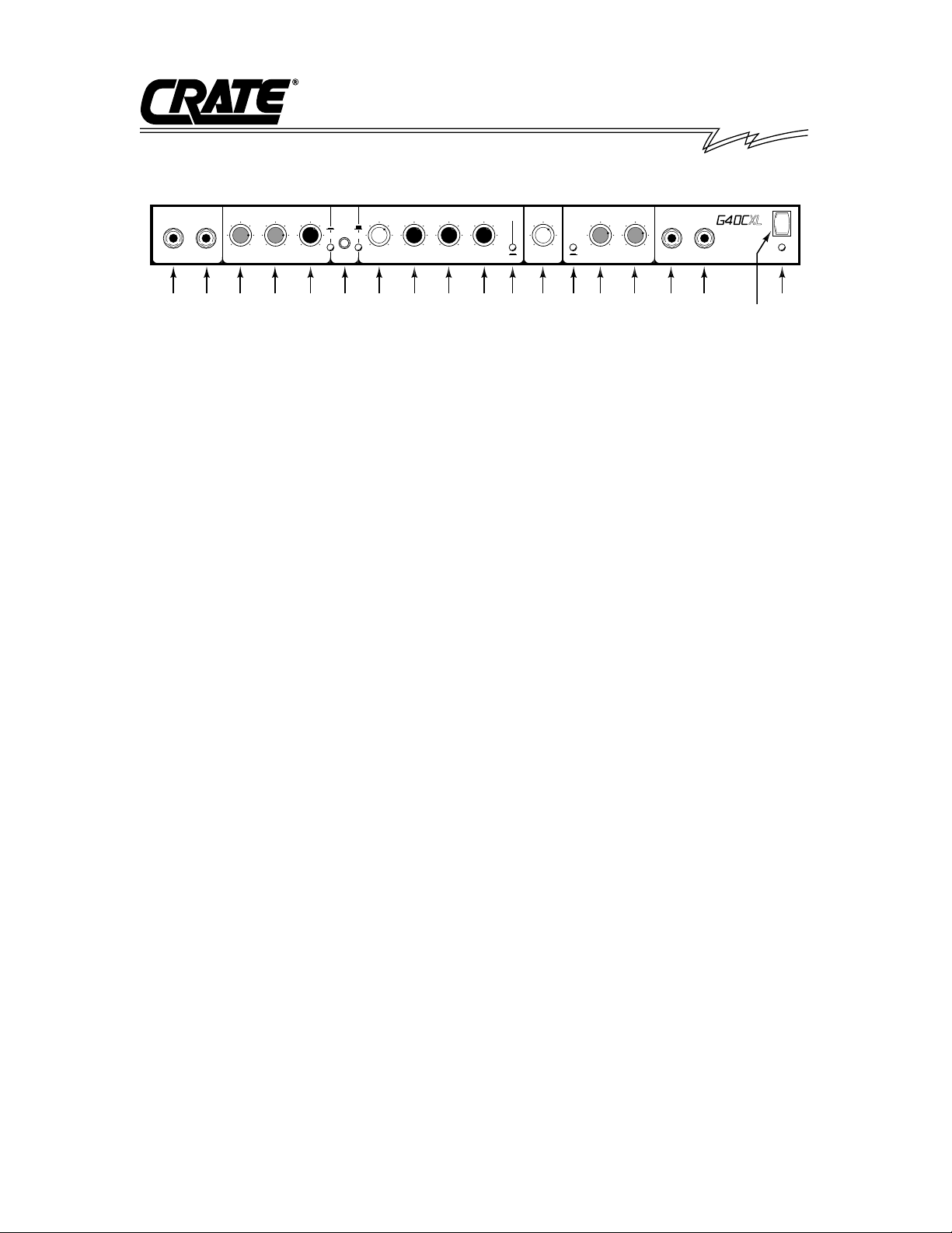
FRONT PANEL – INPUT
SECTION
1. 0dB INPUT JACK: This input accepts a
standard 1/4” phone plug and is suitable
for any low to line level signal source
such as an electric guitar.
2. -6dB INPUT JACK: This input jack also
accepts a standard 1/4” jack but is
padded 6 dB for hotter inputs such as
tape decks or guitars with hot pickups. If
both jacks are used, this input is not
padded and will be equal to the 0 dB
input jack.
CHANNEL A CONTROLS:
3. GAIN CONTROL: This control sets the
amount of gain for Channel A and is
used to vary the amount of distortion.
Minimal distortion is achieved with this
control rotated counter-clockwise. A
fully clockwise setting creates maximum
distortion.
4. LEVEL CONTROL: The overall volume
of Channel Ais controlled with this knob
and should be used in conjunction with
the Gain Control (3).
5. SHAPE CONTROL: This is the overall
tone control for Channel A. When
turned to the left, a setting with heavy
emphasis on mid range is achieved.
When rotated to the right, the amp creates a “fat” sound with extra boost on
lows and highs.
6. CHANNEL SELECT SWITCH: This
switch is used to select between
Channel Aand Channel B. When using
the optional footswitch (23), this switch
is inoperative.
CHANNEL A CONTROLS:
7. VOLUME CONTROL: This control sets
the overall listening level of Channel B.
This control is independent of any setting made in Channel A.
8. LOW CONTROL (Bass): The desired
amount of “Bottom” or “Warmth” may be
increased or decreased with this knob.
9. MID CONTROL (Mid): The tonal qualities of the midrange are very important
to a good guitar sound. This knob can
“thin-out” the sound when turned down,
or “fatten-up the sound when larger
amounts are used.
10. HIGH CONTROL (Treble): This knob
will affect the upper harmonic range of
the guitar. Boosting it sharpens or adds
crispness to the sound. For additional
effect, use this control in conjunction
with the Bright Switch (11).
11. BRIGHT SWITCH: This switch affects
the brilliance of the guitar’s sound by
adding additional “bite” or sharpness.
This switch affects both Channel A and
B.
12. DEPTH CONTROL (REVERB): This
control allows the player to alter the
apparent acoustical qualities of a room.
The sound can be altered from very
“Flat” or “Dry” when the control is turned
off, to that of a concert hall when used
in larger amounts.
CHORUS SECTION
13. CHORUS SWITCH: This switch turns
on the stereo chorus when depressed.
It must be in this position to enable the
chorus footswitch (24).
Page 3

G40CXL Amplifier
14. DEPTH: This control sets the amount or
depth of the chorus effect.
15. RATE: This control sets the sweep
speed of the chorus effect. Together,
these two chorus controls determine the
overall chorus effect from a slow , “phasing” sound to a lively, shimmering effect
and beyond. The stereo nature of the
G40CXL gives a “three-dimensional”
quality to the unit making it sound full
and “alive.”
16. INSERT JACK: This stereo 1/4” jack is
a line out (tip)/line in (ring) jack.
17. HEADPHONES JACK: Standard
stereo headphones may be plugged
into this jack. This disconnects all
speakers from the unit. allowing private
listening.
18. ON/OFF LED INDICA TOR: The amplifier is on when this LED is lit.
19. ON/OFF SWITCH: This is a two-position switch; the down position will turn
the unit on, while the up position will
turn the unit off.
RIGHT
MODEL #
120 VAC 60 Hz 200 WATTS MAX LEFT
EXT. SPEAKER
21 22
RIGHT
CAUTION:
TO REDUCE THE RISK OF ELECTRIC SHOCK, DO NOT REMOVE
CHASSIS. NO USER SERVICEABLE PAERTS INSIDE. REFER ALL SERVICING
TO QUALIFIED SERVICE PERSONNEL. TO REDUCE THE RISK OF FIRE OR
ELECTRIC SHOCK, DO NOT EXPOSE THIS APPLIANCE TO PAIN OR MOISTURE.
LEFT
LINE OUT
CH. SELECT/
REVERB
CHORUS
FOOTSWITCH
242320
G40CXL
SERIAL #
A
made in USA by
SLM Electronics
1400 Ferguson Ave.
St. Louis, Mo. 63133
20. POWER CORD: Your G40CXLis equipped
with a heavy-duty grounded three-wire
power cord. Be sure this cord is properly
plugged into a safely wired grounded 120
volt, 60 Hz AC power outlet before use. (If
your G40CXL was purchased outside the
United States, refer to the rear panel for
power ratings.) For your safety, never
attempt to defeat the ground connection
on this cord.
21. EXTERNAL SPEAKER JACKS:
These jacks are for additional speaker
hookup. Any number of speakers may
be added since these jacks are in
series with the internal speakers.
22. LINE OUT JACKS: These jacks are
used to connect the unit to additional
amplifiers or to connect the amp to a
tape recorder or mixing board. Using
both the left and right outputs will preserve the proper stereo signal. External
speakers cannot be connected to these
jacks.
23. CHANNEL/REVERB FOOTSWITCH
JACK: This jack is to be used with the
Channel Selector/Reverb footswitch.
24. CHORUS FOOTSWITCH JACK: This
jack is to be used with any standard
footswitch to control the chorus. The
Chorus Switch (13) must be depressed
to enable this footswitch.
REAR PANEL
Page 4
G40CXL TECHNICAL SPECIFICATIONS:
Output Power Rating 40 watts RMS @ 5% THD
4 ohm load – 120 VAC line
Speaker Size and Rating G40CXL: Custom Design 8”
Power Handling 20 watts RMS
G40CXLS: Celestion G8L-35
Bass Control 30dB range @ 100 Hz
Mid Control 12dB range @ 1 kHz
Treble Control 26dB range @ 5 kHz
Bright Switch 8dB boost @ 6 kHz
Input Impedance 220k ohms/”0dB” input
44k ohms/”-6dB” input
Maximum Input Signal Level Accepted 4 volts peak to peak/”0dB” input
8 volts peak to peak/”-6dB” input
Total System Gain Channel A: 88dB @ 1 kHz
(Shape @ 0, Bright Switch off)
Channel B: 58dB @ 1 kHz
(Controls @ 10, Bright Switch off
Signal To Noise Ratio Channel A: 51dB – with Gain @10 Shape @0 Level @10
Channel B: 62dB – with all controls @10, Bright Switch off
Input Power Requirements 120 VAC, 60Hz, 200 watts max
Fuse Rating and Type 2 amp Slo-Blo, 250V internal
Cabinet Size and Weight 15-1/2” H x 20-3/4” W x 8-3/4” D, 30 lbs.
CRATE/SLM ELECTRONICS, A DIVISION OF ST. LOUIS MUSIC, 1400 FERGUSON, ST. LOUIS, MO. 63133
P/N 47-569-05 • 12/95
G40CXL Amplifier
THIS EQUIPMENT HAS BEEN DESIGNED AND ENGINEERED TO PROVIDE SAFE AND RELIABLE OPERATION. IN ORDER TO PROLONG THE LIFE OF THE
UNIT AND PREVENTACCIDENTAL DAMAGES OR INJURY, PLEASE FOLLOW THESE PRECAUTIONARY GUIDELINES:
CAUTION: TO REDUCE THE RISK OF ELECTRIC SHOCK, DO NOT OPEN CHASSIS; DO NOT DEFEAT OR REMOVE THE GROUND PIN OF THE POWER
CORD; CONNECT ONLYTO A PROPERLYGROUNDED AC POWER OUTLET.
WARNING: TO REDUCE THE RISK OF FIRE OR ELECTRIC SHOCK, DO NOT EXPOSE THIS EQUIPMENT TO RAIN OR MOISTURE.
CAUTION: NO USER-SERVICEABLE PARTS INSIDE. REFER SERVICING TO QUALIFIED SERVICE PERSONNEL.
CAUTION: OUR AMPLIFIERS ARE CAPABLE OF PRODUCING HIGH SOUND PRESSURE LEVELS. CONTINUED EXPOSURE TO HIGH SOUND PRESSURE
LEVELS CAN CAUSE PERMANENT HEARING IMPAIRMENT OR LOSS. USER CAUTION IS ADVISED AND EAR PROTECTION IS RECOMMENDED IF UNIT IS
OPERATED AT HIGH VOLUME.
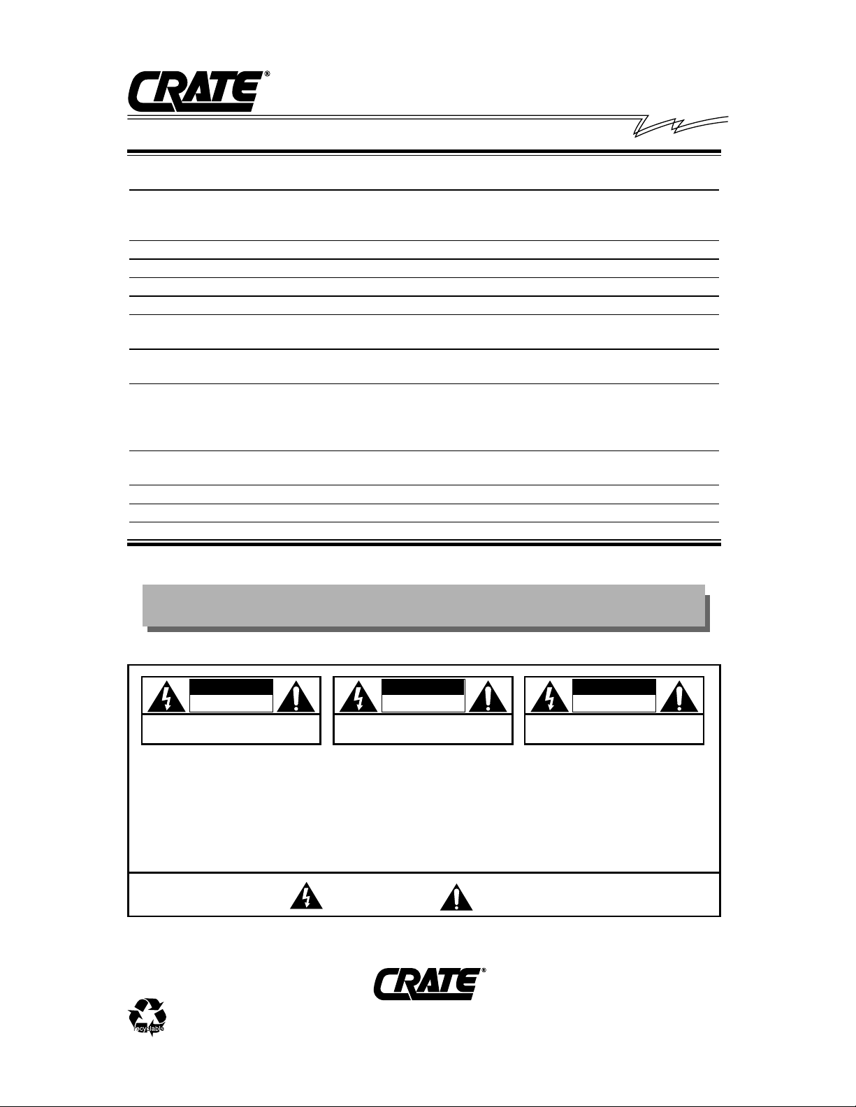
CAUTION
RISK OF ELECTRIC SHOCK
DO NOT OPEN
CAUTION: TO REDUCE THE RISK OF ELECTRIC SHOCK,
DO NOT REMOVE COVER.
NO USER-SERVICEABLE PARTS INSIDE.
REFER SERVICING TO QUALIFIED SERVICE PERSONNEL.
"IT IS NECESSARY FOR THE USER TO REFER TO THE INSTRUCTION MANUAL"
"REFERREZ-VOUS AU MANUAL D'UTILISATION"
"UNBEDINGT IN DER BEDIENUNGSANLEITUNG NACHSCHLAGEN"
EXPLANATION OF GRAPHICAL SYMBOLS:
"DANGEROUS VOLTAGE"
"DANGER HAUTE TENSION"
"GEFAHLICHE SPANNUNG"
=
=
ATTENTION
RISQUE D'ELECTROCUTION
NE PAS OUVRIR
ATTENTION: POUR REDUIRE D'ELECTROCUTION NE PAS
ENLEVER LE COUVERCLE. AUCUNE PIECE INTERNE N'EST REPRABLE
PAR L'UTILISATEUR. POUR TOUTE REPARATION, S'ADRESSER A UN
TECHNICIEN QUALIFIE.
VORSICHT
ELEKTRISCHE SCHLAGGEFAHR
NICHT OFFENEN
VORSICHT: ZUR MINIMIERUNG ELEKTRISCHER SCHLAGGEFAHR NICHT
DEN DECKEL ABENHMEN. INTERNE TEILE KONNEN NICHT VOM
BENUTZER GEWARTET WERDEN. DIE WARTUNG IS QUALIFIZIERTEM
WARTUNGSPERSONAL ZU UBERLASSEN.
Crate continually develops new products, as well as improves existing ones. For this reason, the
specifications and information in this Crate manual are subject to change without notice.
 Loading...