

Page 1
BV150H Three Channel Guitar Amplifier
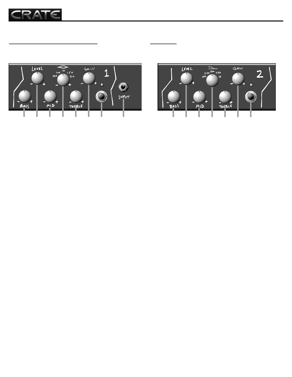
The Front Panel – Input, Channel 1:
1. INPUT JACK: Use this 1/4” jack to connect your guitar to the
amplifier by means of a shielded instrument cable.
2. CH. 1 SELECT SWITCH: This switch, when activated, selects
Channel 1. The green LED above the switch illuminates when
Channel 1 is selected. When the footswitch (#28, rear panel) is connected, either the front panel select switches or the footswitch may
be used to select the active channel.
3. GAIN: Use this control to adjust the input gain for Channel 1. With
the control rotated counter clockwise, the resulting tones are tight
and dynamic. As you rotate the control clockwise the tones take on
more crunch.
4. TREBLE: Use this control to adjust the high frequency output of
Channel 1. The Channel 1 Treble control provides an adjustment
range of 38dB at 5kHz.
5. MID FREQ SELECT: Use this rotary switch to select the frequency
for the Mid control (#6): 300Hz, 700Hz, 1kHz, 1.5kHz or 3kHz.
6. MID: Use this control to adjust the mid frequency output of
Channel 1. The Channel 1 Mid control provides 10dB of boost or
16dB of cut at the frequecy selected by the Mid Freq Select control
(#5). The Channel 1 Mid control uses a peak/dip style filter.
7. LEVEL: Use this control to adjust the output level for Channel 1.
Use this control in conjunction with the Channel 1 Gain control (#3)
to achieve a wide variety of dynamics and to get the desired sound
for Channel 1.
8. BASS: Use this control to adjust the low frequency output of
Channel 1. The Channel 1 Bass control provides 24dB of boost or
cut at at 50Hz.
Channel 2:
9. CH. 2 SELECT SWITCH: This switch, when activated, selects
Channel 2. The amber LED above the switch illuminates when
Channel 2 is selected. When the footswitch (#28, rear panel) is connected, either the front panel select switches or the footswitch may
be used to select the active channel.
10. GAIN: Use this control to adjust the input gain for Channel 2.
With the control rotated counter clockwise, the resulting tones are
“Classically British” - warm and crunchy . As you rotate the control
clockwise the tones take on a creamy smooth overdrive with a touch
of compression.
11. TREBLE: Use this control to adjust the high frequency output of
Channel 2. The Channel 2 Treble control provides 12dB of boost or
cut at 2.5kHz.
12. MID BOOST SELECT: Use this rotary switch to add a 4 to 5 dB
boost from the low frequencies to the midrange frequency selected:
250Hz, 500Hz, 750Hz or 1kHz.
13. MID: Use this control to adjust the mid frequency output of
Channel 2. The Channel 2 Mid control provides 10dB of boost or cut
at 750Hz.
14. LEVEL: Use this control to adjust the output level for Channel 2.
Use this control in conjunction with the Channel 2 Gain control (#10)
to achieve the desired sound for Channel 2.
15. BASS: Use this control to adjust the low frequency output of
Channel 2. The Channel 2 Bass control provides 20dB of boost or
cut at at 50Hz.
15
13
11
14
12
10
8 6 4 27 5 3 1
15
13
12
11
10
914
Page 2
4
BV150H Three Channel Guitar Amplifier
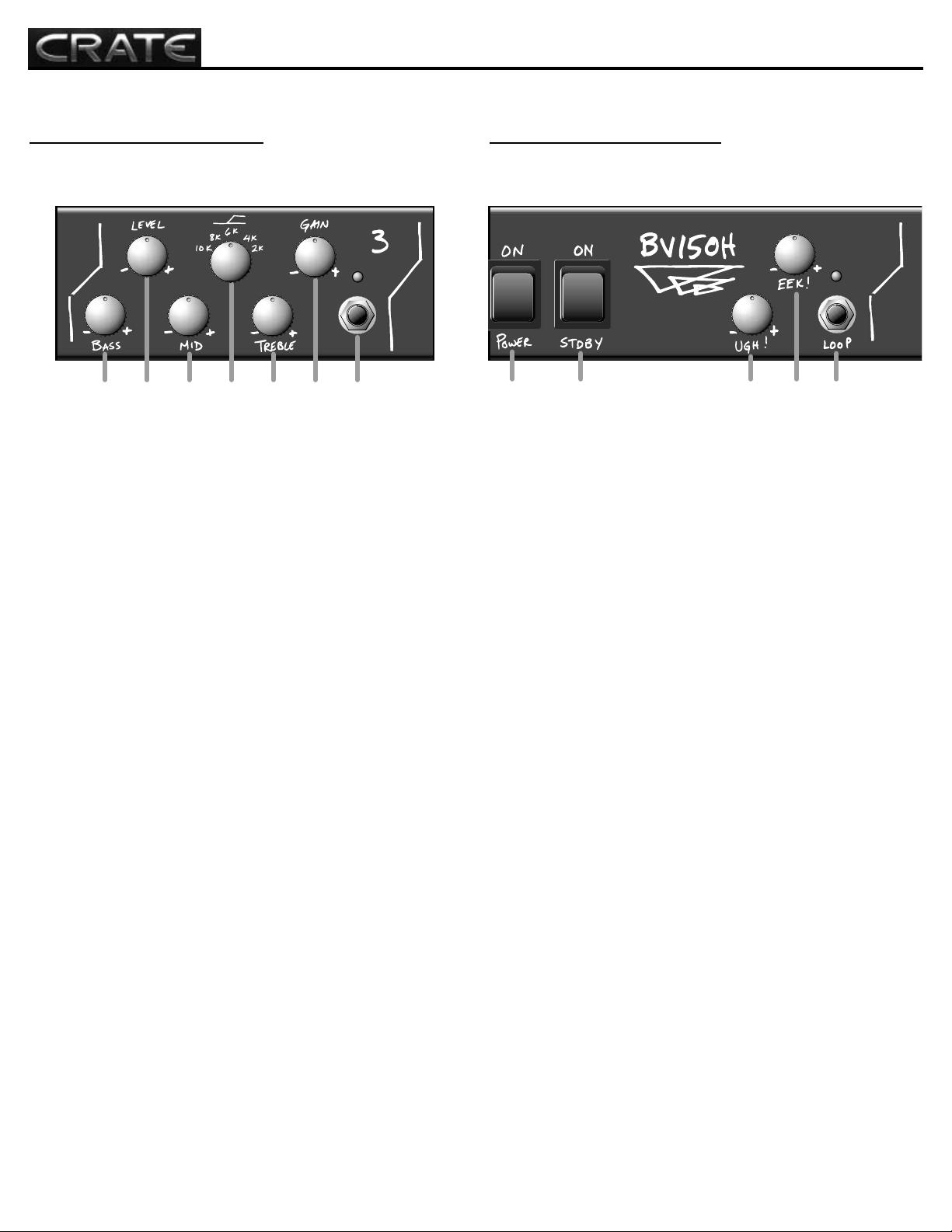
The Front Panel – Channel 3:
16. CH. 3 SELECT SWITCH: This switch, when activated, selects
Channel 3. The red LED above the switch illuminates when Channel
3 is selected. When the footswitch (#28, rear panel) is connected,
either the front panel select switches or the footswitch may be used
to select the active channel.
17. GAIN: Use this control to adjust the input gain for Channel 3.
With the control rotated counter clockwise, the resulting tones have a
puchy tube sound (perfect for “agressive” rhythm guitar). As you
rotate the control clockwise the tones take on serious overdrive distortion.
18. TREBLE: Use this control to adjust the high frequency output of
Channel 3. The Channel 3 Treble control provides 15dB of boost or
cut at the frequency selected by the High Freq Select switch (#19).
19. HIGH FREQ SELECT: Use this rotary switch to select the frequency for the High control (#18): 2kHz, 4kHz, 6kH, 8kHz or 10kHz.
20. MID: Use this control to adjust the mid frequency output of
Channel 3. The Channel 3 Mid control provides 20dB of boost or cut
at 1.2kHz.
21. LEVEL: Use this control to adjust the output level for Channel 3.
Use this control in conjunction with the Channel 3 Gain control (#17)
to achieve the desired sound for Channel 3.
22. BASS: Use this control to adjust the low frequency output of
Channel 3. The Channel 3 Bass control provides 18dB of boost or
cut at at 100Hz.
Effects Loop, Eek! and Ugh!:
23. LOOP SWITCH: This switch, when activated, engages the rear
panel Effects Loop (#33–37, rear panel). Ths blue LED above the
switch illuminates when the rear panel effects loop is engaged. When
the footswitch (#28, rear panel) is connected, either the front panel
Loop switch or the footswitch may be used to engage the effects
loop.
Note: This may also be used as an additional Boost switch – see
#37, page 5 for detailed information.
24: EEK!: Use this high frequency power amp damping control to
add definition and more of an edge to your sound. The Eek! control
is useful for compensating for acousticlly absorbent rooms or cabinets with overbearing low frequency resonance.
25: UGH!: Use this low frequency power amp damping control to
add control and shape the low end of your sound. The Ugh! control
tightens the low frequencies when rotated counter clockwise, giving
better control over the speaker cones. When this control is rotated
clockwise, the speaker cones are allowed to move more freely which
gives the sound more “thump.”
26: STANDBY SWITCH: Use this switch to activate the amplifier (top
of the switch depressed) or place the amplifier in the stand by mode
(bottom of the switch depressed). The amplifier should be in the
stand by mode during set breaks. This switch illuminates when the
amplifier is active.
Note: The Power switch (#27) must be turned on for at least ONE
MINUTE before turning on the Standby switch.
27. POWER SWITCH: Use this switch to turn the amplifier on (top of
the switch depressed) and off. This switch illuminates when the
amplifier is turned on.
22
20
18
16
21
19
17
27
26
24
23
22
21
20
19
18
17
16
27
26
252524
23
Page 3

5
BV150H Three Channel Guitar Amplifier
The Rear Panel:
28. FOOTSWITCH JACK: Use this jack to connect the BVFS4 four-
button footswitch to the amplifier for remote control of channel selection and effects loop on/off. Use the supplied MIDI cable for this connection. (A five-wire MIDI cable must be used for proper operation of
the footswitch.)
29. SPEAKER OUTPUT JACKS: Use these jacks to connect the
amplifier to your speaker cabient(s) by means of heavy duty (16GA
minimum) speaker cables.
Note: NEVER use the amplifier if it is not connected to a speaker
cabinet!
30. IMPEDANCE SWITCH: Use this switch to match the amplifier
impedance to match your speaker cabinet(s). Use the following
chart and be certain this switch is at the proper setting before turning
on the amplifier:
IMPEDANCE NUMBER OF TOTAL
OF CABINETS CABINETS IMPEDANCE
16 ohms 2 8 ohms
16 ohms 4 4 ohms
8 ohms 2 4 ohms
31. SLAVE OUT JACK: Use this jack to conenct the amplifier to a
second guitar amplifier, a powered monitor, or recording console.
The signal at this jack is an attenuated replica of the signal at the
Speaker Output jacks (#29).
Note: The Slave Out Level control (#32) must be fully counter clockwise before connection is made from the Slave Out jack to another
piece of equipment! SLOWLY rotate the Slave Out Level control
clockwise when setting the slave equipment levels.
32. SLAVE OUT LEVEL: Use this control to adjust the output level
of the signal at the Slave Out jack (#31).
33. EFFECTS LOOP SEND LEVEL: Use this control to adjust the
level of the signal at the Effects Loop Send jack (#34).
34. EFFECTS LOOP SEND: Use this jack to send a line level signal
to the input of an external effects processor.
35. EFFECTS LOOP SERIES/PARALLEL SWITCH: Use this switch
to configure the Effects Loop for series or parallel operation.
Experimenting with various effects will determine which setting provides the best results.
36. EFFECT LOOP RETURN JACK: Use this jack to return the signal from the output of an external effects processor into the effects
loop.
37. EFFECTS LOOP RETURN JACK: Use this control to adjust the
input level of the signal at the Effects Loop return jack (#36).
NOTE: The Effects Loop can also be used as a gain boost: connect a signal cable between the Send and Return jacks and use
the Effects Loop Send and Return Level controls (#33, 37) to
adjust the amount of signal boost - up to 6dB in series mode
and up to 9dB in parallel mode.
38. HUM BALANCE: Use this control to minimize the residual hum
in the amplifier. Use a small flatbalde screwdriver to gently rotate the
control until the hum is at a minimum. Allow the unit to fully warm up
and set all Level and Gain controls fully counterclockwise before
adjusting this control.
39. FUSE: The fuse protects the amplifier from voltage overload conditions. If the fuse fails, replace it only with the same size and type
of fuse. If the fuse fails repeatedly contact your Crate Service Center.
40. AC INLET JACK: Insert the female end of the power cord firmly
into this jack. The grounded power cord should only be plugged into
a grounded power outlet that meets all applicable electrical codes
and is compatible with the voltage, power and frequency requirements stated on the rear panel. Do not attempt to defeat the safety
ground connection!
28
29
32
34
38
40
The BVFS4 footswitch – select channels
and turn the effects loop on and off
with just a tap of your foot!
28
29
3030313132
333334
35353636373738
393940
Page 4

BV150H Three Channel Guitar Amplifier
BV150H
TECHNICAL SPECIFICA
TIONS:
Output Power Rating 150W RMS @ 5% THD, 4, 8, or 16Ω load, 120 VAC
Signal to Noise Ratio 75dB typical
Gain Channel 1 Channel 2 Channel 3
65dB 95dB 95dB
EQs Channel 1 Channel 2 Channel3
Low 24dB range @ 50Hz 20dB range @ 50Hz 18dB range @ 100Hz
Mid +10/-16dB @ EQ Switch setting 10dB range @ 750Hz 20dB range @ 1.2kHz
EQ Switch 300, 700, 1k, 1.5k or 3kHz +4~5dB @ 250, 500, 700 or 1kHz
2k, 4k, 6k, 8k or 10kHz
High 38dB range @ 5kHz 12dB range @ 2.5kHz 15dB range @ EQ Switch setting
EEK! 10dB above 5kHz
UGH! 12dB below 250Hz
PREAMP TUBES (8) 12AX7A
POWER TUBES (6) 6L6GC
POWER REQUIREMENTS 120VAC, 60Hz, 600VA
100/115VAC, 50/60Hz, 600VA
230VAC, 50/60Hz, 600VA
SIZE AND WEIGHT 30”W x 12”H x 10-1/2”D, 53 lbs.
www.crateamps.com
@2003 SLM Electronics, a division of St. Louis Music, Inc • 1400 Ferguson Avenue • St. Louis, MO 63133
47-489-01 • 071003
The BV150H is covered with a durable Tolex material: wipe it clean with a lint-free cloth. Never
spray cleaning agents onto the cabinet. Avoid abrasive cleansers which would damage the finish.
Crate continually develops new products, as well as improves existing ones. For this reason, the specifications and information in this manual are subject to change without notice.
Declaration Of Conformity
#__, Effective 01-01-2001
Manufacturer’s Name: SLM Electronics
Production Facility: 11880 Borman Drive, St. Louis, MO 63146, USA
Production Facility: 700 Hwy 202 W, Yellville, AR 72687, USA
Shipping Facility: 1400 Ferguson Ave., St. Louis, MO 63133, USA
Office Facility: 1400 Ferguson Ave., St. Louis, MO 63133, USA
Product Type: Audio Amplifier
Complies with the following Standards:
Safety: EN60065, E60065, C22.2, UL6500 and/or UL813
EMC: Directive 89/336/EEC, EN55103, EN55013, EN61000,
and/or FCC 47CFR 15B clA
Supplementary information provided by:
SLM Electronics - R & D Engineering
1901 Congressional Drive, St Louis, MO 63146, USA
Tel.: 314-569-0141, Fax: 314-569-0175
 Loading...