

Page 1
KXB50 Keyboard
Amplifier
User’s Guide
Page 2
Congratulations!
You are now the proud owner of the Crate KXB50 keyboard amplifier. This compact powerhouse features a 12” Crate Custom woofer and a Piezo tweeter housed in a ported tuned enclosure. Each of its two
input jacks has its own level control so you can mix your keyboard with another instrument or a high-Z
mic. The CD input jacks allows you to play along with your favorite music. The Insert jack allows you to
connect external effects to the to the amp and doubles as a line out jack to send a signal to a recorder,
mixing board or house PA. The headphones jack allows for private practice sessions.
The KXB50’s angled cabinet allows you to use it as an upward projecting floor monitor or stand it
upright like a conventional amplifier.
Like all Crate products, your KXB50 is designed by musicians, and built using only the best components. Extensive testing at the hands (and ears) of skilled technicians and musicians insures you that this
amplifier is the absolute best it can be.
In order to get the most out of your new amplifier, we strongly urge you to go over the information
contained in this manual before you begin playing.
And thank you
for choosing
KXB50 Keyboard Amplifier
IMPORTANT SAFETY INSTRUCTIONS
• READ, FOLLOW, HEED, AND KEEP ALL INSTRUCTIONS AND WARNINGS.
• DO NOT OPERATE NEAR ANY HEAT SOURCE AND DO NOT BLOCK ANY VENTILATION OPENINGS ON THIS APPARATUS. FOR
PROPER OPERATION, THIS UNIT REQUIRES 3” (75mm) OF WELL VENTILATED SPACE AROUND HEATSINKS AND OTHER AIR
FLOW PROVISIONS IN THE CABINET.
• DO NOT USE THIS APPARATUS NEAR SPLASHING, FALLING, SPRAYING, OR STANDING LIQUIDS.
• CLEAN ONLY WITH LINT-FREE DAMP CLOTH AND DO NOT USE CLEANING AGENTS.
• ONLY CONNECT POWER CORD TO A POLARIZED, SAFETY GROUNDED OUTLET WIRED TO CURRENT ELECTRICAL CODES AND
COMPATIBLE WITH VOLTAGE, POWER, AND FREQUENCY REQUIREMENTS STATED ON THE REAR PANEL OF THE APPARATUS.
• PROTECT THE POWER CORD FROM DAMAGE DUE TO BEING WALKED ON, PINCHED, OR STRAINED.
• UNPLUG THE APPARATUS DURING LIGHTNING STORMS OR WHEN UNUSED FOR LONG PERIODS OF TIME.
• ONLY USE ATTACHMENTS, ACCESSORIES, STANDS, OR BRACKETS SPECIFIED BY THE MANUFACTURER FOR
SAFE OPERATION AND TO AVOID INJURY.
• WARNING: TO REDUCE THE RISK OF ELECTRIC SHOCK OR FIRE, DO NOT EXPOSE THIS UNIT TO RAIN OR MOISTURE.
• SERVICE MUST BE PERFORMED BY QUALIFIED PERSONNEL.
• OUR AMPLIFIERS ARE CAPABLE OF PRODUCING HIGH SOUND PRESSURE LEVELS. CONTINUED EXPOSURE TO HIGH SOUND
PRESSURE LEVELS CAN CAUSE PERMANENT HEARING IMPAIRMENT OR LOSS. USER CAUTION IS ADVISED AND EAR PROTECTION IS RECOMMENDED IF UNIT IS OPERATED AT HIGH VOLUME.
CAUTION
RISK OF ELECTRIC SHOCK
DO NOT OPEN
WARNING: TO REDUCE THE RISK OF FIRE OR ELECTRIC
SHOCK, DO NOT EXPOSE THIS APPARATUS TO RAIN OR MOISTURE. TO REDUCE THE RISK OF ELECTRIC SHOCK, DO NOT
REMOVE COVER. NO USER-SERVICEABLE PARTS INSIDE.
REFER SERVICING TO QUALIFIED SERVICE PERSONNEL.
"IT IS NECESSARY FOR THE USER TO REFER TO THE INSTRUCTION MANUAL"
“ES NECESARIO QUE EL USUARIO SE REFIERA AL MANUAL DE INSTRUCCIONES.”
"REFERREZ-VOUS AU MANUAL D'UTILISATION"
EXPLANATION OF GRAPHICAL SYMBOLS:
EXPLICACION DE SIMBOLOS GRAFICOS:
EXPLICATION DES SYMBÔLES GRAPHIQUES:
"DANGEROUS VOLTAGE"
“VOLTAJE PELIGROSO”
"DANGER HAUTE TENSION"
=
=
PRECAUCION
RIESGO DE CORRIENTAZO
NO ABRA
PRECAUCION: PARA REDUCIR EL RIESGO DE INCENDIOS O DESCARGAS
ELECTRICAS, NO PERMITA QUE ESTE APARATO QUEDE EXPUESTO A LA
LLUVIA O LA HUMEDAD. PARA DISMINUOIR EL RIESGO DE CORRIENTAZO.
NO ABRA LA CUBIERTA. NO HAY PIEZAS ADENTRO QUE EL USARIO PUEDO
REPARAR DEJE TODO MANTENIMIENTO A LOS TECHNICOS CALIFICADOS.
ATTENTION
RISQUE D'ELECTROCUTION
NE PAS OUVRIR
ATTENTION: PROTÉGEZ CET APPAREIL DE LA PLUIE ET DE L'HUMIDITÉ
AFIN D'ÉVITER TOUT RISQUE D'INCENDIE OU D'ÉLECTROCUTION. POUR
REDUIRE D'ELECTROCUTION NE PAS ENLEVER LE COUVERCLE. AUCUNE
PIECE INTERNE N'EST REPRABLE PAR L'UTILISATEUR. POUR TOUTE
REPARATION, S'ADRESSER A UN TECHNICIEN QUALIFIE.
R
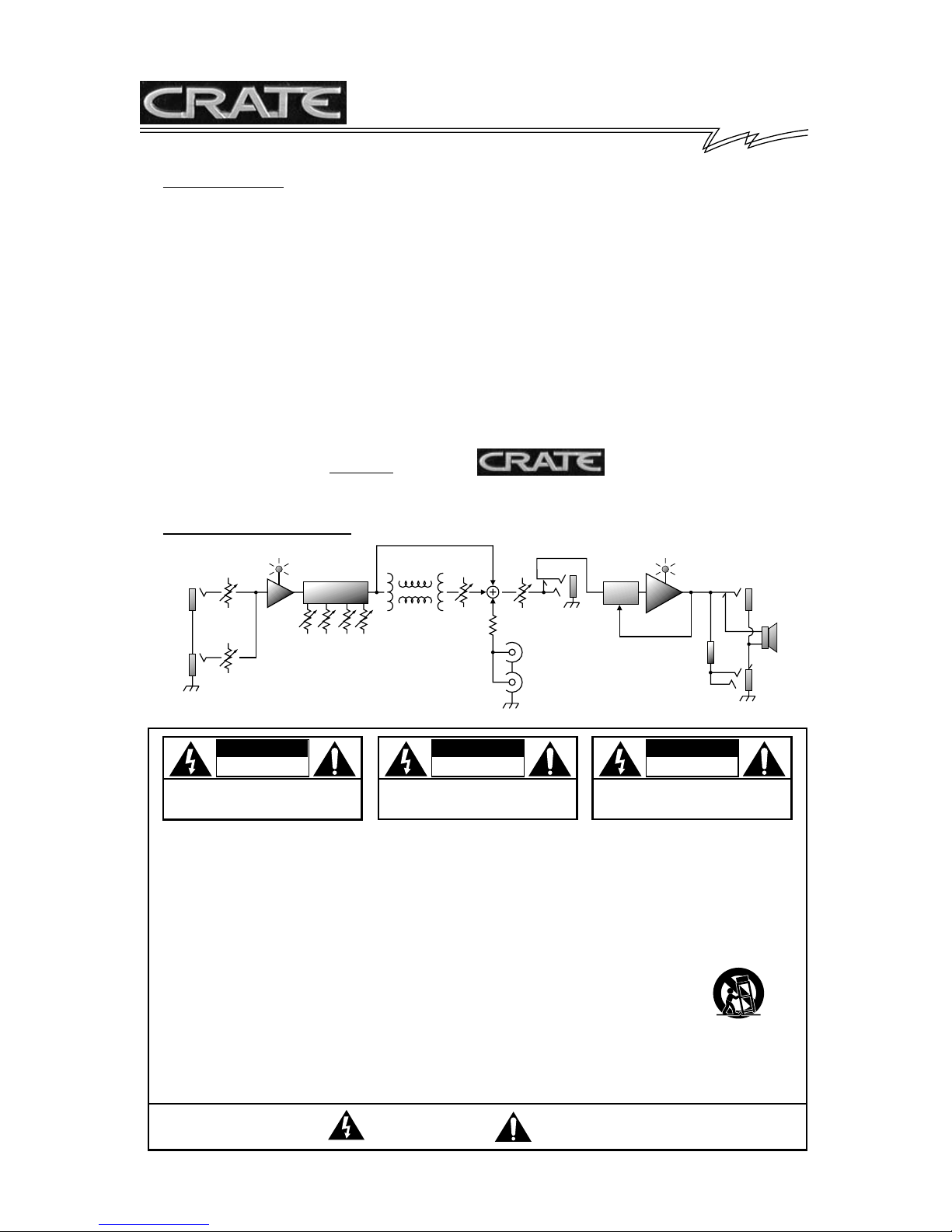
System Block Diagram:
PEAK
INPUTS
INST.
1
LEVEL 1 MASTER
INST.
2
LEVEL 2
EQ LIMITER
LO LO
MIDHIMID
HI
REVERB
REVERB
LEVEL
VOLUME
CD INPUT
INSERT
LIMIT
POWER
AMP
ATTENUATOR
EXT.
SPEAKE
HEAD
PHONES
Page 3

1 2 3 5 12 13 156 7 8 9 10 11 16 17144
1. INPUT 1: Use this 1/4” jack to connect your key-
board or other line level signal to the amplifier by
means of a shielded instrument cable. The signal
level at this jack is controlled by the Level 1 knob (#3).
2. INPUT 2: Use this 1/4” jack to connect your keyboard or other line level signal to the amplifier by
means of a shielded instrument cable. The signal
level at this jack is controlled by the Level 2 knob (#4).
3. LEVEL 1: Use this control to adjust the level of the
signal connected to the Input 1 jack (#1).
4. LEVEL 2: Use this control to adjust the level of the
signal connected to the Input 2 jack (#2).
5. PEAK: This LED illuminates when the input signal
level nears clipping. For the best signal to noise ratio,
adjust the Level controls until this LED flashes on
strong signal peaks.
6. LOW: Use this control to adjust the bass response
of the amplifier. Rotating the control counterclockwise
reduces the low frequency output. Rotating the control clockwise increases the low frequency output.
7. LO MID: Use this control to adjust the “thickness”
or “fatness” of the amplifier. Rotating the control counterclockwise reduces the lower midrange frequency
output. Rotating the control clockwise increases the
lower midrange frequency output.
8. HI MID: Use this control to adjust the clarity and
definition of the amplifier. Rotating the control counterclockwise reduces the upper midrange frequency
output. Rotating the control clockwise increases the
upper midrange frequency output.
9. HIGH: Use this control to adjust the high frequency
response of the amplifier. Rotating the control counterclockwise reduces the high frequency output.
Rotating the control clockwise increases the high frequency output.
10. REVERB: Use this control to adjust the amount of
reverberation added to the signal. With the control
fully counter clockwise, the signal is dry - no reverb
added. As you rotate the control clockwise the
amount of reverb added increases.
11. LEVEL: Use this control to adjust the overall output signal of the amplifier.
12. LIMIT: The KXB50 employs an internal limiter circuit to help prevent overdriving the output signal. This
LED illuminates when the limiter circuit is activated.
During normal playing conditions, this LED will flash
occasionally. If this LED remains illuminated, reduce
the level controls.
13. CD INPUT: Use these RCA jacks to connect the
output from a CD player or tape deck to the amplifier.
The signal at these jacks is combined into a mono signal which is sent to the internal power amp circuit.
Use the CD or tape player’s output level control to
adjust the signal for the proper mix with your instrument.
14. INSERT: Use this jack to connect external effects
to the amplifier. This is a stereo R/T/S 1/4” jack: ring =
line out, tip = line in, sleeve = ground. This jack can
also provide a line out signal - insert a mono T/S 1/4”
plug half way into the jack to obtain the signal. (This
will not interrupt the signal going into the internal
power amp.)
15. (HEADPHONES): Use this jack to connect
headphones to the amplifier. The internal speakers
are disconnected when this jack is used.
CAUTION: To avoid possible damage to your
hearing, do not use headphones for extended
periods of time at extremely loud levels.
16. ON: This LED illuminates when the amplifier is
turned on.
17. POWER: Use this switch to turn the amplifier on
(top of the switch depressed) and off (bottom of the
switch depressed).
18. POWER CORD (rear panel, not shown): The
grounded power cord should only be plugged into a
grounded power outlet that meets all applicable electrical codes and is compatible with the voltage, power,
and frequency requirements stated on the rear panel.
Do not attempt to defeat the safety ground connection.
KXB50 Keyboard Amplifier
Page 4
KXB50 Keyboard Amplifier
KXB50 TECHNICAL SPECIFICATIONS:
Output Power Rating 50 watts RMS @ 2% THD, 8 ohm load – 120 VAC line
Gain 50dB, tones at 12:00 @ 1kHz
Tone Control Range Low: 18dB @ 50Hz
Lo Mid: 21dB @ 150Hz
Hi Mid: 16dB @ 1kHz
High: 29dB @ 10kHz
Input Impedance 10k ohms
Maximum Signal Accepted 10 volts peak to peak
Insert Jack Line Output (Max): 2.5 volts peak to peak
Line Input (Max): 2.5 volts peak to peak
Speaker Size and Rating Crate Custom Design 12” w/ 1.5” voice coil,
30 oz. magnet; power handling 100 watts
Piezo Tweeter; power handling 150 watts
Cabinet Type Port Tuned enclosure
Input Power Requirements 120 VAC, 60Hz, 85VA
100/110 VAC, 50/60Hz, 85VA
230 VAC, 50/60Hz, 85VA
Cabinet Size and Weight 21.5” H x 17.5” W x 15” D, 39.5 lbs.
©2004 SLM ELECTRONICS, A DIVISION OF ST. LOUIS MUSIC, 1400 FERGUSON, ST. LOUIS, MO. U.S.A. 63133
P/N 47-385-01 • 100404
www. crateamps.com
Declaration of Conformity
Manufacturer’s Name: SLM Electronics
Corporate Headquarters: 1901 Congressional Drive, St. Louis, Missouri 63146
Primary Production Facility: 700 Hwy 202 W, Yellville, Arkansas, 72687
Product Type: Audio Amplifier
Products meet the regulations for compliance marking under:
ETL standards UL6500, UL60065, or UL813
CSA standards E60065 or C22.2 No.1-M90
CE safety standard EN60065
CE EMC standards EN55103 or EN55013 and EN61000
C-tick designation Level 2, ABN #56748810738, ARBN# N222
KETI standard K60065 (limited model approval)
Compliance Support Contact: SLM Electronics, Attn: R&D Compliance Engineer
1901 Congressional Drive, St Louis, Missouri, 63146 • Tel.: 314-569-0141, Fax: 314-569-0175
 Loading...