

Page 1
In order to achieve maximum performance from
your new Crate Audio Mixer we recommend that
you read this user’s guide prior to its use.
Powered Mixers
with
Digital Signal Processing
User’s Guide
for the
CRATE AUDIO
PM62S, PM82S
&
PM82T
Page 2
2
Congratulations.
You are now the proud owner of the compact and versatile Crate Audio PM62S/PM82S/PM82T powered mixer with Digital Signal Processing. In order to obtain the best performance from your new mixer,
please read this User’s Guide prior to its use.
And Thank You, from
Table of Contents:
Features . . . . . . . . . . . . . . . . . . . . . . . . . . . . . . . . . . . . . . . .3
The Mono Input Channels . . . . . . . . . . . . . . . . . . . . . . . . . .4
The Stereo Input Channels . . . . . . . . . . . . . . . . . . . . . . . . . .5
The Master Section . . . . . . . . . . . . . . . . . . . . . . . . . . . . . .6,7
The Rear Panel . . . . . . . . . . . . . . . . . . . . . . . . . . . . . . . . . .8
The DSP Section . . . . . . . . . . . . . . . . . . . . . . . . . . . . . . . . .9
System Block Diagram . . . . . . . . . . . . . . . . . . . . . . . . . .10,11
Technical Specifications . . . . . . . . . . . . . . . . . . . . .back cover
PM62S/PM82S/PM82T Powered Mixers
IMPORTANT SAFETY INSTRUCTIONS
• READ, FOLLOW, HEED, AND KEEPALL INSTRUCTIONS AND WARNINGS.
• DO NOT OPERATE NEAR ANY HEAT SOURCE AND DO NOT BLOCK ANY VENTILATION OPENINGS ON THIS APPARATUS. FOR PROPER OPERATION, THIS UNIT REQUIRES 3”
(75CM) OF WELL VENTILATED SPACE AROUND HEATSINKS AND OTHER AIR FLOW PROVISIONS IN THE CABINET.
• DO NOT USE THIS APPARATUS NEAR SPLASHING, FALLING, SPRAYING, OR STANDING LIQUIDS.
• CLEAN ONLY WITH LINT-FREE DAMP CLOTH AND DO NOT USE CLEANING AGENTS.
• ONLY CONNECT POWER CORD TO A POLARIZED, SAFETY GROUNDED OUTLET WIRED TO CURRENT ELECTRICAL CODES AND COMPATIBLE WITH VOLTAGE, POWER, AND
FREQUENCY REQUIREMENTS STATED ON THE REAR PANEL OF THE APPARATUS.
• PROTECT THE POWER CORD FROM DAMAGE DUE TO BEING WALKED ON, PINCHED, OR STRAINED.
• UNPLUG THE APPARATUS DURING LIGHTNING STORMS OR WHEN UNUSED FOR LONG PERIODS OF TIME.
• ONLY USE ATTACHMENTS, ACCESSORIES, STANDS, OR BRACKETS SPECIFIED BY THE MANUFACTURER FOR SAFE OPERATION AND TO AVOID INJURY.
• WARNING: TO REDUCE THE RISK OF ELECTRIC SHOCK OR FIRE, DO NOT EXPOSE THIS UNIT TO RAIN OR MOISTURE.
• SERVICE MUST BE PERFORMED BY QUALIFIED PERSONNEL.
• OUR AMPLIFIERS ARE CAPABLE OF PRODUCING HIGH SOUND PRESSURE LEVELS. CONTINUED EXPOSURE TO HIGH SOUND PRESSURE LEVELS CAN CAUSE PERMA-
NENT HEARING IMPAIRMENT OR LOSS. USER CAUTION IS ADVISED AND EAR PROTECTION IS RECOMMENDED IF UNIT IS OPERATED AT HIGH VOLUME.
CAUTION
RISK OF ELECTRIC SHOCK
DO NOT OPEN
WARNING: TO REDUCE THE RISK OF FIRE OR ELECTRIC SHOCK, DO NOT EXPOSE
THIS APPARATUS TO RAIN OR MOISTURE. TO REDUCE THE RISK OF ELECTRIC
SHOCK, DO NOT REMOVE COVER. NO USER-SERVICEABLE PARTS INSIDE. REFER
SERVICING TO QUALIFIED SERVICE PERSONNEL.
PRECAUCION
RIESGO DE CORRIENTAZO
NO ABRA
PRECAUCION: PARA REDUCIR EL RIESGO DE INCENDIOS O DESCARGAS ELECTRICAS, NO PERMITA QUE ESTE APARATO QUEDE EXPUESTO A LA LLUVIA O LA HUMEDAD. PARA DISMINUOIR EL
RIESGO DE CORRIENTAZO. NO ABRA LA CUBIERTA. NO HAY PIEZAS ADENTRO QUE EL USARIO
PUEDO REPARAR DEJE TODO MANTENIMIENTO A LOS TECHNICOS CALIFICADOS.
ATTENTION
RISQUE D'ELECTROCUTION
NE PAS OUVRIR
ATTENTION: PROTÉGEZ CET APPAREIL DE LA PLUIE ET DE L'HUMIDITÉ AFIN D'ÉVITER TOUT
RISQUE D'INCENDIE OU D'ÉLECTROCUTION. POUR REDUIRE D'ELECTROCUTION NE PAS ENLEVER
LE COUVERCLE. AUCUNE PIECE INTERNE N'EST REPRABLE PAR L'UTILISATEUR. POUR TOUTE
REPARATION, S'ADRESSER A UN TECHNICIEN QUALIFIE.
"IT IS NECESSARY FOR THE USER TO REFER TO THE INSTRUCTION MANUAL"
“ES NECESARIO QUE EL USUARIO SE REFIERA AL MANUAL DE INSTRUCCIONES.”
"REFERREZ-VOUS AU MANUAL D'UTILISATION"
EXPLANATION OF GRAPHICAL SYMBOLS:
EXPLICACION DE SIMBOLOS GRAFICOS:
EXPLICATION DES SYMBÔLES GRAPHIQUES:
"DANGEROUS VOLTAGE"
“VOLTAJE PELIGROSO”
"DANGER HAUTE TENSION"
=
=
Page 3

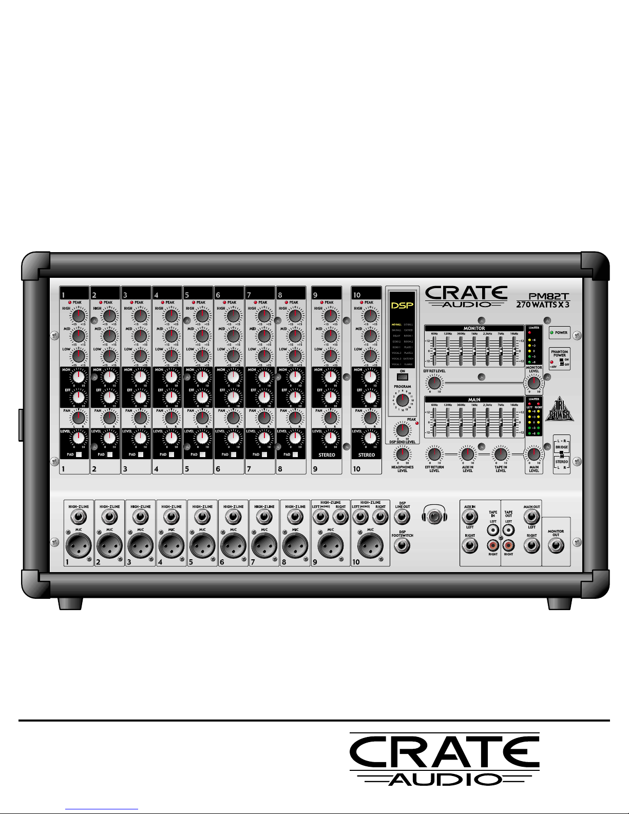
Features:
The Input Channels:
• Peak LEDs for optimum level settings
• Three bands of equalization
• Monitor, effects, and pan controls
• Output level controls
• Pad switch (mono channels) to accommodate “hot” signals
• XLR balanced low impedance mic input jacks
• 1/4” balanced high-Z line input jacks
The Master Section:
• Tri-Power! Three internal power amplifiers (PM82T only) - one for the monitor, two for the
main speaker outputs
• Two internal power amplifiers (PM62S, PM82S) for the main speaker outputs
• Built in Limiter to prevent overdriving the amplifiers
• Two 7-band graphic EQs - one for monitor, one for mains
• Five-step LED displays with Limiter indicators for monitoring the output signals
• Effects send and return controls
• Switchable phantom power (+48V)
• 16-Program Digital Signal Processor (DSP) with on/off switch
• Footswitch jack for remote control of DSP on/off
• Headphones jack with level control
• DSP line out/aux in jacks for external effects
• Tape in and tape out jacks for recording and play back
• Main and monitor line out jacks
3
PM62S/PM82S/PM82T Powered Mixers
This equipment has been tested and found to comply with the limits for a Class B digital device, pursuant
to part 15 of the FCC Rules. These limits are designed to provide reasonable protection against harmful
interference in a residential installation. This equipment generates, uses and can radiate radio frequency energy and, if not installed and used in accordance with the instructions, may cause harmful interference to radio communications. However, there is no guarantee that interference will not occur in a particular installation. If this equipment does cause harmful interference to radio or television reception,
which can be determined by turning the equipment off and on, the user is encouraged to try to correct
the interference by one or more of the following measures:
• Reorient or relocate the receiving antenna.
• Increase the separation between the equipment and the receiver.
• Connect the equipment into an outlet on a circuit different from that to which the receiver is connected.
• Consult the dealer or an experienced radio/TV technician for help.
Changes or modifications to this device not expressly approved by SLM Electronics could void the user’s
authority to operate the equipment under FCC rules.
Page 4
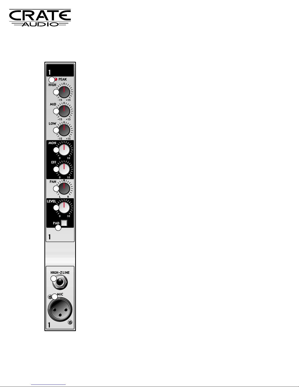
1. PEAK LED: This LED illuminates when the input signal
nears clipping. During normal operation, this LED will flash
on strong signal peaks. If the LED remains illuminated,
depress the Pad switch (#9) and/or reduce the level of the
signal connected to the input jack (#10,11).
2. HIGH: Use this control to adjust the high frequency level
for the channel.
3. MID: Use this control to adjust the midrange frequency
level for the channel.
4. LOW: Use this control to adjust the low frequency level for
the channel.
5. MON: Use this control to adjust the amount of the channel’s signal sent to the monitors.
6. EFFECT: Use this control to adjust the amplitude of the
internal DSP effect (or external effects, if used) to be
applied to the channel’s signal.
7. PAN: Use this control to adjust the left-to-right balance of
the channel’s signal.
8. LEVEL: Use this control to adjust the channel’s output signal level.
9. PAD: Use this switch to accommodate “hot” input signals.
(Signals too strong to allow a useful setting of the gain control without causing the Peak LED - #1- to remain illuminated.) Depress this switch to engage the 20dB pad, thereby
reducing the input signal’s level to a more useable range.
10. HIGH-Z LINE: Use this jack to connect the output signal
from a high impedance microphone or a line level signal
(such as an instrument, rhythm machine, tape deck, etc.)
to the mixer by means of a shielded cable terminated with
a male 1/4” plug. Tip = “+,” ring = “–,” sleeve = shield.
11. MIC: Use this jack to connect the output signal from a low
impedance microphone to the mixer by means of a shielded cable terminated with a male XLR plug. Pin 2 = “+,” pin
3 = “–,” pin 1 = shield.
The Mono Input Channels:
4
PM62S/PM82S/PM82T Powered Mixers
1
2
3
4
5
10
11
6
7
8
9
Page 5

12. PEAK LED: This LED illuminates when the input
signal nears clipping. During normal operation, this
LED will flash on strong signal peaks. If the LED
remains illuminated, reduce the level of the signal
connected to the input jack (#20,21).
13. HIGH: Use this control to adjust the high frequency
level for the channel.
14. MID: Use this control to adjust the midrange frequency level for the channel.
15. LOW: Use this control to adjust the low frequency
level for the channel.
16. MON: Use this control to adjust the amount of the
channel’s signal sent to the monitors.
17. EFFECT: Use this control to adjust the amount of
the internal DSP effect (or external effects, if used)
to be applied to the channel’s signal.
18. PAN: Use this control to adjust the left-to-right balance of the channel’s signal.
19. LEVEL: Use this control to adjust the channel’s output signal level.
20. HIGH-Z LINE: Use these jacks to connect the output signal from a stereo line level source (such as a
stereo instrument, rhythm machine, tape deck, etc.)
to the mixer by means of shielded cables terminated with male 1/4” plugs. Tip = “+,” ring = “–,” sleeve
= shield.
The LEFT
(MONO) jack serves as a mono input that
will feed a single input signal to both the left and
right channels. For stereo signals, use the LEFT
(MONO)
jack as the left channel input and the RIGHT
jack as the right channel input.
21. MIC: Use this jack to connect the output signal from
a low impedance microphone to the mixer by
means of a shielded cable terminated with a male
XLR plug. Pin 2 = “+,” pin 3 = “–,” pin 1 = shield.
The Stereo Input Channels:
5
PM62S/PM82S/PM82T Powered Mixers
12
13
14
15
16
21
17
18
19
20
Page 6

The Master Section:
6
PM62S/PM82S/PM82T Powered Mixers
22. DSP ON: This switch, when depressed, acti-
vates the internal digital signal processor.
23. PROGRAM: Use this rotary switch to select
the desired digital effect. The name of the
selected effect illuminates on the DSP display
panel (located above the On switch, #22). A
brief description of the DSP effects is provided on page 9.
24. MONITOR: Use this seven band graphic
equalizer to shape the monitor output signal.
This is useful for feedback control and to
compensate for room acoustics.
25. LIMITER/LED METER: The mixer employs
internal limiter circuits to prevent overdrive
distortion from being reproduced by the
amplifiers. The Limiter LED illuminates when
the monitor amplifier’s internal limiter circuit
is activated.
The five-step LED display directly below the
Limiter LED indicates the level of the monitor’s output signal.
26. POWER LED: This LED will illuminate when
the mixer is turned on. (The power switch is
located on the mixer’s rear panel - see #51,
page 9.)
27. PHANTOM POWER: This switch, when at the
“on” position, applies +48 volts DC to pins 2
and 3 of each channel’s XLR MIC input jack.
The adjacent LED illuminates when the phantom power is turned on.
28. EFF RET LEVEL: Use this control to adjust the
level of the internal DSP applied to the signal at
the Monitor Out jack (#47) and the Speakers Monitor jacks (PM82T only - #50, page 9).
29. MONITOR LEVEL: Use this control to adjust
the overall level of the signal at the Monitor
Out jack (#47) and the Speakers - Monitor jacks
(PM82T only - #50, page 9).
30. MAIN: Use this seven band graphic equalizer
to shape the main output signal. This is useful for feedback control and to compensate for
room acoustics. Each slider controls both
main outputs simultaneously (see Speakers Left / Right, #48 on page 9).
22
28
23
33
24
30
25
26
27
29
31
32
34
40
41
35 36 37
42
43
44 45
38
46
47
39
Page 7

The Master Section (con’t):
31. LIMITER/LED METER: The mixer employs inter-
nal limiter circuits to prevent overdrive distortion
from being reproduced by the amplifiers. The
Limiter LEDs illuminate when either of the main
amplifiers’ internal limiter circuits are activated.
The two sets of five-step LED displays directly
below the Limiter LEDs indicate the levels of the
left and right main’s output signal.
32. DSP SEND LEVEL: Use this control to adjust the
level of signal at the DSP Line Out jack (#40) and
to the internal DSP processor.
33. PEAK: This LED illuminates when the DSP signal
level nears clipping. During normal operation, this
LED will flash on strong signal peaks. If the LED
remains illuminated, reduce the DSP Send Level
control (#32).
34. HEADPHONES LEVEL: Use this control to adjust
the level of the signal at the (Headphones) jack
(#42).
35. EFF RETURN LEVEL: Use this control to adjust
the level of the internal DSP applied to the Tape
Out jacks (#45), the Main Out Left / Right jacks
(#46), and the Speakers - Left / Right jacks (#48,
page 9).
36. AUX IN LEVEL: Use this control to adjust the level
of the signal applied to the Main outputs from the
Aux In - Left / Right jacks (#43).
37. TAPE IN LEVEL: Use this control to adjust the
level of the signal from the Tape In - Left / Right
jacks (#44) applied to the Main outputs.
38. MAIN LEVEL: Use this control to adjust the overall
level of the signal at the Main Out Left / Right jacks
(#46) and the Speakers - Left / Right jacks (#48,
page 9).
39. BRIDGE/STEREO: Use this switch to determine
whether the main power amplifiers are bridged
together for a single output signal (at the up position) or work separately for a stereo output signal
(at the down position).
40. DSP LINE OUT: Use this jack to send an output
signal to an external effects device. Connect this
jack to the effect’s input jack by means of a shielded signal cable.
41. DSP FOOTSWITCH: Use this jack to connect a
footswitch to the mixer for remote on/off control of
the internal DSP. The footswitch must be a normally open / momentarily closed type (such as the
Crate model #FSIU). The wiring for the footswitch
is shown at the bottom of this page.
42. (HEADPHONES): Use this jack to connect a
pair of stereo headphones to monitor the main output signals. The level of the signal is adjusted by
the Headphones Level control (#34).
43. AUX IN - LEFT / RIGHT: Use these jacks to connect an external effects device’s output signal or to
feed another mixer’s signal into the mixer. These
jacks are post-input channel, pre-eq and pre-power
amp, and the signal levels are adjusted by the Aux
In Level control (#36).
44. TAPE IN - LEFT / RIGHT: Use these jacks to connect the output signal from a tape deck or CD player to the mixer. The signal level is adjusted by the
Tape In Level control (#37).
45. TAPE OUT - LEFT / RIGHT: Use these jacks to
connect the output of the mixer to a tape recorder.
These jacks are pre-eq, pre-master, and their signal level is adjusted by the channel Level controls
(#8, #19).
46. MAIN OUT - LEFT / RIGHT: Use these jacks to
connect the mixer’s pre-amplified output signal to
an external power amplifier, recording console, or
to the Aux In jack of another Crate powered mixer.
48. MONITOR OUT: Use this jack to send a pre-amplified signal to an auxiliary monitor amplifier (or powered monitor).
Wiring for the DSP footswitch (#41):
7
PM62S/PM82S/PM82T Powered Mixers
Page 8

48. SPEAKERS - LEFT / RIGHT: Stereo Mode
Only! (See #39, front panel master sec-
tion.) Use these jacks to connect the mixer
to your left and right main speakers. Observe
the four ohm minimum load rating and the
additional speaker information printed on the
rear of the mixer.
49. SPEAKERS - BRIDGE: Bridge Mode
Only! (See #39, front panel master sec-
tion.) Use this jack to connect the mixer to
your main speakers. Observe the eight ohm
minimum load rating and the additional
speaker information printed on the rear of
the mixer.
50. SPEAKERS - MONITOR (PM82T only):
Use these jacks to connect the mixer to your
monitor speakers. Observe the four ohm
minimum load rating and the additional
speaker information printed on the rear of
the mixer.
51. POWER: Use this switch to turn the mixer
on (switch de-pressed) and off (switch in the
out position). The front panel Power LED
(#26) illuminates when the mixer is on.
52. AC LINE CORD: The grounded power cord
should only be plugged into a grounded
power outlet that meets all applicable electrical codes and is compatible with the voltage, power and frequency requirements
stated on the rear panel. Do not attempt to
defeat the safety ground connection!
The Rear Panel:
8
PM62S/PM82S/PM82T Powered Mixers
“Class 2 Wiring” for all other terminals
provided the audio output power exceeds
10 W per channel under normal operating
conditions or the apparatus is intended to
be installed or interconnected in the field
by a skilled person.
MAXIMUM OUTPUT 270 WATTS PER CHANNEL @ 4Ω
BA
48 49 48
POWER
51
ON
52
OFF
100V 50/60Hz, 10A
120V 60Hz, 10A
230V 50Hz, 6.3A
240V 50Hz, 6.3A
SPEAKERS
A and B:
A or B:
BRIDGED:
• CLASS 2 WIRING •
16Ω LOAD / 8Ω MINIMUM
8Ω LOAD / 4Ω MINIMUM
16Ω LOAD / 8Ω MINIMUM
BRIDGE LEFTRIGHT
B A
B
A
50
MONITOR
CAUTION:
DO NOT CONNECT TO A OR B
WHEN IN BRIDGED MODE.
WARNING:
THIS AMPLIFIER IS CAPABLE OF
PRODUCING SOUND PRESSURE LEVELS
IN EXCESS OF 110dB. CONTINUED
EXPOSURE TO HIGH SOUND PRESSURE
LEVELS CAN CAUSE PERMANENT
HEARING IMPAIRMENT OR LOSS. USER
CAUTION IS ADVISED AND EAR
PROTECTION IS RECOMMENDED WHEN
PLAYING AT HIGH VOLUMES. THE U.S.
GOVERNMENT HAS ESTABLISHED
ACCEPTABLE NOISE EXPOSURE LEVELS.
REFER TO THESE GUIDELINES FOR
ALLOWABLE EXPOSURE TIMES.
CAUTION: CHASSIS SURFACE HOT.
ATTENTION: SUPERFACIE DE CHASSIS EST CHAUDE.
H
O
T
Page 9
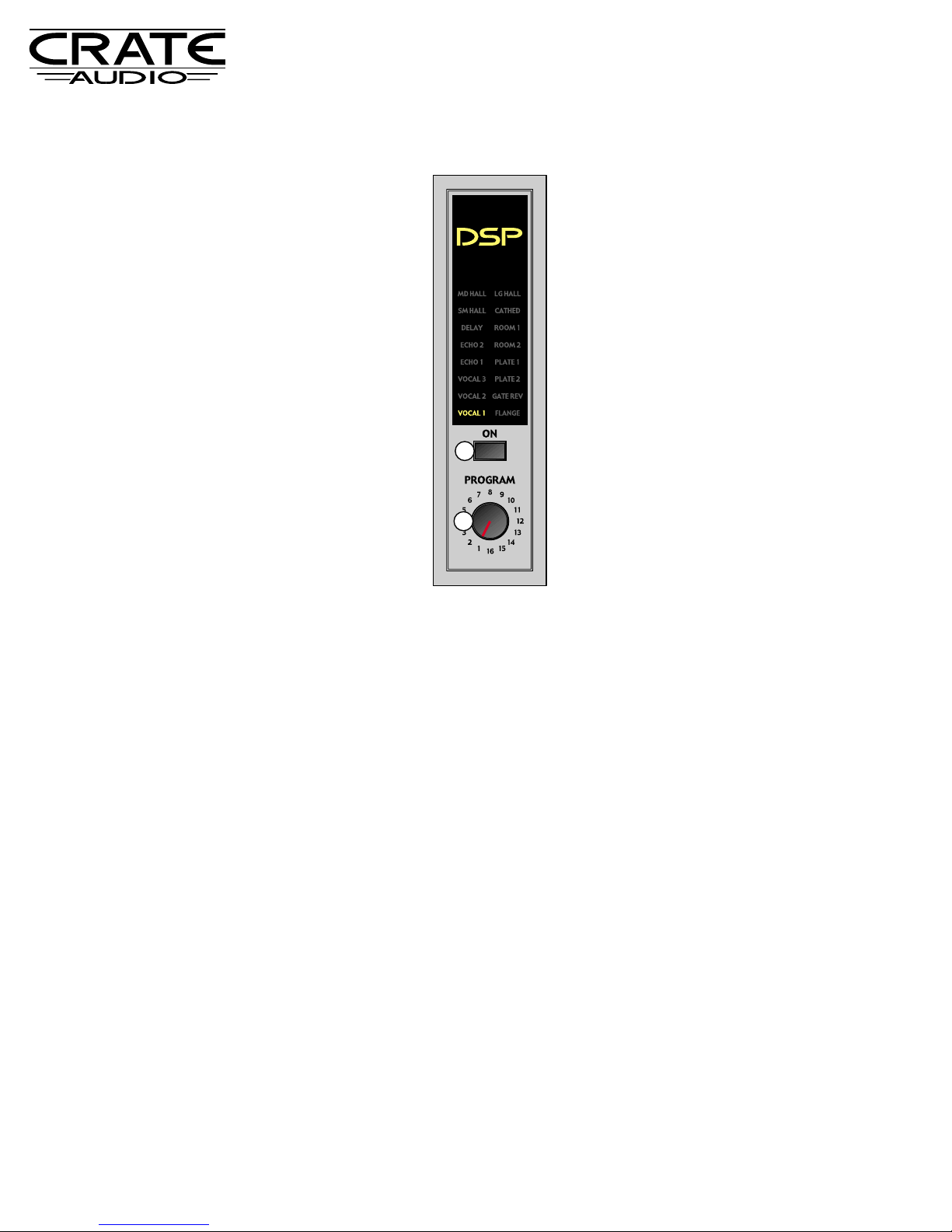
The DSP Section:
PROGRAM # NAME DESCRIPTION
1 VOCAL 1 slight chorus, short slapback delay, medium hall reverb
2 VOCAL 2 chorus with large hall reverb
3 VOCAL 3 doubler, short flange, large plate reverb
4 ECHO 1 125 ms echo with long regeneration
5 ECHO 2 250 ms echo with short regeneration
6 DELAY 125 ms delay
7 SM HALL small hall reverb
8 MD HALL medium hall reverb with early reflections
9 LG HALL large hall reverb
10 CATHED large saturated reverb - similar to church/cathedral
11 ROOM 1 small tight room reverb
12 ROOM 2 medium room reverb
13 PLATE 1 small plate reverb
14 PLATE 2 large plate reverb
15 GATEREV gated reverb (medium hall)
16 FLANGE large deep flange, slow rate, low resonance
9
PM62S/PM82S/PM82T Powered Mixers
Use the DSP
Program control
(#23) to select
one of the sixteen digital
effects - the
selected effect
illuminates on the
display panel.
(The effects are
only active when
the DSP On
switch - #22 - is
depressed.)
The chart below lists each of the sixteen digital effects by its Program number, its name (as indicated on the DSP display
panel), and a brief description of the effect:
22
23
Page 10

System Block Diagram:
10
PM62S/PM82S/PM82T Powered Mixers
MONO CHANNELS:
PHANTOM
POWER
+48V
MIC
PAD
MON
PEAK
LEFTLEFT
RIGHTRIGHT
EFFECT
MONITORMONITOR
HIGH-Z
LINE
STEREO CHANNELS:
PHANTOM
POWER
+48V
MIC
HIGH-Z
LINE
LEFT
(MONO)
HIGH-Z
LINE
RIGHT
LOW MID HIGH
LEVEL
LMH
LOW
MID HIGH
EFF
LEVEL
LEVEL
PAN
PEAK
MON
PAN
EFFECT
MON
PAN
EFFECT
AUX IN
LEFT
TAPE IN
LEFT
AUX IN
RIGHT
TAPE IN
RIGHT
TAPE IN
LEVEL
TAPE IN
LEVEL
AUX IN
LEVEL
AUX IN
LEVEL
EFFECT
Page 11

11
System Block Diagram (con’t):
LIMITER/
LED
DISPLAY
INV
BRIDGE
STEREO
3
2
1
SPEAKERS
BRIDGE
SPEAKERS
A
LEFT
POWER
AMP
RIGHT
POWER
AMP
SPEAKERS
B
SPEAKERS
A
SPEAKERS
B
HEAD-
PHONES
HEAD-
PHONE
LEVEL
TAPE
OUT
LEFT
TAPE
OUT
RIGHT
MAIN
OUT
LEFT
MAIN
OUT
RIGHT
7-BAND
GRAPHIC
EQ
7-BAND
GRAPHIC
EQ
DSP LINE
OUT
DSP FOOT-
SWITCH
DSP
ON
PROGRAM
LIMITER/
LED
DISPLAY
DSP SEND
LEVEL
MONITOR
LEVEL
7-BAND
GRAPHIC EQ
MONITOR
OUT
SPEAKERS
MONITOR A
SPEAKERS
MONITOR A
LIMITER/
LED
DISPLAY
MONITOR
EFF RET
LEVEL
MAIN EFF
RETURN
LEVEL
MAIN EFF
RETURN
LEVEL
MONITOR
POWER
AMP
PM82T ONLY
PEAK
PROGRAM
INDICATOR
MAIN
LEVEL
MAIN
LEVEL
PM62S/PM82S/PM82T Powered Mixers
Page 12

www.crateaudio.com
©2004 SLM Electronics, Inc. • A Division of St. Louis Music, Inc.
1400 Ferguson Avenue • St. Louis, MO 63133
18-681-02 • 101304
PM62S/PM82S/PM82T Powered Mixers
Technical Specifications
Due to ongoing product development and improvement, the specifications contained herein are subject to change without notice.
MAXIMUM VOLTAGE GAIN 87dB Mic In to Power Amp Out Main 1, 2 and Monitor
(PAD OFF) 59dB Mic In to Main Out, Monitor Out
64dB Mic In to Effect Out
47dB Mic In to Rec Out
47dB Line In to Main Out, Monitor Out
26dB Aux In to Main Out, Left (Mono), Right
17dB Stereo Left/Mono to Main
INPUT CHANNEL EQUALIZATION ±15dB Maximum
High: 12kHz (shelving); Mid: 2kHz (peaking); Low: 80Hz (shelving)
FREQUENCY RESPONSE +1/-3dB, 20Hz-20kHz @ 1W output into 8 ohms (Power Amp Out)
+1/-3dB, 20Hz-20kHz @ +4dB output into 10k ohms (Main Out, Monitor Out, Effects Send)
MAXIMUM OUTPUT POWER PM62S, PM82S: 2 X 400W/4 ohms @ 0.5% THD @ 1kHz
PM82T: 3 X 270W/4 ohms @ 0.5% THD @ 1kHz
TOTAL HARMONIC DISTORTION <0.3% @ 20Hz-20kHz, 100W output into 4 ohms (Power Amp Out)
<0.3% @ 20Hz-20kHz, +14dB output into 10k ohms (Main Out, Monitor Out, Effects Send)
HUM AND NOISE -115dB equivalent input noise, -53dBv residual output noise
(Average, Rs=150Ω) (Power Amp Out)
(with 20Hz-20kHz BPF) -74dBv residual output noise (Main Out, Monitor Out, Effects Send)
-71dBv (75dB S/N) (Main Out, Monitor Out) All channel Level controls at minimum
-67dBv (72dB S/N) (Main Out, Monitor Out) One channel Level control at maximum
-73dBv (77dB S/N) Effects Send All channel Level controls at minimum
-62dBv (66dB S/N) Effects Send One channel Level control at maximum
CHANNEL CROSSTALK @ 1kHz < -90dB
GRAPHIC EQUALIZER +/-12dB @ 60Hz, 120Hz, 360Hz, 1kHz, 2.5kHz, 7kHz, 16kHz
INTERNAL DIGITAL EFFECT 16 programs
PHANTOM POWER +48V is supplied to electrically balanced inputs for powering condenser microphones via 6.8kΩ current
limiting/isolating resistors
LIMITER LED ON Output Level: +34dBv
FOOT SWITCH DSP On/Off
POWER CONSUMPTION 1500W
SIZE AND WEIGHT PM62S: 19” (483mm) W x 13” (330mm) H x 11” (279mm) D; 49 lbs (22kg)
PM82S: 21.25” (540mm) W x 13” (330mm) H x 11” (279mm) D; 51 lbs (23kg)
PM82T: 21.25” (540mm) W x 13” (330mm) H x 11” (279mm) D; 52 lbs (24kg)
 Loading...