

Page 1
Page 2

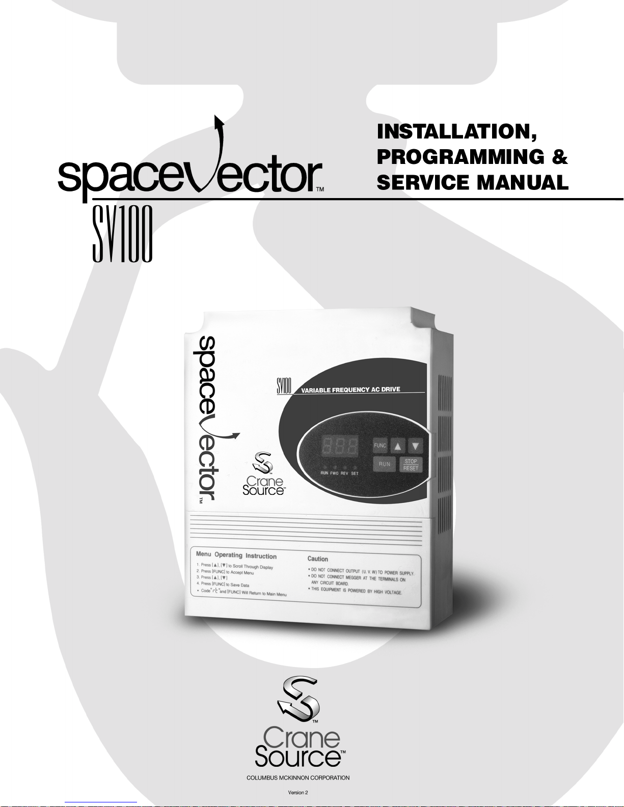
SpaceV ector™ Variable Frequency Drives
Congratulations on the purchase of a SpaceV ector™ SV100 Series drive. This is the most advanced drive
on the market today specifically designed and programmed for the overhead material handling industry by
the leader in the industry, Columbus McKinnon Corporation.
SpaceV ector™ drives have many advantages and features to meet the very specific and demanding needs
of the crane and hoist industry. Features such as:
· An energy efficient drive, resulting in less heating of the motor.
· Cooler running motors last longer, saving on downtime and maintenance costs.
· Efficient utilization produces more torque, resulting in better load control.
· Reduced motor harmonics, which improve motor performance and lengthen life.
· Easy macro quick set programming for faster start-up and servicing.
· Plain English programming and service manual saves time.
IMPORTANT! PLEASE READ!
Before proceeding any further, please read the following important information regarding the drive and its
proper handling and use:
· Please read this manual completely before working with the drive.
· The drive operates on and contains high voltage that can cause electric shock resulting
in personal injury or loss of life. Handle the drive with the same care and caution as
all other high voltage electrical components.
· Be sure to disconnect all AC input power to the drive before servicing. Lock and tag
the main switch in the de-energized position per ANSI Z 244.1.
· Wait at least 3 minutes after disconnecting the AC input power to the drive. If the bus
capacitor discharge circuit fails, high voltage can remain in the drive for a period of
time after the AC power is disconnected.
· Do not perform high voltage tests such as Megger testing.
· Only qualified personnel should perform service.
· Ensure unit is properly grounded.
· Disconnect drive before performing any welding on the bridge crane structure. Do
not weld the hook, to the hook or to a load suspended from the hook.
On the following pages are specification and selection tables for the drives and dynamic braking resistors.
Please check to insure you have the proper equipment for your application.
2
Page 3

SV100
Table Of Contents
Introduction...........................................................................................................2
Chapter 1: Installation
Section 1.1: Inspection of Drive.........................................................................6-9
Section 1.2: Mounting the Drive.....................................................................10-14
Section 1.3: Wiring the Drive .........................................................................15-20
Chapter 2: Start Up Programming
Section 2.1: Keypad Layout................................................................................ 22
Section 2.2: Keypad Operation
2.2.1: Definitions .................................................................................... 23
2.2.2: Moving through the Program...................................................23-29
2.2.3: Changing Control from Pendant to Keypad - Jog Mode ..............30
Section 2.3: Initial Setup Programming
2.3.1: Programming for a Specific Application..................................31-32
2.3.2: Programming the Speed Selection .........................................33-34
2.3.3: Drive Operation Checks.............................................................. 35
Chapter 3: Programming
Section 3.1 Passwords and Group Access Levels
3.1.1: Passwords................................................................................... 38
3.1.2: Entering a Password....................................................................38
3.1.3: Changing Passwords...................................................................38
Section 3.2 Programming Function Data ......................................................41-42
Section 3.3 Establishing Motor Parameters ..................................................43-44
Chapter 4: Troubleshooting
Section 4.1 Monitoring Current and Error Codes
4.1.1 Monitoring Current During Operation in
T able 4.1.1: Error Code T roubleshooting Table..................................47-48
User Level.......................46
Section 4.2 Problem Flo w Cha rts..................................................................49-52
Section 4.3 Testing Power Components.............................................................53
Section 4.4 Pushbutton Pendant Test.................................................................54
3
Page 4

Chapter 5: Function Code Information
Section 5.1 User Level Functions .................................................................57-59
Section 5.2 Service Level Functions.............................................................60-70
Section 5.3 Advanced Level Functions.........................................................71-88
Chapter 6: Maintenance
Section 6.1 Maintenance .................................................................................... 90
Section 6.2 Precaution ....................................................................................... 90
Section 6.3 Routine Inspection...........................................................................90
Section 6.4 Visual Inspection ............................................................................. 90
Appendix................................................................................................91-93
4
Page 5

Chapter 1: Installation
Section 1.1: Inspection of Drive
Section 1.2: Mounting the Drive
Section 1.3: Wiring the Drive
5
Page 6
Section 1.1: Inspection of the Drive
WARNING
Working in or near exposed energized electrical equipment
presents a danger of electric shock.
To Avoid Injury:
• Disconnect and lockout power to the drive per ANSI Z
244.1
• Wait 3 minutes after disconnecting power for capacitor
discharge before entering drive.
1. Inspect the drive for any physical damage that may have occurred during its
shipment. If any parts of the drive are missing or damaged, contact your
SpaceV ector™ distributor immediately.
2. V erify the nameplate of the SV100 drive. V erify that the drive part number matches
your order and packing slip.
3. Verify that the Dynamic Braking Resistor part number matches your order and packing slip.
4. If there are any questions reference Tables 1.1.1, 1.1.2, 1.1.3, 1.1.4 for Drive and
Resistor specifications.
6
Page 7
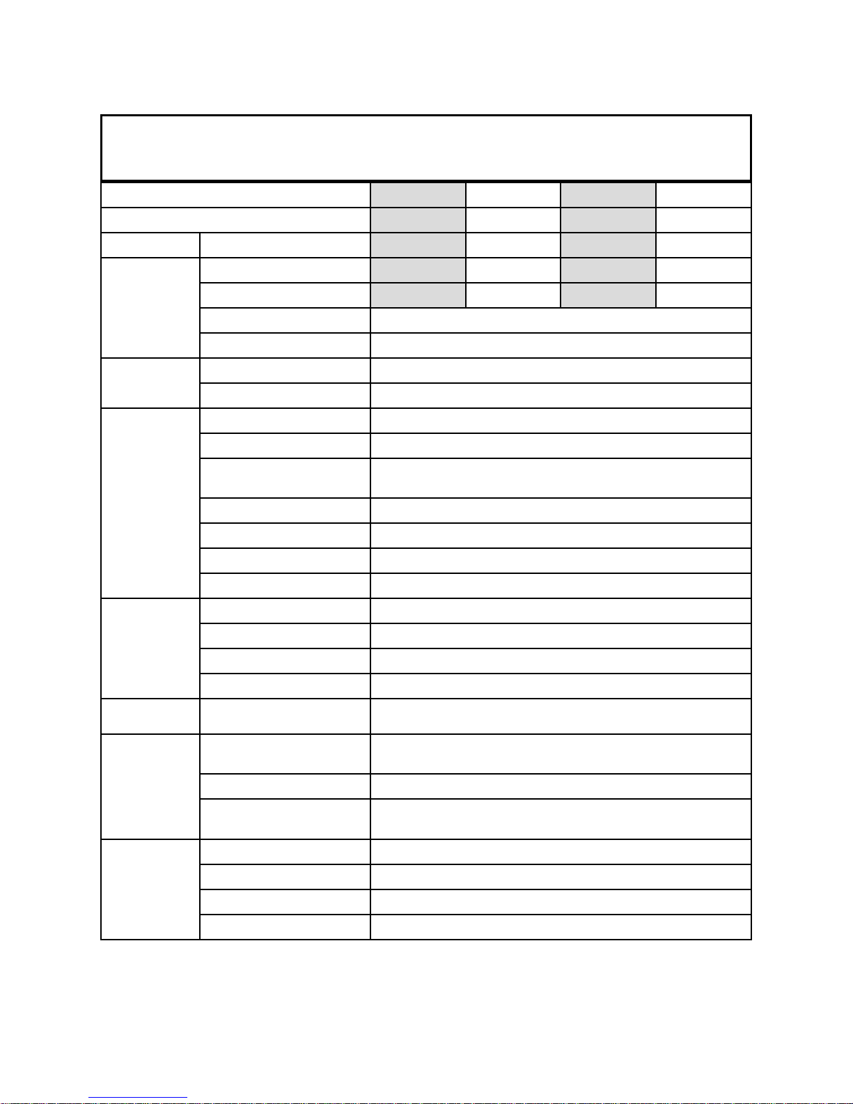
Table 1.1.1: SV100 Drive Specifications for 230 V olts
SpaceVector™ Drive Specifications
(230 V)
.oNtraPevirD 10-58464420-584644 30-58464440-584644
gnitaR .feR
gnitaRtuptuO
gnitaRtupnI
lortnoC
.oNledoMevirD
rewoP
tnerruC
ycneuqerF.xaMzH021
egatloVV032-002
egatloVesahp3-)%01±(V032-002
ycneuqerF)%5±(zH06ro05
dohteMMWProtceVecapS
noituloseRycneuqerFzH10.0
ycaruccAycneuqerF
oitaRF/VelbammargorpresUdnaraeniL
rotsiseRBDhtiweuqroTgnikarB%051
yticapaCdaolrevOetunim1rof%051
tsooBeuqroTelbammargorp%02-0
dohteMevitceleSlanimreT/dap-yeK
2.12.2 2.32.5
PH1PH2 PH3PH5
.1AVk99.2AVk .4AVk2.6AVk1
pmA5pmA5.7 pmA11pmA61
ycneuqerFmumixaMfo%10.0:gnitteslatigiD
ycneuqerFmumixaMfo%1.0:gnittesgolanA
noitarepO
elbammargorP
tupnI
noitcetorP
latnemnorivnE
snoitidnoC
ytidimuH)gnisnednoc-non(%09rednU
edutitlA)teef0823(m000,1rednU
noitceleSycneuqerFAm02~4,CDV01~0:golanA/dapyeK
emit.leceD/.leccA.ces999-1.0
noitceleSdeepSelbammargorp,spets3otpU
tupnIelbammargorPP,3,2-stupnieerhT
noitacidnItluaF
noitneverPllatSnoitneverptnerrucrevO
eruliaFrewoPsuoenatnatsnI
erutarepmeTtneibmA)F°401ot°41(C°04ot°01-
metsySgnilooCriAdecroF
rotoM,taehrevoretrevnI,tnerrucrevO,egatlovrednU,egatlovrevO,daolrevO
ssolesahP,rorreUPC,taehrevo
noitareposuounitnoc:cesm51rednU
)evitceles(tratsercitamotua:cesm51revO
7
Page 8
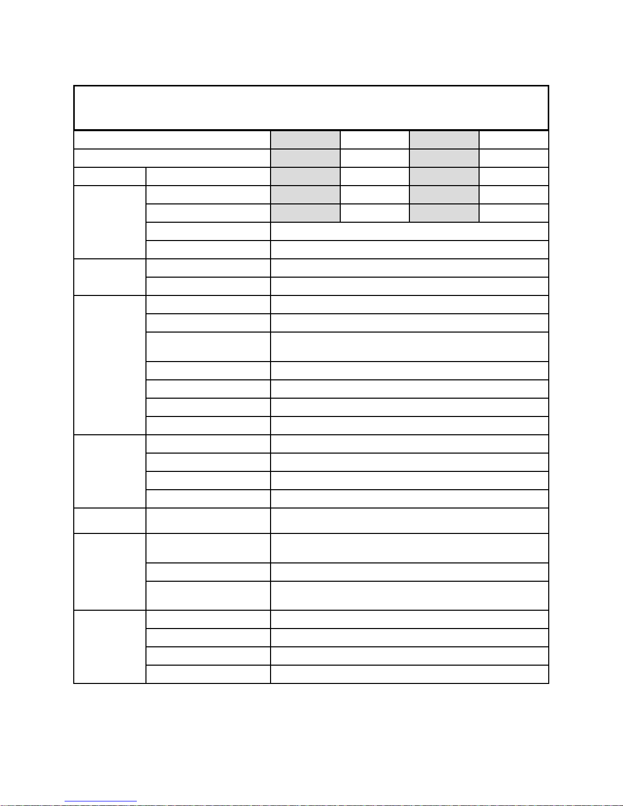
Table 1.1.2: SV100 Drive Specifications for 460 V olts
SpaceVector™ Drive Specifications
(460 V)
.oNtraPevirD 50-58464460-584644 70-58464480-584644
gnitaR .feR
gnitaRtuptuO
gnitaRtupnI
lortnoC
.oNledoMevirD
rewoP
tnerruC
ycneuqerf.xaMzH021
stlovtuptuOV064-083
egatloVesahp3-)%01±(V064-083
ycneuqerF)%5±(zH06ro05
dohteMMWProtceVecapS
noituloseRycneuqerFzH10.0
ycaruccAycneuqerF
oitaRF/VelbammargorpresUdnaraeniL
rotsiseRBDhtiweuqroTgnikarB%051
yticapaCdaolrevOetunim1rof%051
tsooBeuqroTelbammargorp%02-0
dohteMevitceleSlanimreT/dapyeK
4.14.2 4.34.5
PH1PH2 PH3PH5
AVk9.1AVk3 AVk2.4AVk1.6
pmA5.2pmA4 pmA5.5pmA8
ycneuqerFmumixaMfo%10.0:gnitteslatigiD
ycneuqerFmumixaMfo%1.0:gnittesgolanA
noitarepO
elbammargorP
tupnI
noitcetorP
latnemnorivnE
snoitidnoC
ytidimuH)gnisnednoc-non(%09rednU
edutitlA)teef0823(m000,1rednU
noitceleSycneuqerFAm02~4,CDV01~0:golanA/dapyeK
emit.leceD/.leccA.ces999-1.0
noitceleSdeepSelbammargorp,spets3otpU
tupnIelbammargorPP,3,2-stupnieerhT
noitacidnItluaF
noitneverPllatSnoitneverptnerrucrevO
eruliaFrewoPsuoenatnatsnI
erutarepmeTtneibmA)F°401ot°41(C°04ot°01-
metsySgnilooCriAdecroF
rotoM,taehrevoretrevnI,tnerrucrevO,egatlovrednU,egatlovrevO,daolrevO
ssolesahP,rorreUPC,taehrevo
noitareposuounitnoc:cesm51rednU
)evitceles(tratsercitamotua:cesm51revO
8
Page 9
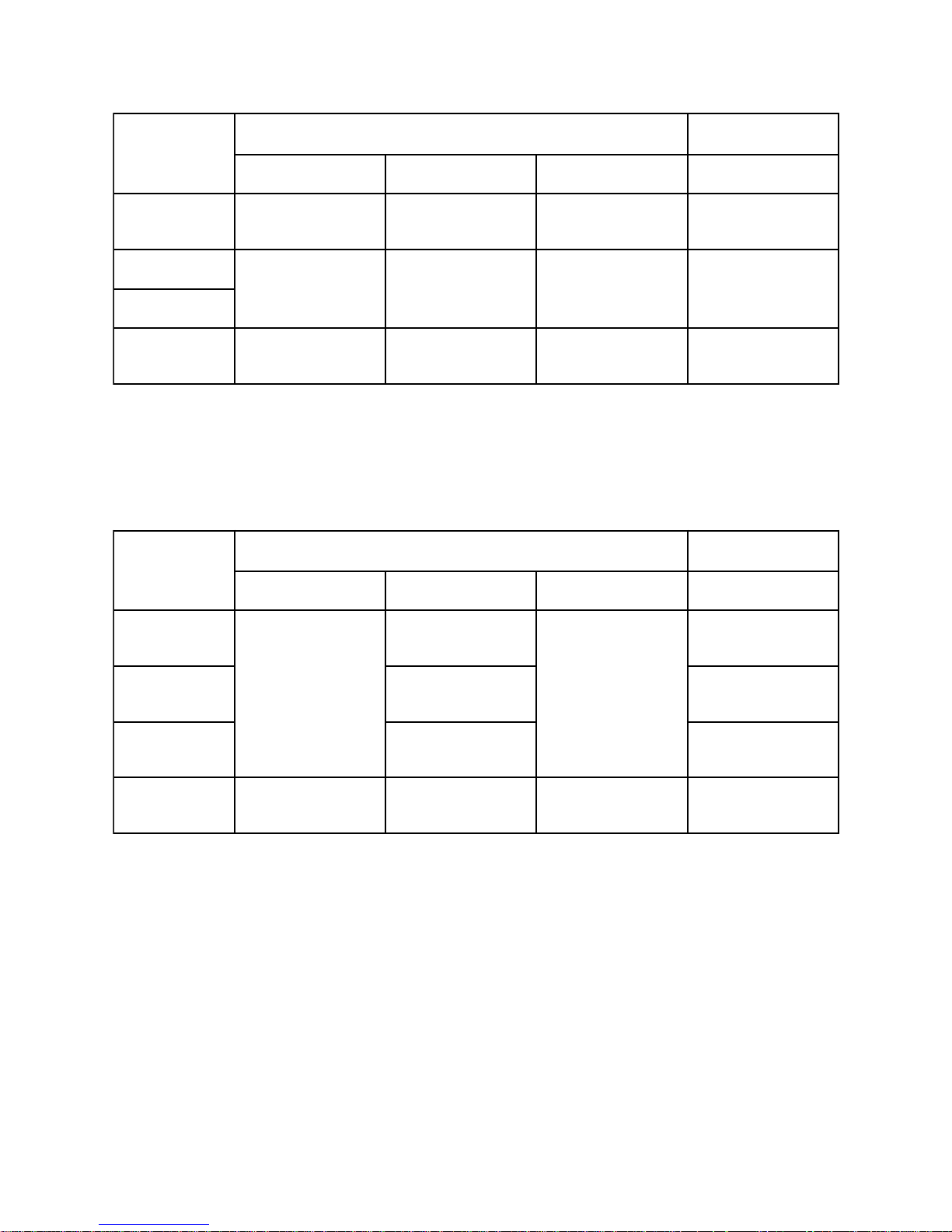
Table 1.1.3: 230 V Class Dynamic Braking Resistors
.P.HecivreSDroC,B,AssalCecivreSEssalC
*BLMhtiwtsioH*BLMtuohtiwtsioHesrevarT*BLMtuohtiwtsioH
11A-584644
2
3
54A-584644
001 W
2A-584644
05 W
33 W
1A-584644
001 W
8A-584644
06 W
3B-584644
03 W
*MLB = Mechanical Load Brake
Table 1.1.4: 460 V Class Dynamic Braking Resistors
.P.H
*BLMhtiwtsioH*BLMtuohtiwtsioHesrevarT*BLMtuohtiwtsioH
1
0A-584644
002 W
1A-584644
001 W
2A-584644
05 W
4A-584644
33 W
ecivreSDroC,B,AssalCecivreSEssalC
1A-584644
001 W
8A-584644
06 W
3B-584644
03 W
0A-584644
002 W
2
3
5
0A-584644
002 W
1A-584644
001 W
*MLB = Mechanical Load Brake
002 W
002 W
021 W
002 W
031 W
0A-584644
3A-584644
5A-584644
002 W
0B-584644
002 W
2B-584644
021 W
5A-584644
0B-584644
2B-584644
9
Page 10

Section 1.2: Mounting the Drive
1.2.1 Environmental Conditions
1. V erify the ambient condition of the drive mounting location. The ambient
temperature range should be 14° to 104°F (-10° to 40°C) for NEMA 1 and or NEMA
4/12 enclosures.
2. The relative humidity should be less than 90% (non-condensing), below the altitude
of 3280 ft or 1000 m.
3. Do not mount the drive in direct sunlight. The drive should also be isolated from
excessive vibration.
4. The drive should be protected from moisture, dust, metallic particles, corrosive
gases and liquids.
5. Consult Factory for severe environments.
1.2.2 Electrical Conditions
1. V erify that Input voltage is within drive nameplate +/- 10%. If input line voltage
varies due to sags and / or surges input line reactors are recommended.
2. Analog input requires individually shielded twisted pair cable for installations where
the cable leaves the control cabinet.
3. If length of motor leads between drive and motor exceed 100 ft. (30 m) a load reactor between drive and motor is recommended.
1.2.3 Mounting
The SV100 must be mounted vertically with sufficient space (horizontally and vertically)
between adjacent equipment. See Figure 1.2.1. See Figures 1.2.2 – 1.2.4 for actual
drive dimensions.
10
Page 11
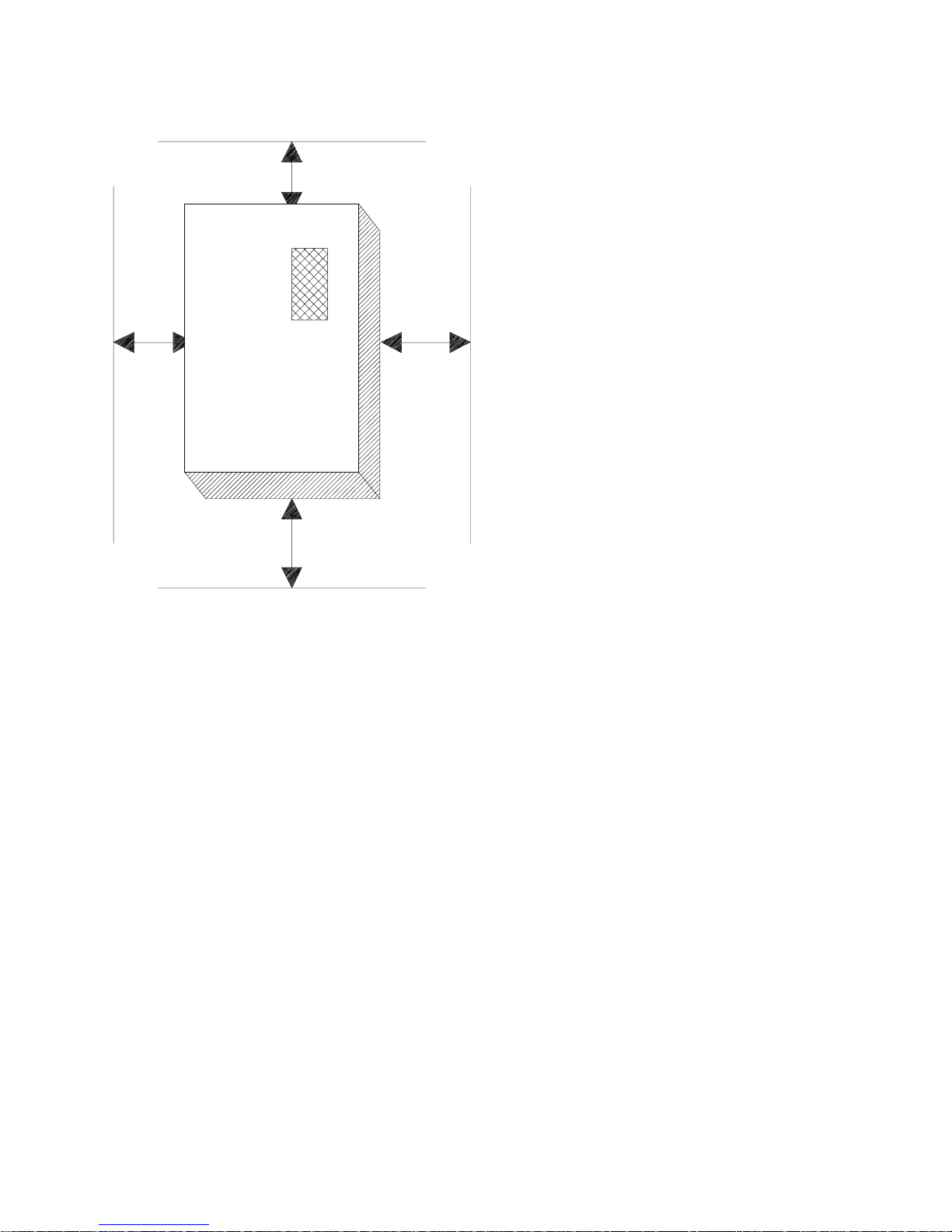
Fig. 1.2.1: Recommended Clearances for Drive Mounting
A
B
B
A: over 6.0’’ (15cm)
B: over 2.0’’ (5cm)
A
Note: Allow more room between drive and other heat producing components (such as
transformers and drive ballast resistors) than shown in Fig. 1.2.1. These
components radiate enough heat to damage the drive and its internal
components.
11
Page 12
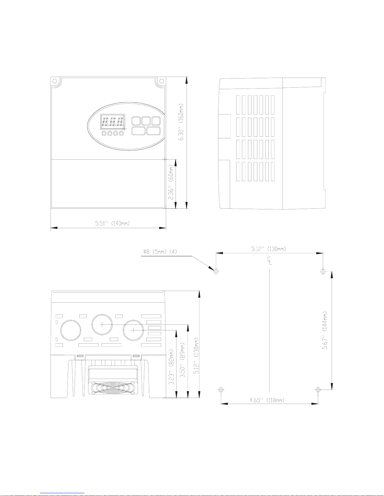
Drive Dimensions and Weights
Fig. 1.2.2: SV100 Part Nos. 446485-01 / 446485-02 4.6lbs/5.1lbs
(2.1kg/2.3kg)
12
Page 13
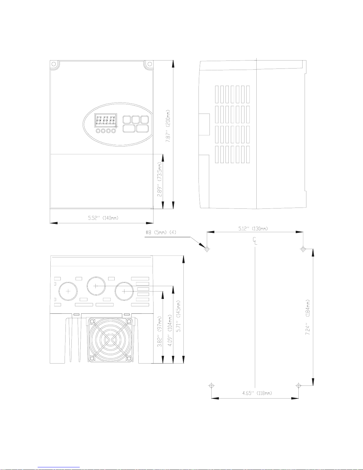
Fig. 1.2.3: SV100 Part Nos. 446485-03 / 446485-04 7.1lbs / 7.7lbs
446485-05 / 446485-06 (3.2kg/3.5kg)
13
Page 14
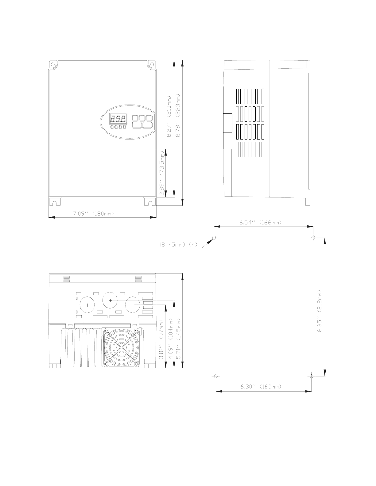
Fig. 1.2.4: SV100 Part Nos. 446485-07 / 446485-08 7.7lbs(3.5kg)
14
Page 15
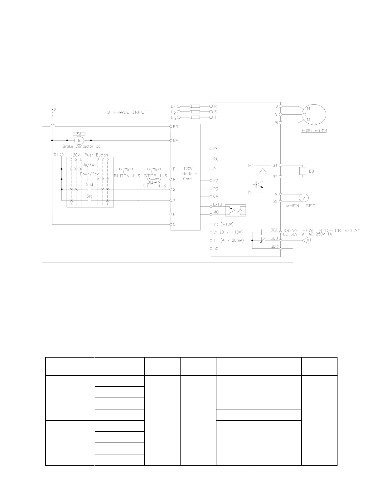
Section 1.3: Wiring the Drive
1.3.1 Remove Cover From Drive
Figure 1.3.1 below is a reference for the basic Input / Output Terminals of a 460 VAC
SV100 drive. 230 VAC Models are wired the same.
Fig. 1.3.1: SV100 Layout For Basic Wiring
Drawings representative of other configurations are located in the Appendix.
1.3.2 Check For Correct Wire Gauges
Insure the correct wire gauges for the input and output power leads are being used before
wiring the drive. Use Table 1.3.1 for reference.
Table 1.3.1: Wire Gauge Reference Table.
SV100
Drive Class
230V Class
460V Class
Drive Rated
Amp.
5.0
7.5
11
16 10 10
2.5
4
5.5
8
Input
AWG
12 12
Output
AWG
Ground
AWG
12 12
12 12
DB Resistor
AWG
Control
AWG
16
15
Page 16
1.3.3 Fuse and Circuit Breaker Selection
Reference Table 1.3.2 to properly apply fuses and circuit breakers to the drive.
Table 1.3.2: Fuse and Circuit Breaker Selection
SV100 Drive
Voltage
230V
460V
Ref.
HP
1 446485-01 10 A 15 A
2 446485-02 10 A 15 A
3 446485-03 20 A 25 A
5 446485-04 25 A 30 A
1 446485-05 5 A 5 A
2 446485-06 8 A 10 A
3 446485-07 10 A 15 A
5 446485-08 15 A 20 A
SV100
Part Number
Fuse Rating
Class (J)
Molded Case
Circuit Breaker
1.3.4 Power Lead Wiring
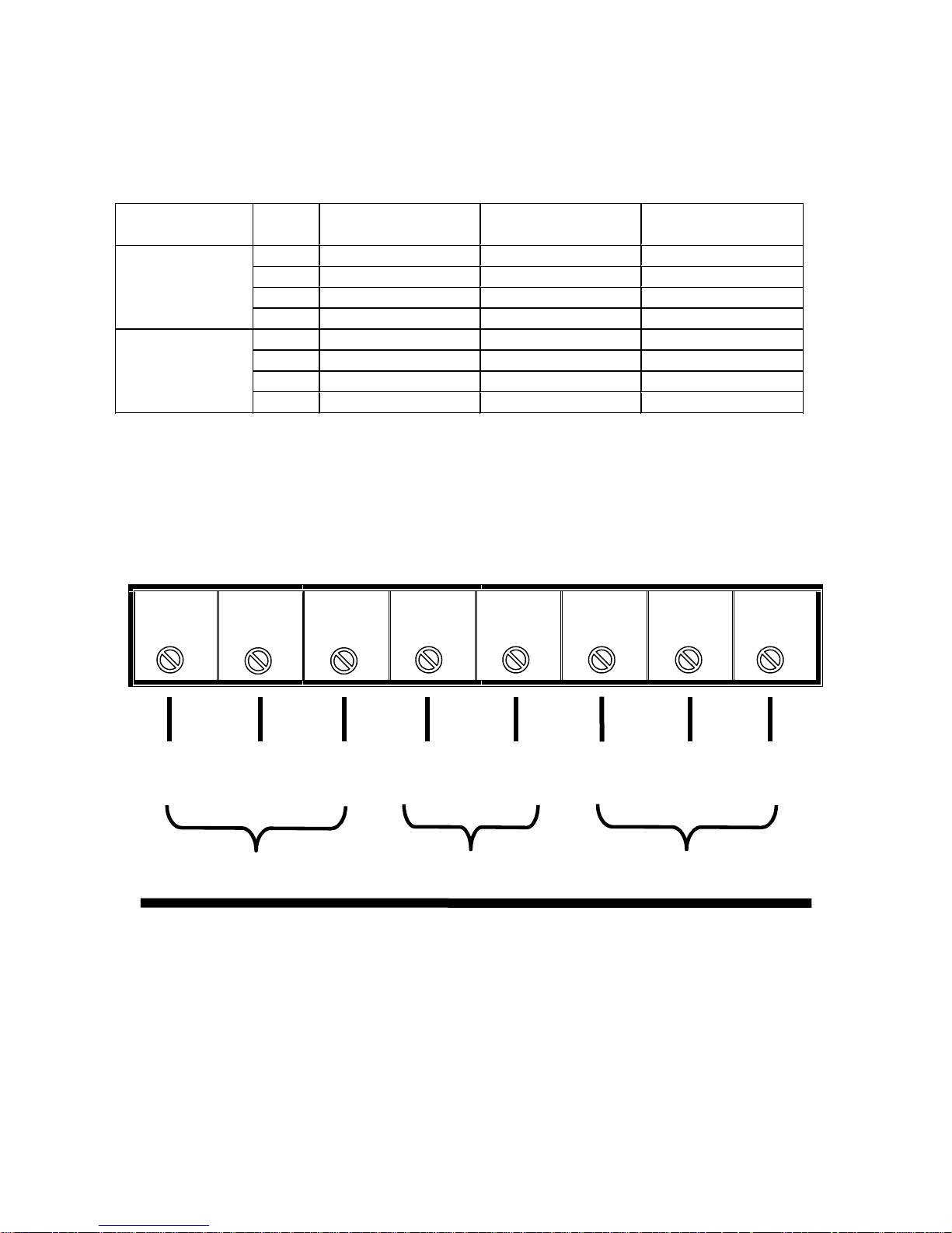
Use Figure 1.3.2 as shown below to assist in wiring the power leads to the drive.
Fig. 1.3.2: Input / Output Power and Dynamic Braking Resistor Wiring Diagram.
Arrangement of Power Terminal Strip
RSTB1B2UVW
L1 L2 L3 B1 B2 T1 T2 T3
3 Phase Input Power Dynamic Braking 3 Phase Output to Motor
230 VAC or 460 VAC Resistor Unit
Note 1:
Note 2:
16
Slotted Tongue Terminals are recommended for connections shown in
Figure 1.3.2.
Use drive chassis to ground the drive to the panel.
Page 17
1.3.5 Wire the Dynamic Braking Resistor
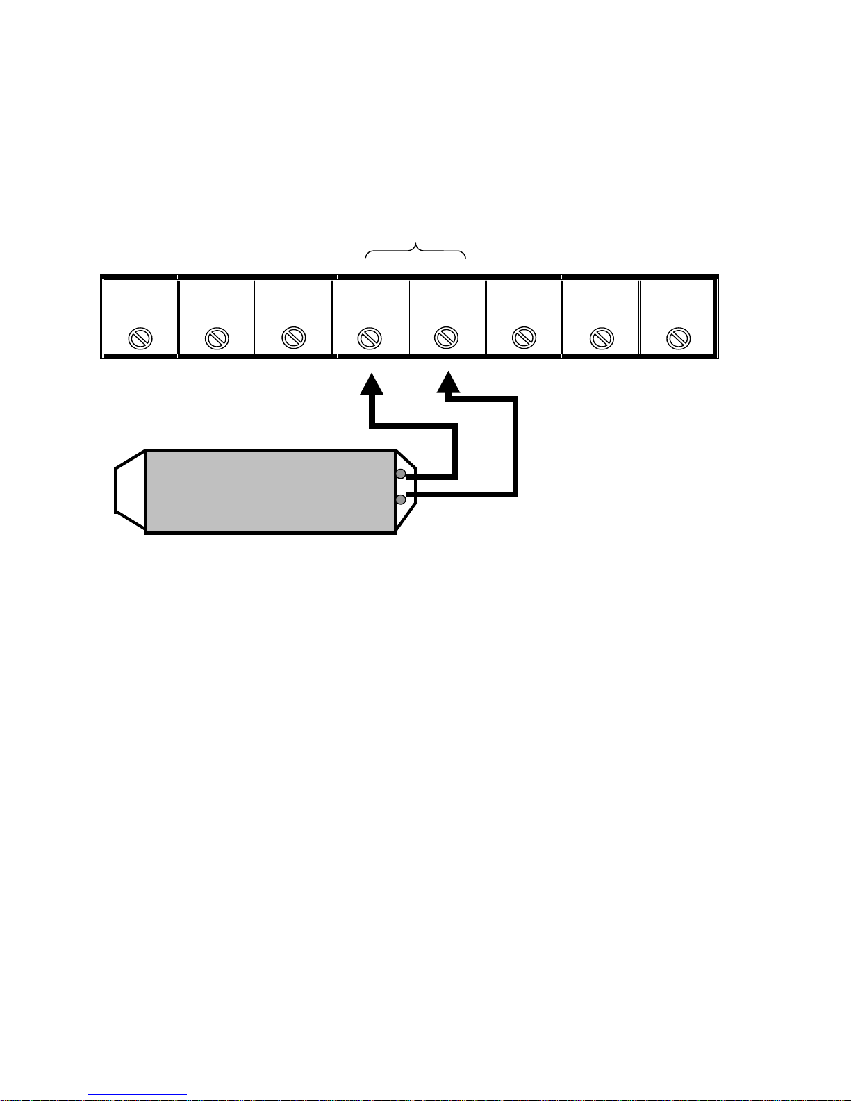
Use Figure 1.3.3 as shown below to assist in wiring the dynamic braking
resistor to the power terminal strip.
Fig. 1.3.3: Power Terminal Strip Connection for the Dynamic Braking Resistor
DB R es ist or
Term in als
R
S
T
B1
B2
U
V
W
CAUTION! OBSERVE CAUTION AS RESISTOR MAY BE HOT!
•
• If the dynamic braking resistor has a bad connection or is missing, the drive
• The dynamic braking resistor generates a lot of heat during its operation.
Dynamic Braking Resistor
The Dynamic Braking Resistors
form of heat. They are required for all hoist and traverse applications.
DC Bus voltage may increase, resulting in an overvoltage fault.
Place the resistor where it m ay dissipate this energy without dam aging other
components.
dissipate the motor rotational energy in the
17
Page 18
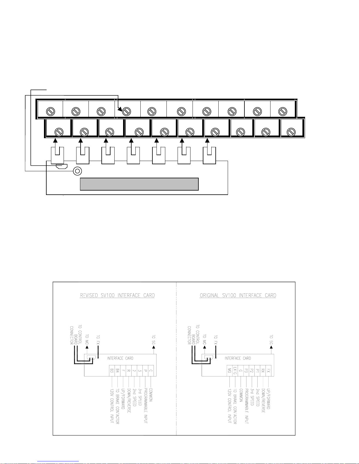
1.3.6 Interface Card Connection
The SV100 SpaceVector Drive comes equipped with the 120 VAC Interface Card
TM
installed. Fig. 1.3.4 below shows the connection of the interface card to the control
terminal strip.
Fig. 1.3.4: Interface Card Connection to the Control Terminal Strip
To jumper on circuit board
30A 30C
30B FX BX RST CM VR V1 5G
Control Terminal Strip
MO EXTG RX CM P1 P2 P3 I FM 5G
FX
Input Terminals for Pushbutton
Input Terminals for Pushbutton
Input Terminals For Pushbutton
1.3.7 Connect the Pushbutton Pendant Control Wires
Wire the pushbutton pendant control to the pendant input terminals. See Fig. 1.3.5
below for wiring diagram. Once the pendant is wired, check to determine that the motor
turns in the correct direction with respect to the pendant button pressed. Consult
Chapter 4 Troubleshooting for help if there is a problem.
Note: The Interface Card requires 120 VAC input signal from your external pushbutton.
Fig. 1.3.5: Pushbutton Wiring Diagrams for the Original and Revised Versions
120V AC Input from Pushbutton 120V AC Input from Pushbutton
18
Page 19
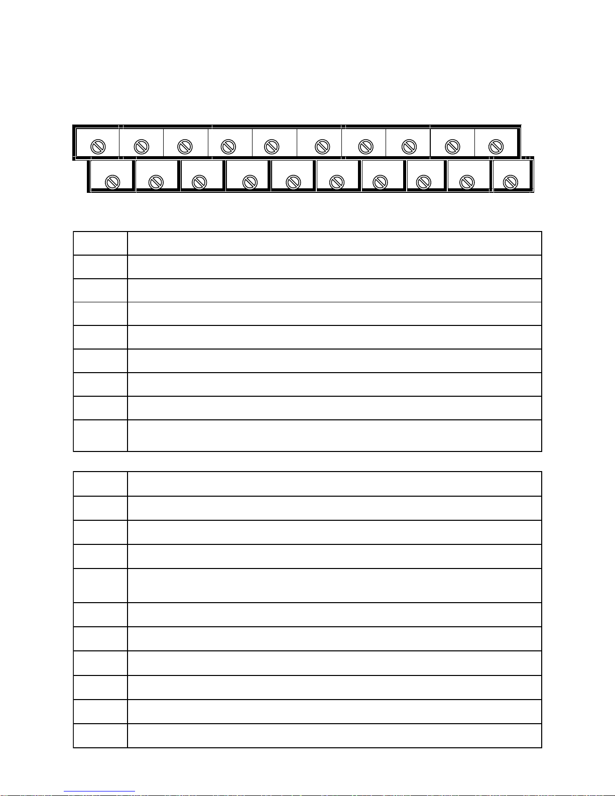
1.3.8 Control Wire Description
Reference the control wiring terminal in Figure 1.3.6 below and the descriptions of each
terminal listed in Tables 1.3.4 and 1.3.5.
Fig. 1.3.6: Control Wiring Terminal
30A 30C
30B FX BX RST CM VR V1 5G
MO EXTG RX CM P1 P2 P3 I FM 5G
Table 1.3.4: Most common drive control terminals used.
lobmySnoitcnuF
XF
XR
OM
GTXE
1P
2P
3P
]lanimreTtupnIdraCecafretnICAV021no2[2deepS
]lanimreTtupnIdraCecafretnICAV021no3[3deepS
]lanimreTtupnIdraCecafretnICAV021noF[1deepSlanimretdnammocnoitceriddrawroF/pU
]lanimreTtupnIdraCecafretnICAV021noR[1deepSlanimretdnammocnoitceridesreveR/nwoD
]lanimreTtupnIdraCecafretnICAV021no3B[esaelerekarbroflanimrettuptuonoitcnufitluM
]lanimreTtupnIdraCecafretnICAV021no4B[]OM[roflanimretnommoC
]lanimreTtupnIdraCecafretnICAV021noP[tupnIelbammargorP
MC
Table 1.3.5: Drive control terminals used for special applications.
lobmySnoitcnuF
1V
RV
I
MF
G5
XB
TSR
A03
B03
].xaMAm05
lanimretdnammocpotsycnegremE
lanimretdnammoctesertluaF
)Am02~4(lanimrettupniecnereferdeepstnerruC
]A1,V052CA,V03CD[)tcatnocnepolamroN(lanimrettuptuoyaleR
]A1,V052CA,V03CD[)tcatnocesolclamroN(lanimrettuptuoyaleR
]lanimreTtupnIdraCecafretnICAV021[]TSR[,]3P[,]2P[,]1P[,]XB[,]XR[,]XF[roflanimretnommoC
)lanimretnoitcennocretemoitnetoP()CDV01+~0(lanimreTtupnIecnerefeRdeepSgolanA
)lanimretnoitcennocretemoitnetoP()CDV11+(lanimret1VrofylppusrewopegatloV
.xaMCDV42+[.gnirotinoMycneuqerF,egatloV,tnerruClanretxEroflanimreTtuptuOreteM-itluM
]lanimretnoitcennocretemoitnetoP[,]MF[,]I[,]1V[roflanimretnommoC
C03
]A1,V052CA,V03CD[)lanimretnommoC(lanimrettuptuoyaleR
19
Page 20
1.3.9 Make Precautionary Checks Before Operation
1. Make sure the input voltage level to the drive is correct. Refer to the Drive Specification Tables 1.1.1 and 1.1.2.
2. Check the power and control connections. All wires should be connected tightly
to the terminal.
3. Check the 120VAC source for the control push button.
4. The length of the output wires between the SV100 and the motor must not
exceed 100 feet.
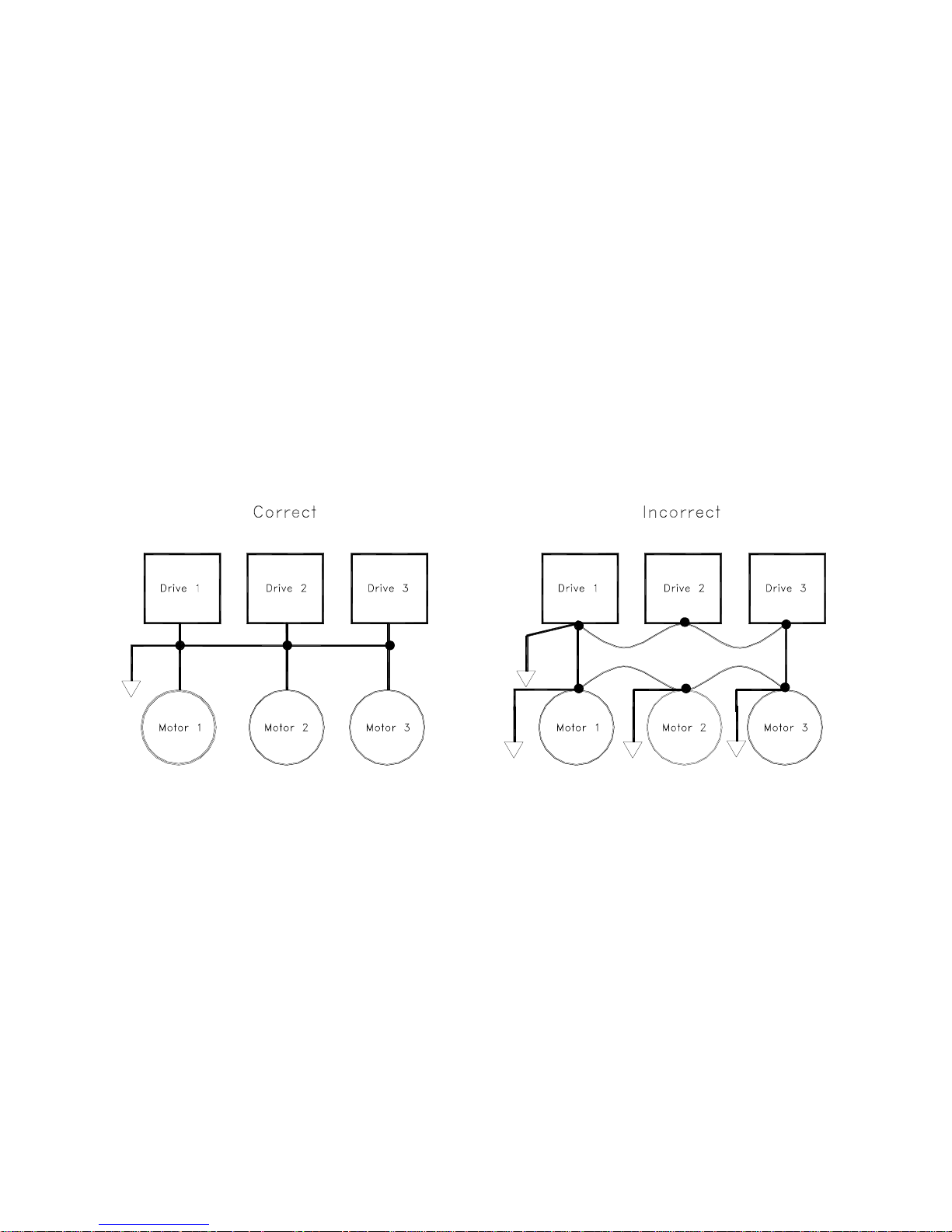
5. Check the drive and motor ground and make sure there is no ground loop
problem. Ensure that all motors and drives connected from a common panel are
connected to a single ground point. See Fig. 1.3.7 for an example.
Fig. 1.3.7 Ground Connection Comparison
20
Page 21

Chapter 2: Start Up Programming
Section 2.1: Keypad Layout
Section 2.2: Keypad Operation
2.2.1: Definitions
2.2.2: Moving Through the Program
2.2.3: Changing Control from Pendant to Keypad
Section 2.3: Initial Setup Programming
2.3.1: Programming for a Specific Application
2.3.2: Programming the Speed Selection
2.3.3: Drive Operation Checks
21
Page 22
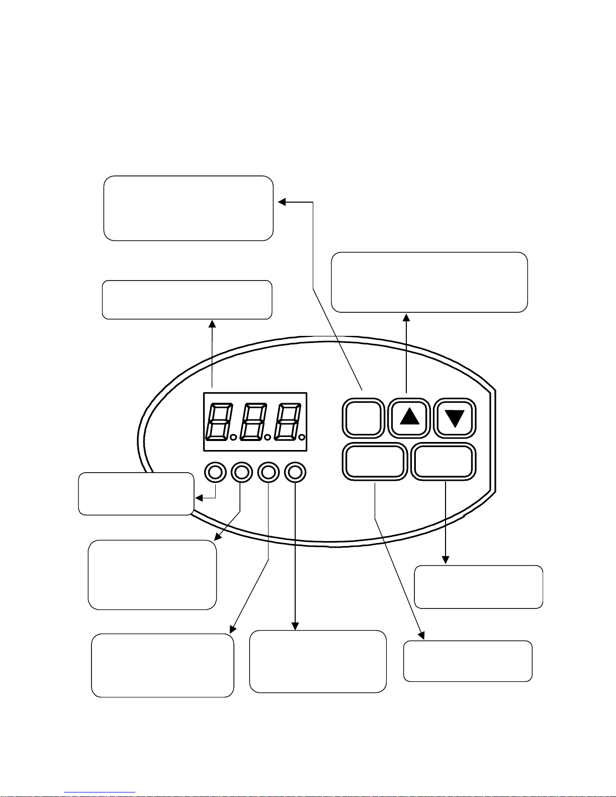
Section 2.1: Keypad Layout
The SV100 keypad consists of an LED display, status lights, and keys for easy
programming. Fig. 2.1.1 below illustrates the layout of the SV100 keypad.
Figure 2.1.1 – SV100 keyp ad layo ut
FUNC Key
• (Press Once) Starts Prog ra m ming
mode
(Press 2
•
Progra mming mode
• Displays frequenc y, c urrent, gro u p
functions and function data
nd
Time) Completes
Display
UP/DOWN Arrow Keys
Used to scroll up or do wn thr o ugh fu n ction
•
parameters
• Increase or decrease the data in
prog r a mming mod e
Run LED
ON during motor
•
operation
FWD LED
Blinks during Up / Forwa rd
•
while in Accel / Decel
• ON during Up / Forward at
selected speed
REV LED
Blinks during Down / Reverse
•
while in Accel / Decel
• ON during Down / Reverse at
selected speed
FUNC
RUN
SET LE D
• ON when in Program mo de
• OFF when not in Progr am
mode
STOP/RST
STOP/RST
Reset button for fault
•
condition
RUN Key
• Does not have any control
of drive operation
22
Page 23

Section 2.2: Keypad Operation
Keypad operation and moving through the parameters of each access level is a
straightforward process. First read the definitions below.
2.2.1 Definitions
Levels – The SV100 program consists of three levels. The levels are the User, Service,
and Advanced. Each level consists of different function commands which control how
the drive operates, senses, and performs.
User Level – This level allows programming speed, passwords, and the motion application desired. You can also monitor motor current draw and system faults in this level.
You are automatically in the User level upon power up of your drive.
Service Level (FU1 on SV100 Display) – The functions within this group primarily set
how the drive will perform, sense problems, and set parameters catered to your motor
for peak operation.
Advanced Level (FU2 on SV100 Display) – Functions within this level are reserved for
special performance characteristics and consists of advanced performance parameters.
2.2.2 Moving Through The Program
When the drive is first powered up, the first Function Code of the User Level is
displayed. Please follow the keypad button prompts illustrated in Fig. 2.2.1:
Programming Flowchart and use Table 2.2.1: Function Code List for all levels to help
follow program flow.
23
Page 24

g
Fig. 2.2.1: Programmin g Flowchart
r
Turn Power To The
SV100 On
Press the
Up Key
• You are now in the
User Level
• [Function No. 1]
Speed 1 Frequency Is
Displayed
•
[Function No. 2 - Mac]
is displayed
Press
Up Key
Press
Up Key
•
[Function No. 1] F1
is the first function in
Service Level
the
• [Function No. 2]
Acceleration time
Keep Pressin
The Up Key Until
[FU1] Is Dis p layed
Choose
Press the
Up Key
•
Notice how you go through
User Level
the
the order shown In Table
2.2.1
•
[Function No. 16] is displayed.
FU1 is where you enter into and
view all of the
functions.
Press th e
Key
• This takes you to
Service Level
the
functions in
Service Level
FUNC
Press the
Key
FUNC
Pressing either or
keys w ill allo w yo u to g et to
each function of the
respective level you are in.
To get back to the
Level
, go to [Function No.
Service Level
26] in
[Function No. 53] in the
Advanced Level
the key.
FUNC
• [Function No. 3]
Deceleration time
User
, or
and press
•
[Function No. 17] is
displaye d. F U 2 is
where you can enter
into and view al l the
Advanced Level
functions.
Pressing either the o
key will allow you
to view all functions within
User Level
the
24
• This takes you to
the Advanced
Level
•
[Function No. 1 – Command
Frequency Selection] - You
Are Now In The First Function
Advanced Level
Of The
Page 25
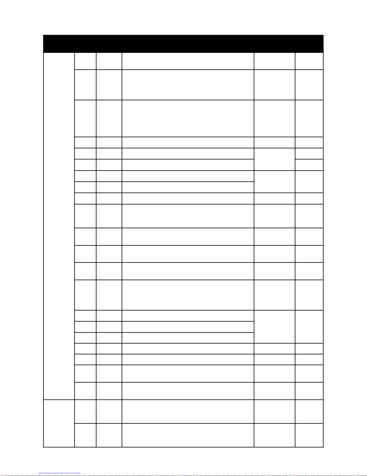
Table 2.2.1: Function Code List For All Levels
.cnuF
leveL
.oN
1
yalpsiD noitpircseD egnaR tluafeD
01
edompotsninehwdeyalpsidycneuqerf1deepS
edomnurgniruddeyalpsidtuptuoycneuqerflautcA
zH9F-0zH0.01
caM
2
(Mac)
3
4
5
6
7
8
9
01
resU
11
s8s
ruc
2ps
3ps
cca
ce8
psl
18f
(Ft1)
28f
(Ft2)
enifeDnoitoM
esrevarT:0
ekarBdaoLhtiwtsioH:1
ekarBdaoLtuohtiwtsioH:2
noitceleSdeepS
deepS2:0
elbairaVyletinifnIpetS2:1
deepS3:2
elbairaVyletinifnIpetS3:3
tnerruCSMRtuptuOsyalpsiD
2deepS
3deepS .zH00.0
emiTnoitareleccA
emiTnoitareleceD
nepOsitcatnoCCNhctiwStimiLnehwdeepSwoL1.ncFresU-0zH0.5
yalpsiDtluaF
]01.oNresU[ottluaFsuoiverPsyalpsiD
2-01
3-01
.zH9F-0
.ces999-0.ces0.3
,tLO,vO,CO
,FHP,HtE,HO
UPC,Xb,vL
.zH00.06
21
31
41
51
61
71
81
91
02
12
1
ecivreS
2
38f
(Ft3)
p8i
lca
sap
1ap
2ap
1uf
2uf
goj
(JOG)
reu
(VER)
1f
2f
]11.oNresU[ottluaFsuoiverPsyalpsiD
lanimreTtupnIfosutatSsyalpsiD
2dna3,P,4B,F,R
leveLsseccAdettimrePsyalpsiD
levelresU:rSU
leveLecivreS:rES
leveLdecnavdA:vdA
drowssaPretnE
drowssaPleveLecivreSegnahC
drowssaPleveLdecnavdAegnahC
sedoCnoitcnuFleveLecivreS
sedoCnoitcnuFleveLdecnavdA
ottessi)dnammoCpotS/nuR(1FnehwylnodeyalpsidsigoJ
)dapyeK("0"
noisreVerawtfoS
edoMPOTS/NUR
dapyeK:0
lanimreT:1
nrettaPnoitareleccA
raeniL:0
evruCS:1
999-00
nD,pU,petS
C2H
1ro01
1ro01
25
Page 26

Table 2.2.1: Function Code List For All Levels (cont.)
.cnuF
leveL
ecivreS
.oN
3
4
5
6
7
8
9
01
11
21
31
yalpsiD noitpircseD egnaR tluafeD
nrettaPnoitareleceD
3F
4F
5F
6F
7F
8F
9F
01F
11F
21F
31F
raeniL:0
evruCS:1
]2[,tupnInoitcnuF-itluMenifeD
.yllacitamotua
2deepS:0
3deepS:1
devreseR:2
)PU(gnisaercnIycneuqerF:3
dloHycneuqeF:4
]3[,tupnInoitcnuF-itluMenifeD
.yllacitamotua
2deepS:0
3deepS:1
devreseR:2
)PU(gnisaercnIycneuqerF:3
dloHycneuqeF:4
]P[,tupnInoitcnuF-itluMenifeD
.yllacitamotua
2deepS:0
3deepS:1
devreseR:2
)PU(gnisaercnIycneuqerF:3
dloHycneuqeF:4
tuptuOnoitcnuF-itluM
)72H,62H(langiSnoitarepOllatS:2
)92H,82H(langiSdaolrevO:3
langiS)tluafVL(egatlov-rednU:4
langiSpotS/nuR:5
noitarepOfoycneuqerFmumixaM.zH021-0.04.zH0.06
ycneuqerFffotuCevirD.zH0.5-10.0.zH5.0
ycneuqerFllewDgnitratS.zH9F-0.0.zH0.3
emiTllewDgnitratS
.ces5.0=tsioH:seulaVlaitinI
.ces1.0=esrevarT
1ro00
stupniesehtstespetSdeepSrofputeSorcaM:ETON
7-03
tupnI)SL(hctiwStimiLpotSetaidemmI:5
noitomtsiohrofdednemmocertoN-SLpotSotpmaR:6
)9.oNnoitcnuFresU(SLdeepSwoL:7
stupniesehtstespetSdeepSrofputeSorcaM:ETON
7-02
tupnI)SL(hctiwStimiLpotSetaidemmI:5
noitomtsiohrofdednemmocertoN-SLpotSotpmaR:6
)9.oNnoitcnuFresU(SLdeepSwoL:7
stupniesehtstespetSdeepSrofputeSorcaM:ETON
7-02
tupnI)SL(hctiwStimiLpotSetaidemmI:5
noitomtsiohrofdednemmocertoN-SLpotSotpmaR:6
)9.oNnoitcnuFresU(SLdeepSwoL:7
)desolCyllamroN(emitgnihcaerycneuqerF:0
)nepOyllamroN(emitgnihcaerycneuqerF:1
5-01
esrohecnereferfI.yrotcaftateserpnoitcelesledomevirD
ehtrof5.2.5noitceSees,yrassecensiegnahcgnittesrewop
srebmuntrapevirddnasledomevirdneewtebecnereferssorc
)ycneuqerFesaB(rotoMfoycneuqerFdetaR.zH9F-0.04.zH0.06
evirD
.oNledoM
.ces0.01-1.0.ces5.0
41
41F
26
noitceleSnrettaPF/V
raeniL:0
-devreseR:1 .esutonoD
F/VresU:2
2ro00
Page 27
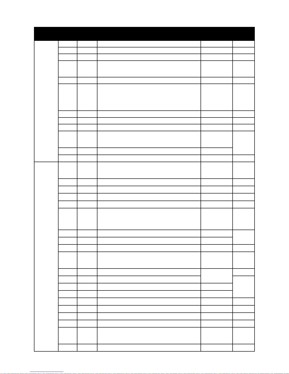
Table 2.2.1 - Function Code List For All Levels (cont.)
.cnuF
leveL
.oN
51
61
71
81
91
02
ecivreS
12
22
32
42
52
62
1
2
3
4
5
6
7
8
decnavdA
:gninraW
silevelsihT
deniarTrof
rotceVecapS
ecivreS
9
dednemmoceR
01
.ylnolennosrep
11
21
41
51
61
71
81
91
02
yalpsiD noitpircseD egnaR tluafeD
51F
61F
71F
81F
91F
tnemtsujdAegatloVtuptuO%011-05%001
)ycneuqerFTDF(gnitteS
gnitteSdnaBlangiSgnihcaeRycneuqerF.zH0.03-0.0.zH0.0
edoMpotS
02F
gnikarBnoitcejnICD:1
potSetaidemmI:2
ekarBnoyaleD:3
12F
emiTyaleDekarB.ces0.52-0.0.ces0.0
22F
32F
42F
evitcanI:0
evitcA:1
52F
ef
sretemaraPgnignahCkcoL99U-0U
puorGresUotnruteR
dohteMnoitceleSycneuqerFdnammoC
1H
dapyeK:0
golanA:1
2H
3H
4H
5H
edoMtupnIgolanA
6H
(tupnIegatloV:0)V01~0
tupnItnerruC:1)Am02~4(
tupnItnerruC+egatloV:2
7H
8H
9H
niaGretliFtupnIgolanA%002-1
niaGtupnIgolanA%001-05
saiBtupnIgolanA%001-0%5
noitceriDtupnIgolanA
01H
tceriD:0
esrevnI:1
11H
21H
31H
ssapyBotycneuqerF.zH9F-0.0
41H
51H
61H
egatloVgnikarBCD%0.02-0%5
71H
81H
emiTgnikarBCD.ces0.02-0.0.ces0.2
ycneuqerFgnitarepOmumixaM
ycneuqerFgnitarepOmuminiM
ssapyBotdnaBycneuqerF.zH0.03-0.0
ycneuqerFgnikarBCD.zH0.02-0.0.zH0.5
emiTkcolBgnikarBCD.ces0.5-0.0.ces5.0
noitasnepmoCpilS
91H
evitcanI:0
evitcA:1
02H
)3.3noitceSeeS(pilSrotoMdetaR.zH0.5-0.0.zH0.3
nuRdrawroF/pUgnirudtsooBeuqroTteS%02-0%5
nuResreveR/nwoDgnirudtsooBeuqroTteS%02-0%2
langiSgnihcaeRycneuqerF-ycneuqerFesaeleRekarB
.zH9F-10.0.zH10.3
)tluafeD(.zH10.0+.qerFllewDgnitratS=.qerFTDF
noitomtsiohrofdednemmocertoN-potSotpmaR:0
3-02
dapyeKotyromeMniaMmorfdaeRretemaraP1ro00
yromeMniaMotdapyeKmorfetirWretemaraP1ro00
gnitteSyrotcaFtluafeDotsretemaraPteS
1ro0
0
1ro00
)41FnoitcnuFecivreSeeS(1ycneuqerFF/VresU.zH9F-0.0.zH0.5
)41FnoitcnuFecivreSeeS(1egatloVF/VresU%001-0%61
)41FnoitcnuFecivreSeeS(2ycneuqerFF/VresU.zH9F-0.0.zH0.03
)41FnoitcnuFecivreSeeS(2egatloVF/VresU%001-0%05
2-00
%001
1ro00
.zH9F-0.0
1ro00
.zH0.06
.zH0.031
27
Page 28
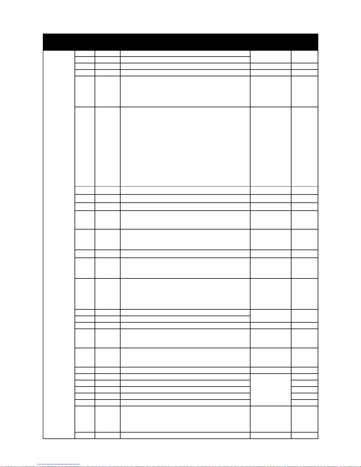
Table 2.2.1 - Function Code List For All Levels (cont.)
.cnuF
leveL
decnavdA
:gninraW
silevelsihT
dednemmoceR
deniartrof
rotceVecapS
ecivreS
.ylnolennosrep
.oN
12
22
32
42
yalpsiD noitpircseD egnaR tluafeD
12H
)3.3noitceSeeS(tnerruCrotoMdetaR
22H
32H
42H
rebmuNyrteR01-00
emiTyrteR.ces0.01-0.0.ces5.0
edoMyrteR
52
52H
tluaFVLgnirudnoitarepo-noN:1
yrteRgnirudnoitarepo-noN:2
stluaFllanignivirD:3
edoMnoitneverPllatS TSIOHNOESUTONOD
0=eulaVlaitinItsioH
1=eulaVlaitinIesrevarT
elbasiD:0
62
62H
noitareleccAgniruD:1
deepSydaetSgniruD:2
noitareleceDgniruD:4
deepSydaetSdnanoitareleceDgniruD:6
72
82
92
72H
leveLllatS%051-03%051
82H
92H
)tLO(emiTtimiLtnerruCrevO
03
03H
.ces1.0=eulaVlaitinItsioH
.ces0.03=eulaVlaitinIesrevarT
13
13H
evitcanI:0
evitcA:1
23
23H
leveLHtE%051-03%051
epyTrotoM
33
33H
lareneG:0
)gnilooCriAdecroF(laicepS:1
0=eulaVlaitinItsioH
43
43H
1=eulaVlaitinIesrevarT
evitcanI:0
evitcA:1
53
63
73
53H
63H
73H
emiTnoitareleccAhcraeSdeepS
emiTnoitareleceDhcraeSdeepS
emiTkcolBhcraeSdeepS.ces0.5-0.0.ces0.0
tratseRteseR
83
83H
evitcanI:0
evitcA:1
tratSnOrewoP
93
93H
evitcanI:0
evitcA:1
04
14
24
34
44
54
04H
14H
24H
34H
44H
54H
devreseR 0
devreseR 0
devreseR 0
devreseR 0
devreseR 0
ycneuqerFreirraC.zHk51-3.zHk3
edoMreteM-itluM
64
64H
ycneuqerF:0
egatloVtuptuO:1
tnerruCtuptuO:2
74
74H
tnemtsujdAreteM-itluM%021-0%001
)3.3noitceSeeS(tnerruCrotoMdaoLoN
A0.06-1.0
yrteRdnatluaFVLgnirudnoitarepo-noN:0
3-00
BDHTIWNOITOMESREVARTROF.NOITOM
.7HGUORHT4SEULAVESUTONODROTSISER
7-00
deepSydaetSdna.noitareleccAgniruD:3
.noitareleceDdna.noitareleccAgniruD:5
deepSydaetSdna,leceD,leccAgniruD:7
)7FnoitcnuFecivreSees(leveLdaol-revO%051-03%051
)7FnoitcnuFecivreSees(emiTdaol-revO.ces0.03-1.0.ces0.01
.ces0.06-0.0.ces1.0
)noitceteDlamrehTcinortcelErotoM(HtE
1ro00
1ro00
tratseR)eruliaFrewoPsuoenatnatsnI(FPI
1ro00
.ces0.01-1.0.ces0.2
1ro00
1ro01
2-00
elbaTeeS
2.2.5
28
Page 29
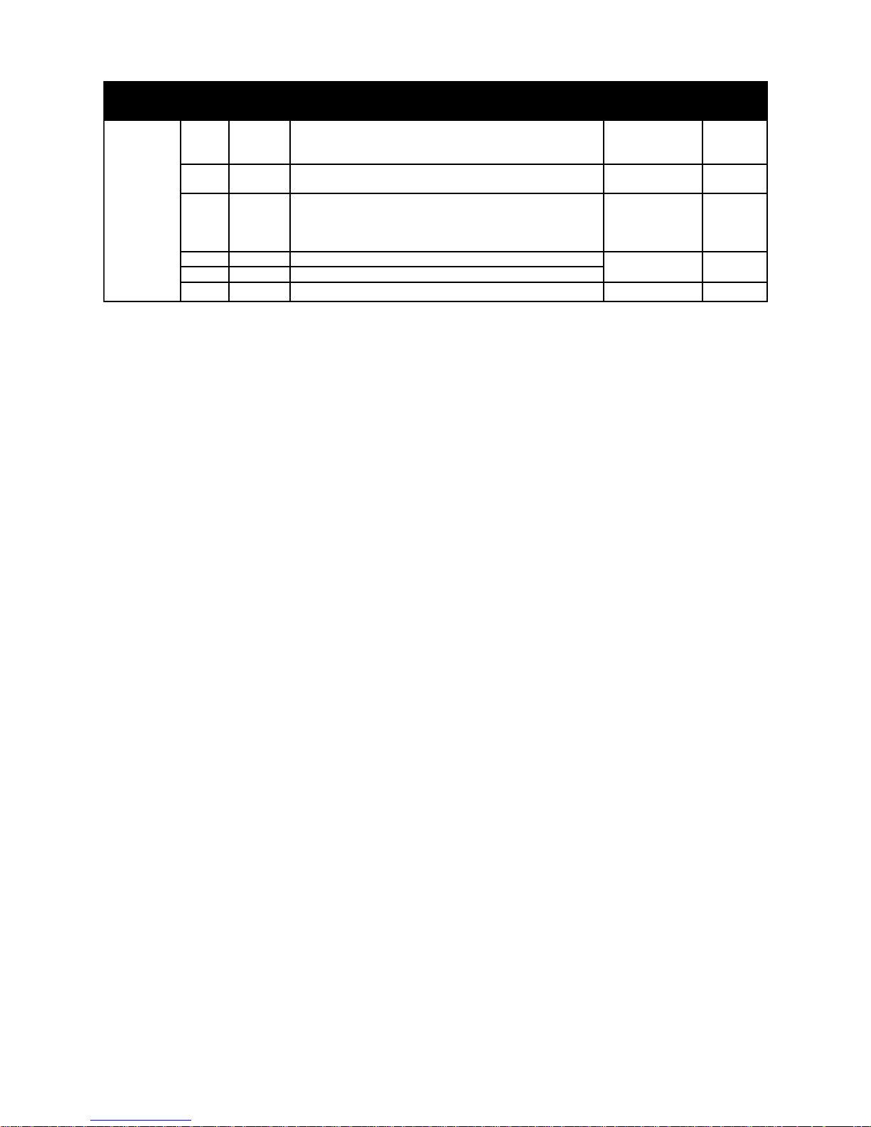
Table 2.2.1 - Function Code List For All Levels (cont.)
.cnuF
leveL
decnavdA
:gninraW
silevelsihT
dednemmoceR
deniartrof
rotceVecapS
ecivreS
.ylnolennosrep
.oN
yalpsiD noitpircseD egnaR tluafeD
)rotalugeRegatloVcitamotuA(RVA
84
84H
evitcanI:0
evitcA:1
94
94H
)kcehC
-elbanEgniggulPesreveR TSIOHNOESUTONOD
05
05H
NOITOM
evitcanI:0
evitcA:1
15
25
35
15H
25H
ef
leveLresUotnruteR
emiTnoitareleccAgniggulPesreveR
emiTnnoitareleceDgniggulPesreveR
1ro00
ssoLesahPelbasidot.cesm0(emiTkcehCssoLesahP
.cesm0005-0.cesm05
1ro00
.ces999-0.0.ces5.1
29
Page 30
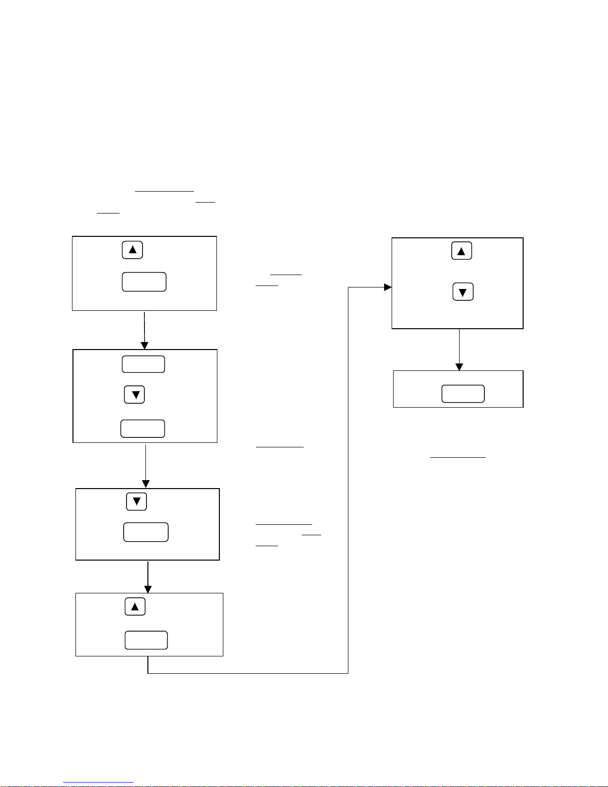
2.2.3 Changing Control from Pendant to Keypad - Jog Mode
The SV100 comes preset with pendant control. If the user wishes to change to keypad
control, refer to Figure 2.2.2 below. Use Table 2.2.1: Function Table for All Levels for
reference.
Fig. 2.2.2 – Flowchart showing how to change from pendant control to keypad control.
• Changing control mode from
pendant to keypad is done in
F1 of the
Assuming you are in the
Level
Service Level.
User
, follow the flowchart.
Press the key until is
displayed.
Press the key.
will be displayed.
Press the key.
will be displayed.
Press the key.
will be displayed.
Press the key.
Press the key until is
displayed.
Press the key.
will be displayed.
FUNC
FUNC
FUNC
FUNC
• You have
now entered
Service
the
Level
You have now
•
changed the
control from
pendant to
keypad.
function will
now be an
option in the
User Level.
• You have now
moved from the
Service Level
back to the
Level
JOG
User
Pressing the key will
rotate the motor in the
Up / Forward direction.
Pressing the key will
rotate the motor in the
Down / Reverse direction.
To exit keypad control mode,
press the key.
• To switch back to Pendant
control, go back to F1 in
the Service Level and
change the 0 to a 1.
FUNC
Press the key until
displayed.
Press the key.
30
FUNC
is
• You are now in
keypad control
mode
Page 31
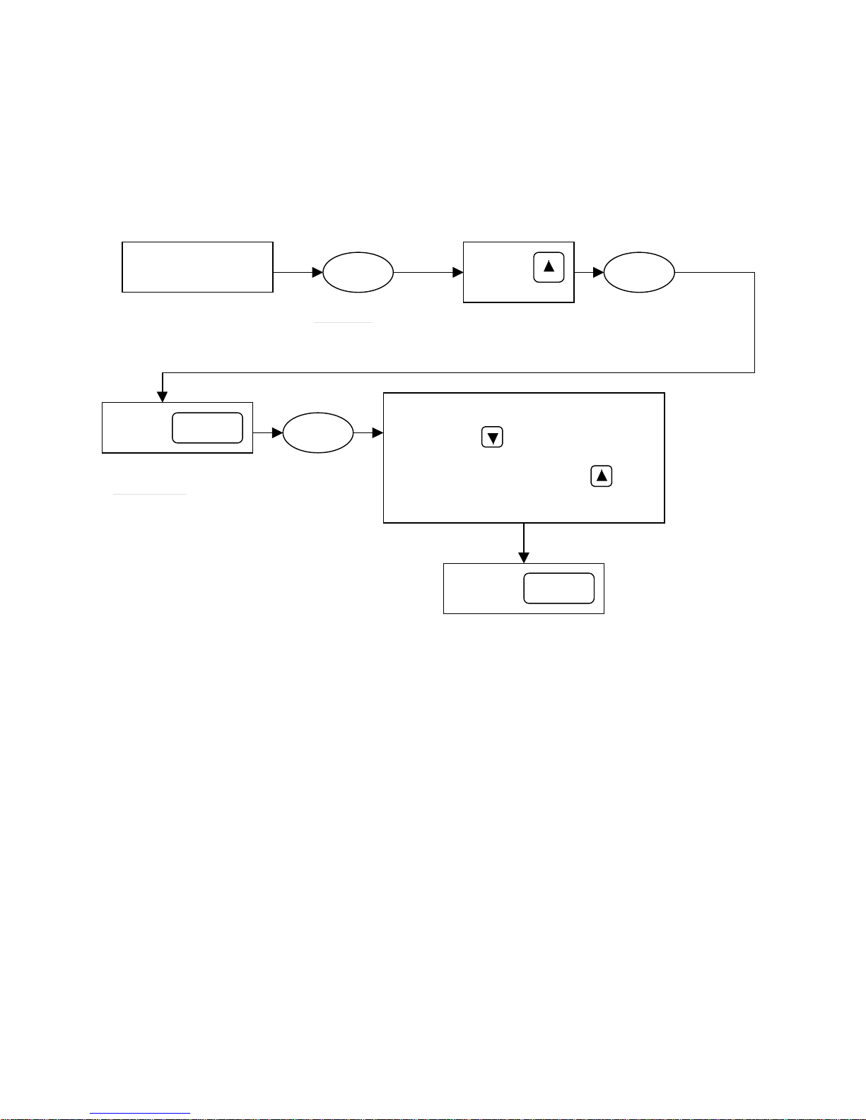
Section 2.3: Initial Setup Programming
2.3.1 Programming the Drive for a Specific Application
Initial setup programming involves a few easy steps. Follow the instructions shown in
Figure 2.3.1 below and your drive will be ready for operation.
Fig. 2.3.1: Programming Application Flowchart
Turn on the power
to the SV100 drive
[Function No. 1] – Speed 1 in
the
power up.
Press the
Key once
This will take you into the
Program Mode
*
The drive has now been programmed for its appropriate application. According to your
FUNC
“1” is
“0” is
initially
initially
displayed
displayed
10.0
User Level
1
is displayed at
Choose Application for Drive.
Traverse - Press once. “0” is displayed.
Hoist w/Load Brake - Leave “1” as is
Hoist without Load Brake - Press the key
Press the
up key
once.
Press the
Key once
MAC
(MAC)
[Function N o. 2–Mac] is
displayed
once.“2” is displayed.
FUNC
This saves the applic ation
selection
new selection, other related drive parameters have conveniently changed automatically
for quick programming.
See Table 2.3.1 for the function parameters that are affected by the above Macro Quick
Set procedure.
Note: If so desired, these values can be changed individually by entering the respective
access level and changing the function data to customize the drive to your specific
application.
31
Page 32
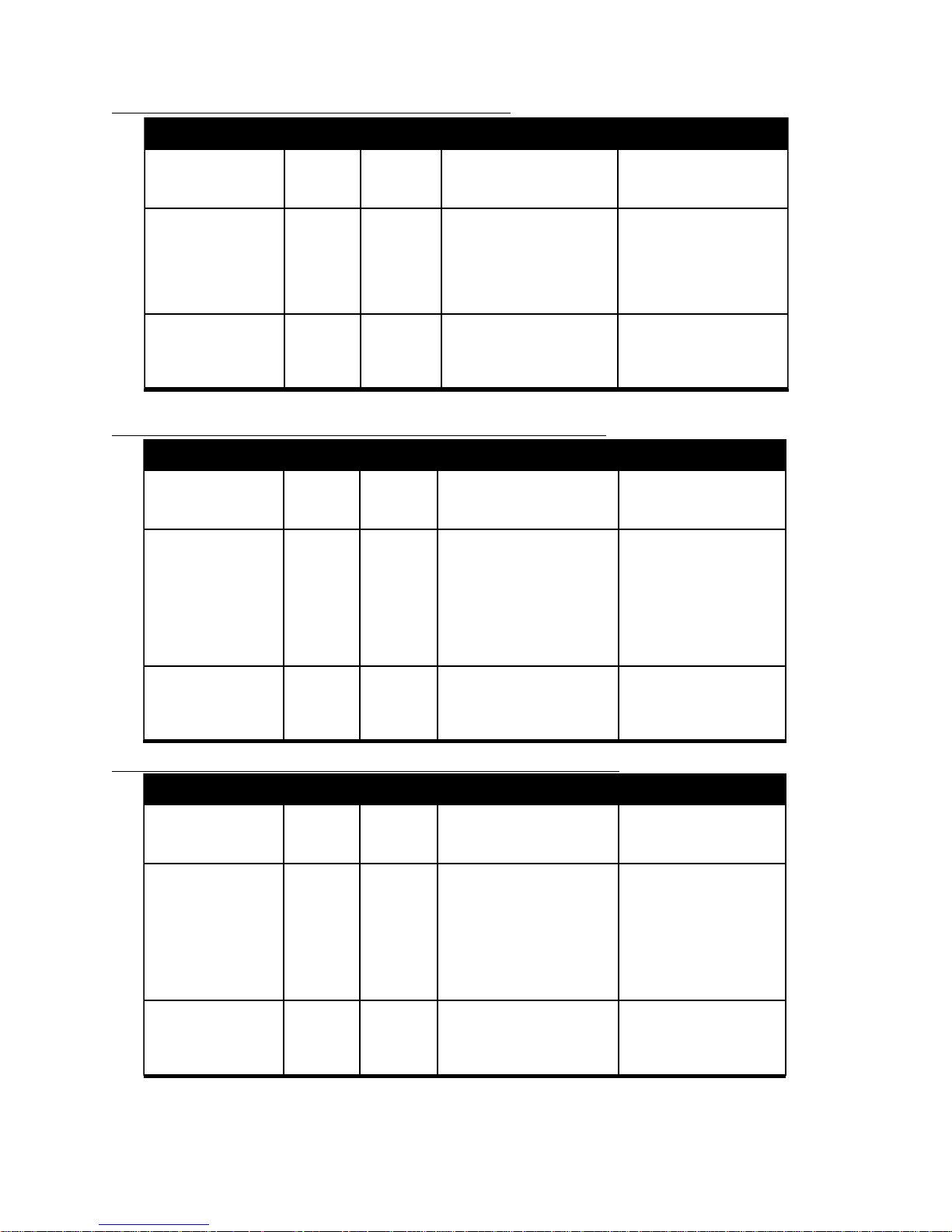
Table 2.3.1: Automatic Macro Settings For Application Selection (User Function 2)
Macro Set-Up for T raverse (Motion Definition “0”)
leveLsseccA .oNedoC yalpsiD noitpircseD ataDlaitinI
resU 3
7
8
ecivreS 2
3
21
31
81
02
decnavdA 62
03
43
05
S8S
CCA
CE8
2F
3F
21F
31F
81F
02F
62H
03H
43H
05H
noitceleSdeepS
emiTnoitareleccA
emiTnoitareleceD
nrettaPnoitareleccA
nrettaPnoitareleceD
ycneuqerFllewDgnitratS
emiTllewDgnitratS
ycneuqerFesaeleRekarB
edoMpotS
edoMnoitneverPllatS
emiTtimiLtnerrucrevO
tratseRFPI
elbanEgniggulPesreveR
Macro Set-Up for Hoist W/ Load Brake (Motion Definition “1”)
leveLsseccA .oNedoC yalpsiD noitpircseD ataDlaitinI
resU 3
7
8
ecivreS 2
3
21
31
51
61
81
02
S8S
CCA
CE8
2F
3F
21F
31F
51F
61F
81F
02F
noitceleSdeepS
emiTnoitareleccA
emiTnoitareleceD
nrettaPnoitareleccA
nrettaPnoitareleceD
ycneuqerFllewDgnitratS
emiTllewDgnitratS
tsooBeuqroTdrawroF
tsooBeuqroTesreveR
ycneuqerFesaeleRekarB
edoMpotS
.ces0.3
elbairaVyletinifnIpetS2:1
.ces0.3
evruCS:1
evruCS:1
.zH0.3
.ces1.0
.zH10.3
potSotpmaR:0
noitareleccAgniruD:1
.ces0.03
evitcA:1
evitcanI:0
elbairaVyletinifnIpetS2:1
.ces0.3
.ces0.3
evruCS:1
raeniL:0
.zH0.3
.zH5.0
%5
%2
.zH10.3
potSetaidemmI:2
decnavdA 62
03
43
05
62H
03H
43H
05H
edoMnoitneverPllatS
emiTtimiLtnerrucrevO
tratseRFPI
elbanEgniggulPesreveR
elbasiD:0
.ces1.0
evitcanI:0
evitcanI:0
Macro Set-Up for Hoist W/O Load Brake (Motion Definition “2”)
leveLsseccA .oNedoC yalpsiD noitpircseD ataDlaitinI
resU 3
7
8
ecivreS 2
3
21
31
51
61
81
02
decnavdA 62
03
43
05
NOTE: Typically, these settings will be appropriate for most applications however , they may be customized
by using the functions of the User, Service and Advanced Levels.
S8S
CCA
CE8
2F
3F
21F
31F
51F
61F
81F
02F
62H
03H
43H
05H
noitceleSdeepS
emiTnoitareleccA
emitnoitareleceD
nrettaPnoitareleccA
nrettaPnoitareleceD
ycneuqerFllewDgnitratS
emiTllewDgnitratS
tsooBeuqroTdrawroF
tsooBeuqroTesreveR
ycneuqerFesaeleRekarB
edoMpotS
edoMnoitneverPllatS
emiTtimiLtnerrucrevO
tratseRFPI
elbanEgniggulPesreveR
.ces0.3
.ces0.3
raeniL:0
raeniL:0
.zH0.3
.ces5.0
%5
%2
.zH10.3
elbasiD:0
.ces1.0
elbairaVyletinifnIpetS2:1
potSetaidemmI:2
evitcanI:0
evitcanI:0
32
Page 33
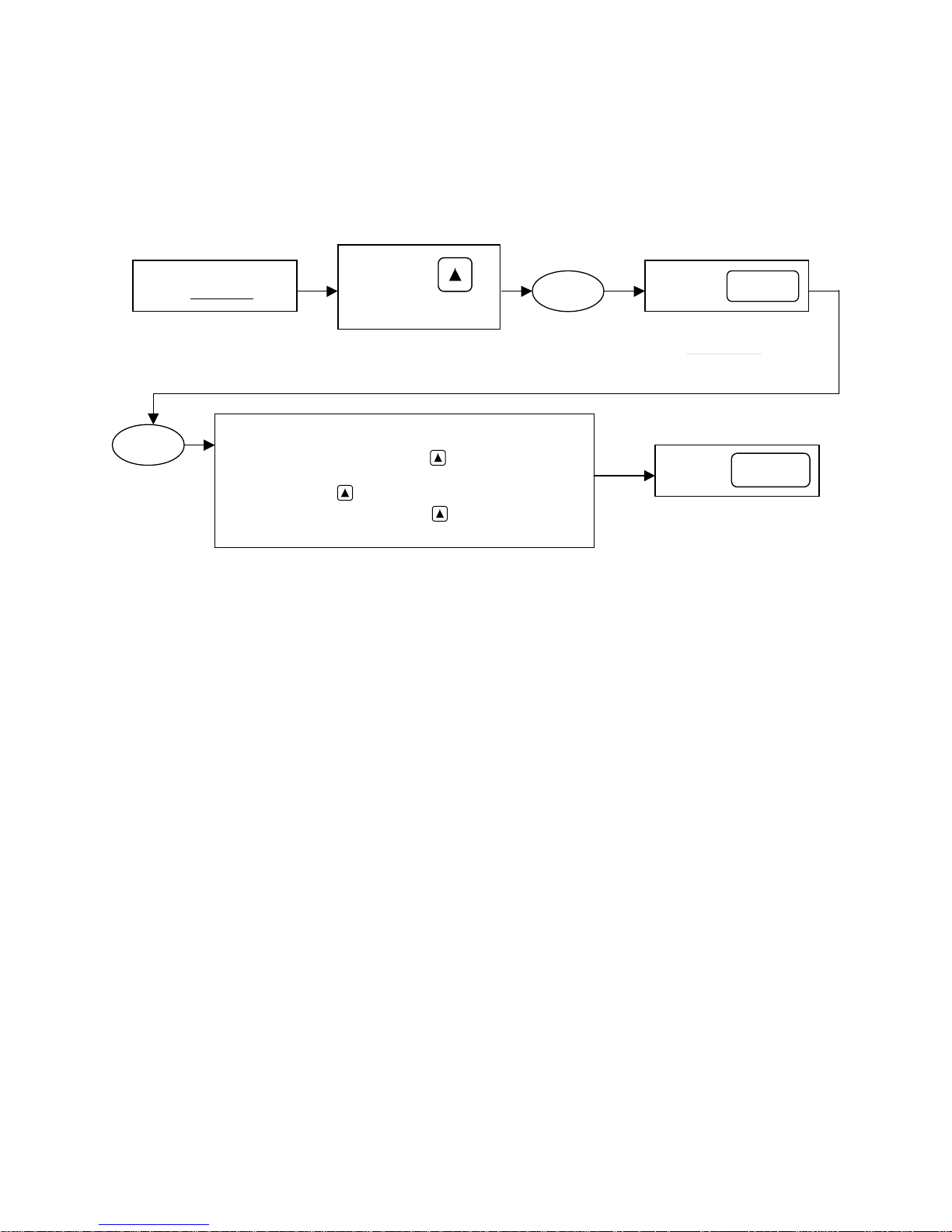
2.3.2 Programming the Speed Selection
The last step for initial setup programming is selecting the speed for the respective application.
Follow the flowchart shown in Figure 2.3.2 below.
Fig. 2.3.2: Speed selection flowchart
Currently you should
be in the
0
“0” is
initially
displayed
User Level
Choose the Speed Selection for your Application.
2 Speed - Leave “0” as is. Do not enter any value.
2 Step Infinitely Variable - Press the key once.
3 Speed - Press the key twice. “2” is displayed.
3 Step Infinitely Variable - Press the key three times.
Press the up
key until s8s is
displayed
“1” is displayed.
“3” is displayed.
S8S
[Function No. 3–sds] Speed
Selection
Press the
Key once
This will take you into the
Program Mode again
Press the
Key once
This saves the speed
selection
FUNC
FUNC
* The drive has now been programmed for its push button speed command. According to your
new selection, other related drive parameters have also changed automatically for quick
programming. See Table 2.3.2 for a list of parameters that have automatically changed.
33
Page 34
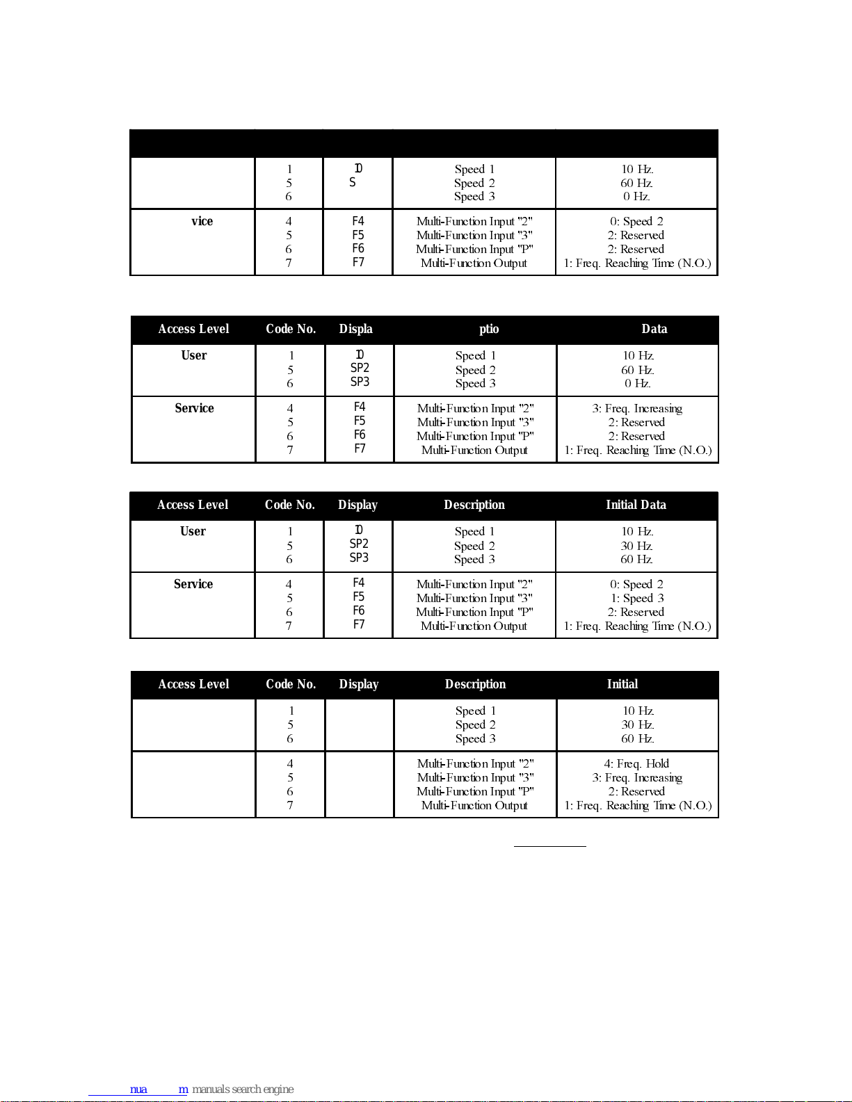
Table 2.3.2: Parameters Affected With Speed Selection Programming.
2 Speed
Access Le vel Code N o. Display De s cription I nitial Data
User
Service
2 Step Infinitely Variable
Access Le vel Code N o . Display Description I nitial Data
User
Service
3 Speed
Access Le vel Code N o . Display Description I nitial Data
User
Service
10
SP2
SP3
F4
F5
F6
F7
10
SP2
SP3
F4
F5
F6
F7
10
SP2
SP3
F4
F5
F6
F7
6SHHG
6SHHG
6SHHG
0XOWL) XQFWLRQ,QSXW
0XOWL) XQFWLRQ,QSXW
0XOWL) XQFWLRQ,QSXW 3
0XOWL) XQFWLRQ2XWSXW
6SHHG
6SHHG
6SHHG
0XOWL) XQFWLRQ,QSXW
0XOWL) XQFWLRQ,QSXW
0XOWL) XQFWLRQ,QSXW 3
0XOWL) XQFWLRQ2XWSXW
6SHHG
6SHHG
6SHHG
0XOWL) XQFWLRQ,QSXW
0XOWL) XQFWLRQ,QSXW
0XOWL) XQFWLRQ,QSXW 3
0XOWL) XQFWLRQ2XWSXW
+]
+]
+]
6SHHG
5HVHUYHG
5HVHUYHG
)UHT5HDFKLQJ7LPH12
+]
+]
+]
)UHT,QFUHDVLQJ
5HVHUYHG
5HVHUYHG
)UHT5HDFKLQJ7LPH12
+]
+]
+]
6SHHG
6SHHG
5HVHUYHG
)UHT5HDFKLQJ7LPH12
3 Step Infinitely Variable
Access Le vel Code N o . Display Description I nitial Data
User
Service
NOTE: The three speeds may be changed individually in the
10
SP2
SP3
F4
F5
F6
F7
6SHHG
6SHHG
6SHHG
0XOWL) XQFWLRQ,QSXW
0XOWL) XQFWLRQ,QSXW
0XOWL) XQFWLRQ,QSXW 3
0XOWL) XQFWLRQ2XWSXW
User level if so desired.
+]
+]
+]
)UHT+ROG
)UHT,QFUHDVLQJ
5HVHUYHG
)UHT5HDFKLQJ7LPH12
*The drive is now ready to run.
In the Appendix are timing graphs representing the dif ferent speed control options. To set
up the drive operation for Analog control see section 5.3.3.
34
Page 35

2.3.3 Drive Operation Checks
1. Test drive with an unloaded hoist.
2. Make sure the hoist electric motor brake is operating properly.
3. Run the hoist or traverse, and verify its correct operation in relation to direction of
movement versus pendant button pressed.
4. Check all limit switches for correct operation.
If the drive operates incorrectly please follow the troubleshooting charts of this manual, or
contact your SpaceVector Dealer for further assistance.
TM
35
Page 36

This page intentionally left blank.
36
Page 37

Chapter 3: Programming
Section 3.1: Passwords and Group Access Levels
3.1.1: Passwords
3.1.2: Entering a Password
3.1.3: Changing Passwords
Section 3.2: Programming Function Data
Section 3.3: Establishing Motor Parameters
37
Page 38

Section 3.1: Passwords and Group Access Level
3.1.1 Passwords
The SV100 allows you to program up to two passwords. The purpose of a password is to
prevent people from inadvertently changing important parameters found in the Service
and Advanced Levels. In order to change parameters in the Service or Advanced
Levels, you must first enter a password designated to the respective level. The User
Level does not require a password to change parameters.
When you first receive your drive, the programming permission level is initially setup for
Advanced Level. This means you can program parameters in all levels. The initial
the
password for all levels is (0). To help explain how passwords affect programming permission
levels, see Figure 3.1.1.
3.1.2 Entering a Password
When you first receive the SV100 drive, the initial password for all levels is (0). To help
explain how specific passwords affect each permission level of programming, follow Figure
3.1.1. It is assumed that the initial password of (0) has been changed to a (1) for
Level and a (2) for Advanced Level. If a password change is desired, see Changing a
Password, in Section 3.1.3 of this manual.
Service
3.1.3 Changing a Password
If a password change is desired in either the Service Level or the Advanced Level,
reference Figure 3.1.2.
Caution: Once you change your password, make sure it is written down where it can be
referenced at a later time if necessary.
38
Page 39
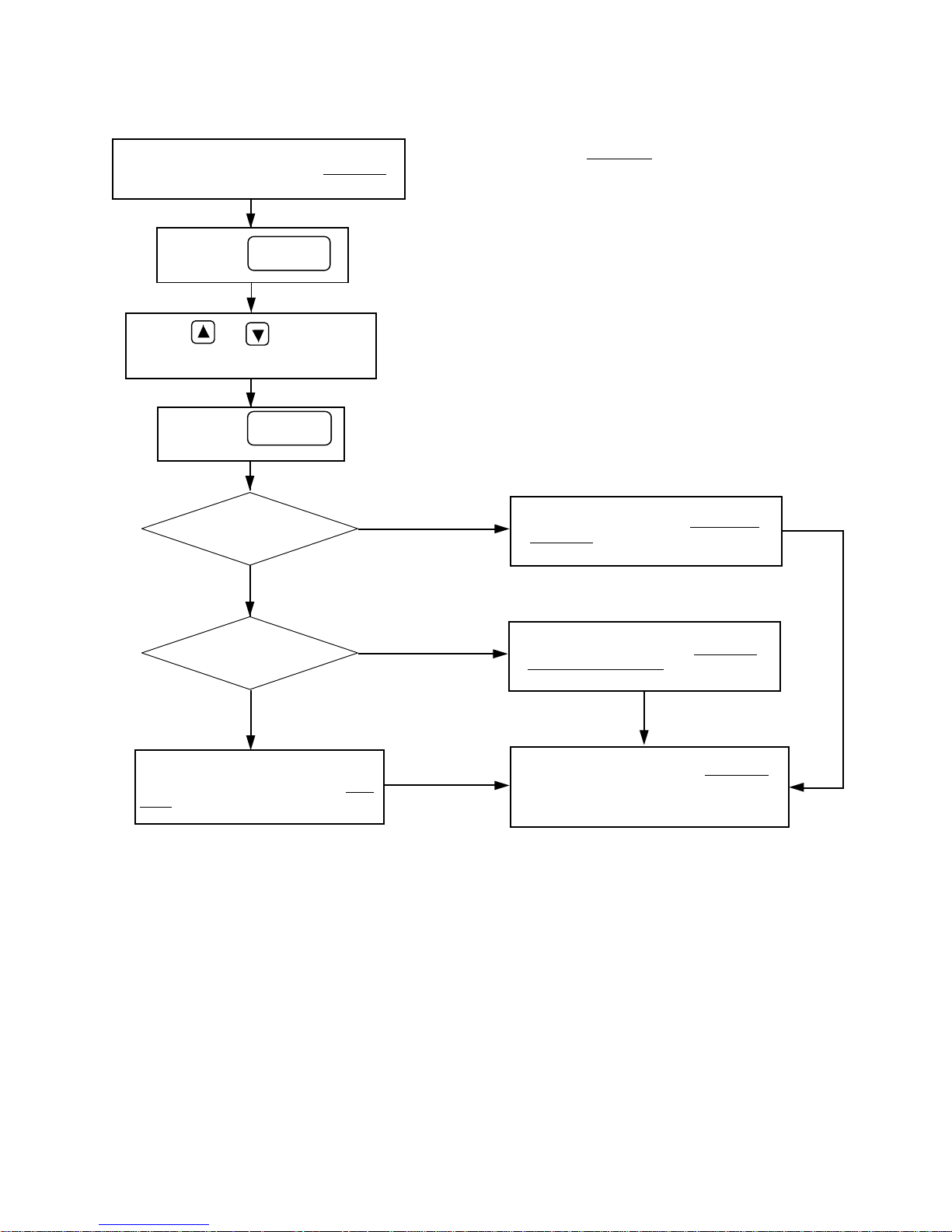
Fig. 3.1.1: Flowchart explanation for entering a password and its affect on programming
permissions.
Passwords
Get to [Function No. 15 - PAS] in the User Level
1 = Service Level
2 = Advanced Level
Press the
Key
Press the o r key to enter the
desired password value
Press the
Key
Does password
Does password
FUNC
FUNC
= (1)
No
= (2)
Yes
Yes
• This places you in programming mode
• This enters your selected password
Permission to program in the Service and
User Level is allowed.
Permission to program in the Advanced,
Service and User Level is allowed.
No
An incorrect password entry will
automatically place the user in the User
Level permission of programming.
[Function No. 14 - ACL] in the User Level
displays the current access level permission
of programming.
39
Page 40
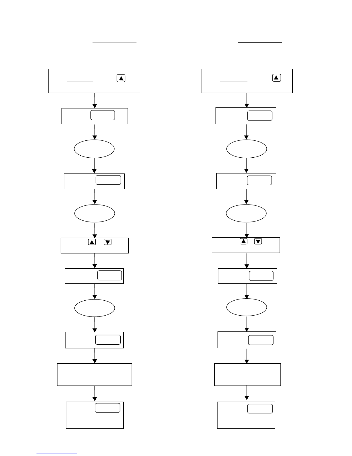
Fig. 3.1.2: Flowchart for changing passwords.
C
g
y
Changing the
Passw ord
Service Level
Changing the
Level
Password
Advanced
In th e User Level press the
key until ] is displayed.
Press the
key
FUNC
Press the
key
Pr ess th e or k e
to enter the old password
FUN
In the User Level press the
key until [] is displayed.
Press the
key
FUNC
Press the
key
Press the or ke y
to enter the old password
FUNC
40
Press the
key
FUNC
Press the
key
Enter the new password.
You may select any no.
Between 1 - 999
Press the
key to save the new
password
FUNC
FUNC
If you enter the wron
password, you will go back
PA1
to [
depending on which
function you are in.
] or [
PA2
],
Press the
key
FUNC
Press the
key
Enter the new password.
You may select any no.
Between 1 - 999
Press the
key to save the new
password
FUNC
FUNC
Page 41
Section 3.2: Programming Function Data
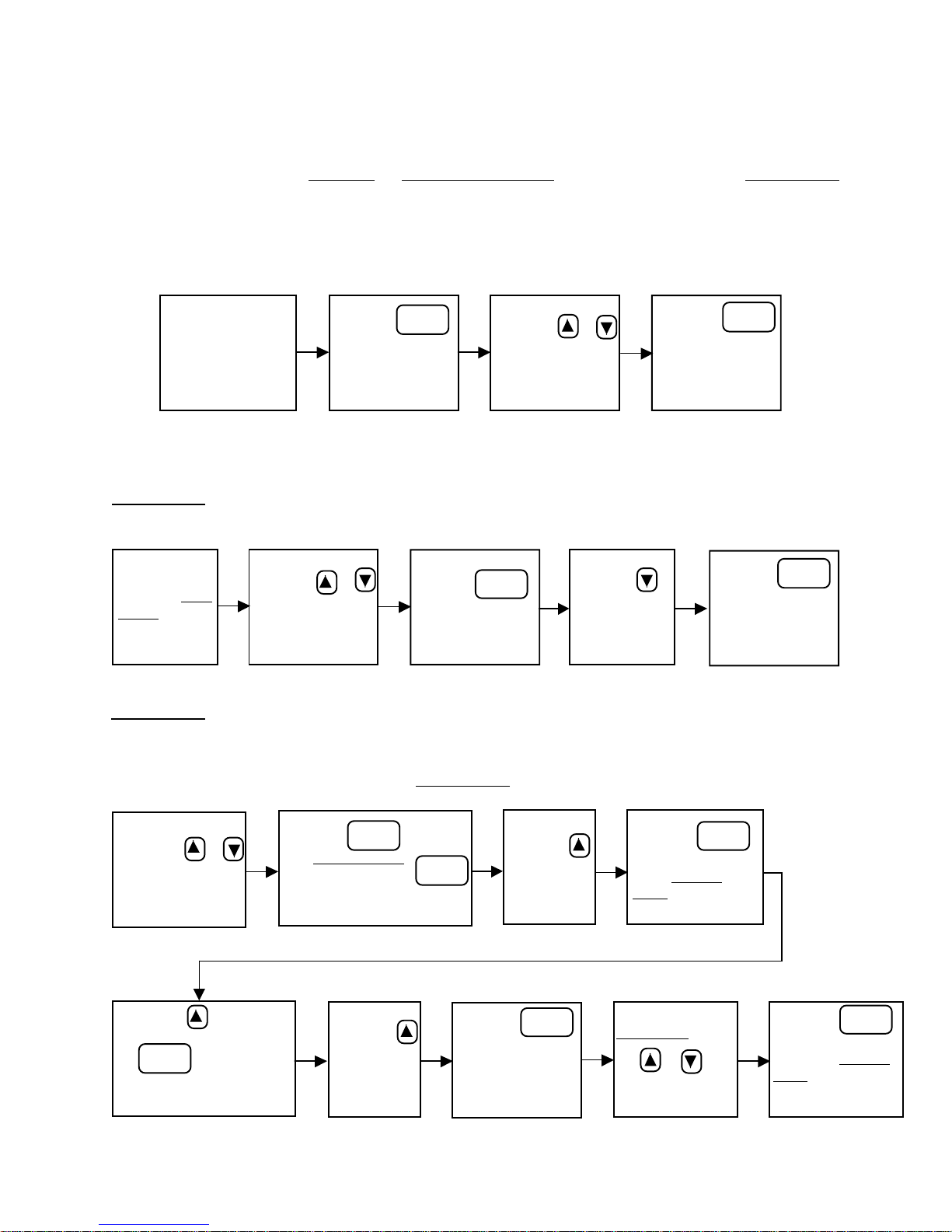
3.2.1 Customizing the Programming
Changing function data requires a few short steps. A password is required for changing
any function data in the Service or Advanced Levels. Changing data in the User Level
does not require a password. Figure 3.2.1 demonstrates how to change function data in
all levels.
Fig. 3.2.1: Changing function data in all levels.
Move to desired
function display as
seen in Table 2.2.1
Press the
key to go into
programming mode
FUNC
Press the or
keys until you have
the desired data
selection.
Press the
key to save your
data selection and
exit programming
mode.
FUNC
Below are a few examples of how to change function data. Use Table 2.2.1 for
reference.
Example 1:
Fig. 3.2.2: Change Speed 2 from 60.0 Hz. to 40.2 Hz.
Press the
key. This will save
your data change.
SP2 will be
displayed again
Go to the User
Level.
Press the or
keys until SP2 is
displayed.
Press the
key to go into
program mode. 60.0
is now displayed.
FUNC
Press the
key until 40.2 is
displayed.
Example 2:
Fig. 3.2.3: Store drive parameters into keypad.
FUNC
Assume that you are currently in the User Level and you have not entered a password.
Press the or
keys until PAS is
displayed.
Press the key until F22
appears. Now press the
key. You will be
FUNC
in program mode. “0” will
be displayed.
Press the key. Enter
your Service Level
password. Press
key again to enter password.
P AS will be displayed again.
FUNC
Press the
key until “1”
is displayed.
FUNC
Press the
key. This saves
your data selection. F22 will be
displayed again.
Press the
key until FU1 is
displayed.
FUNC
Press the
key. You will now be
in the Service
Level. F1 will be
displayed.
To get back to the
User Level, press
the or keys
until e6 is
displayed.
FUNC
Press the
key. This allows you
to exit the Service
Level. FU1 will be
displayed.
FUNC
41
Page 42
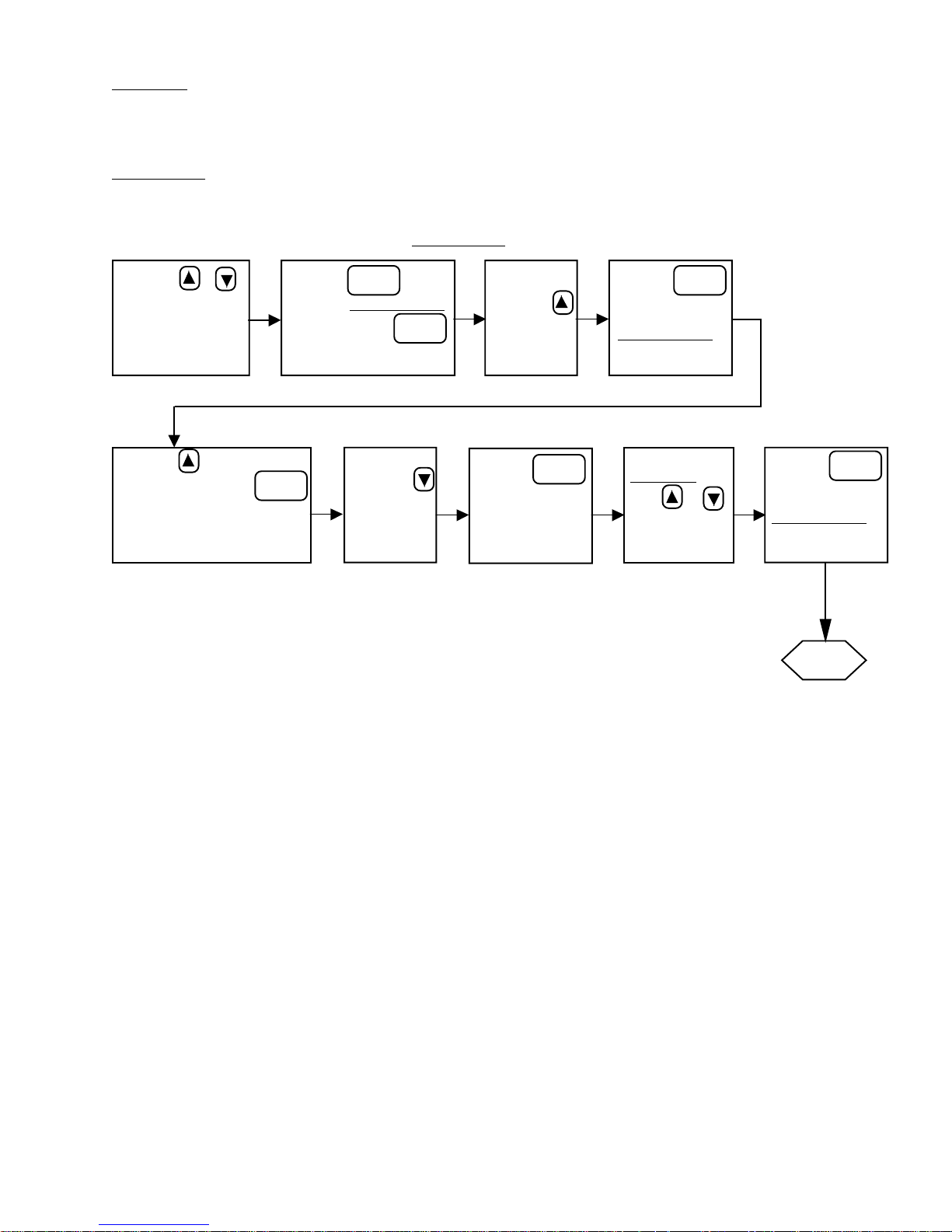
Caution: The next example shows how to change data in the Advanced Level. It is
recommended that only trained SpaceVector™ service personnel change data
in this level.
Example 3:
Fig. 3.2.4: Change the rated slip of the motor from 3.0 Hz to 2.5 Hz.
Assume that you are currently in the User Level and you have not entered any password.
Press your or
keys until PAS is
displayed
Press the key until H20
appears. Now press the
key. You will now be in
program mode. 3.0 will be
displayed.
Press the key.
FUNC
Enter your
password. Press
key again to enter
password. PAS will be
displayed again.
FUNC
Advanced Level
Press your
key until 2.5
is displayed
FUNC
Press the
key until FU2
is displayed.
Press the
key. This saves
your data selection.
H20 will be
displayed again.
FUNC
Press the
key. You will now
be in the
Advanced Level.
H1 will be displayed.
To get back to the
User Level, press
your or
key until 88 is
displayed.
FUNC
Press the
key. This allows
you to exit the
Advanced Level.
FU2 will now be
displayed.
FUNC
Finished
42
Page 43

Section 3.3: Establishing Motor Parameters
When establishing the motor parameters, assure the motor rated current does not
exceed the drive current rating. The default values for the Advanced Level functions
number 20, 21, and 22 may be set to values more closely representing the motor being
used with the drive. This is accomplished as follows:
1. Determine the motor synchronous speed and full load speed in revolutions
per minute.
2. Calculate the rated motor slip in Hertz using the following equations.
Rated Motor Slip (rpm) = [motor sync speed (rpm) – motor rated speed (rpm)]
60 Hz. x [rated motor slip (rpm)]
Rated Motor Slip (Hertz) =
3. Set Advanced Level function number 20 to the rated motor slip value
calculated in Hertz in step 2.
motor sync speed (rpm)
4. Obtain the motor rated current in amperes from the motor nameplate.
5. Obtain the drive current rating in amperes.
6. If the motor rated current obtained in step 4 is greater than the drive current
rating obtained in step 5, use a larger drive having a current rating equal to
or greater than that of the motor.
7. If the motor rated current obtained in step 4 is less than the drive current
rating obtained in step 5, set Advanced Level function number 21 to the
motor rated current obtained in step 4.
8. Calculate the minimum drive phase loss detection current.
Minimum Drive Current (Amperes) = 0.15 x [drive rated current (Amperes)]
9. Calculate the motor no load current.
Motor No Load Current (Amperes) = 0.30 x [motor rated current (Amperes)]
10.If the motor no load current calculated in step 9 is less than the minimum
drive phase loss detection current calculated in step 8, the drive cannot
detect phase loss and phase loss protection is no longer guaranteed. Consult the factory.
43
Page 44

11. If the motor no load current calculated in step 9 is greater than the minimum
drive current calculated in step 8, set Advanced Level function number 22 to
the motor no load current value calculated in step 9.
EXAMPLE:
5 HP drive having rated current of 8 ampere used with 1 HP motor having rated
current of 1.3 amp
Minimum drive current = 0.15 x 8 amp = 1.2 amp
Motor no load current = 0.3 x 1.3 amp = 0.39 amp
The no load motor current is less than the minimum phase loss detection current.
If the no load motor current is less than 15% of the drive rated current, the drive
may detect an erroneous phase loss and phase loss protection is no longer
guaranteed.
44
Page 45

Chapter 4: Troubleshooting
Section 4.1: Monitoring Current and Error Codes
4.1.1 Monitoring Current During Operation in
4.1.2 Error Code Monitoring
Table 4.1.1: Error Code Description
Table 4.1.2: Error Code Troubleshooting
Section 4.2: Problem Flowcharts
Section 4.3: Testing Power Components
Section 4.4: Pushbutton Pendant Test
User Level
45
Page 46
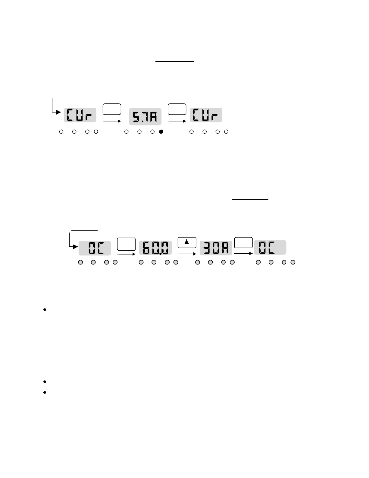
Section 4.1: Monitoring Current and Error Codes
4.1.1 Monitoring Current During Operation in User Level.
Go to [Function No. 4 - CUr] in the
User Level. Use Table 2.2.1 for reference.
[Function No. 4]
User Level
in
FUNC FUNC
RUN FWD REV SET RUN FWD REV SET RUN FWD REV SET
Current reading
during operation
4.1.2 Error Code Monitoring when Fault Takes Place in User Level
In this example, the fault reading is OC (Over Current).
[Function No. 10]
in User Level
Frequency
FUNC FUNC
Actual
current
at fault
RUN FWD REV SET RUN FWD REV SET RUN FWD REV SET RUN FWD REV SET
Pressing the STOP/RESET key at any point in the Fault Monitoring sequence will clear the fault
and allow the drive to be run again.
When a fault occurs the display automatically shifts to [User Function 10] which displays
the fault code. It is possible to monitor the frequency and current at the time of the fault.
To read this information, press the FUNC key, then the UP arrow key once. This shows
the frequency at the time the fault occurred. Press the UP arrow key again, the current
at the time of the fault occurred is displayed. This information is very helpful for
troubleshooting the cause of the fault, and will be requested if help from the factory is
sought. Press the FUNC key to go back to the fault display. While monitoring the fault
information, the 4 LED’s will flash.
It is possible to clear the fault by pressing the STOP/RESET key.
If there are no faults in the history , all three fuctions [User Functions 10, 1 1 and 12] will
display Ft1 until a fault occurs.
46
Page 47
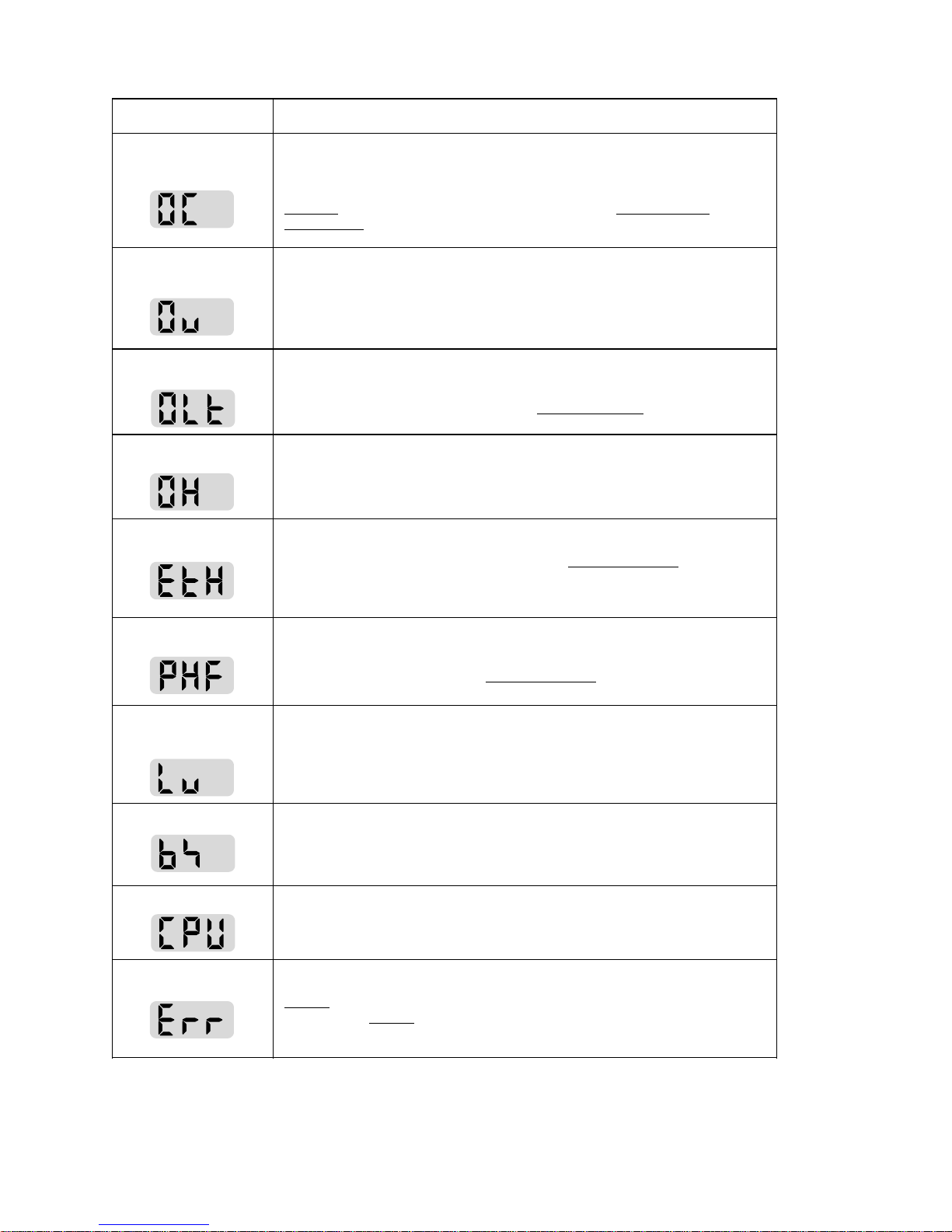
Table 4.1.1: Fault Code Description
y
y
y
Protective function Description
Over-current
protection
Over-voltage
protection
Current limit
protection
Heat-Sink overheat
EtH
Drive automatically cuts off its output, if the output current is over 200% of the
drive’s rated current.
Caution: Since there is a possibility of damage in the power module (IGBT),
DO NOT
Components in Chapter 4 for checking power modules.
Drive automatically cuts off its output if the regenerative energy from the
motor deceleration or generative load makes the DC voltage (DC Link
voltage) of the drive over 400V for 230V applications, or over 800V for 460V
applications.
Drive automatically cuts off its output if the current has over 180% of the
drives rated current during the current limit time setting. This fault is affected
by the value set in parameter H30 of the
When the drive heat-sink overheats, the temperature detection element
triggers the drive to automatically cut off its output. A failed cooling fan or a
foreign substance in the cooling fan can cause this.
Automatically shuts off the output of the drive if the condition meets the
function settings made in H31 and H32 of the
default settings, an ETH fault would occur if there is any over-current 100%
greater than the rated current and/or an overload capacity of 150% / 1 min.
restart the drive until properly checked. See Testing Power
Advanced Level
Advanced Level.
.
Under the
Phase fault
Low Voltage protection
BX protection
CPU error
Communication
Error
Occurs when one (1) or more output leads to the motor are opened.
Parameters H22 and H49 of the
responds to a phase loss.
A voltage drop to the drive can cause a lack of torque and/or motor
overheating. This fault automatically shuts off the output of the drive when
the DC voltage (DC Link Voltage) of the control circuit is below 200V for
230VAC applications or 400 volts for 460VAC applications.
This fault occurs if the BX terminal is being used. A BX fault shuts off the
output of the drive when the BX terminal is ON in the driving mode and
restarts when it is OFF.
Drive shuts off its output when there is an error in main CPU caused by
system noise. It is possible to clear the error by pressing STOP/RESET key.
Displa
ke
removing the keypad.
s the error in the communication between the main unit and the
pad, which has no influence on drive operation. It may be cleared b
Advanced Level
affect how the drive
47
Page 48

Table 4.1.2: Error Code Troubleshooting
Protective
Functions
Over-Current
Protection
Over-Voltage
Protection
Current Limit
Protection
(OLt)
Causes Solutions
1. Faster acceleration and
deceleration time than load inertia
requirements.
2. Larger load than the rated
capacity of the drive.
3. Driving while motor coasting.
4. Traverse worm gear speed
reducer using default stop mode,
F20
(1: Ramp to Stop)
1. Too short of deceleration time
compared t o load inertia.
2. Excessive regenerative energy on
the load side of drive.
3. Excessively hig h input vol tag e.
4. Noisy electrical environment.
1. Larger load than the drive’s rated
capacity.
2. Incorrect setting of the drive
capacity.
3. Incorrect setting of V/F pattern.
4. Bumping fixed objects.
1. Extend acceleration and deceleration
time (User Function 7 & 8).
2. Upgrade the drive capacity.
3. Start driving after motor stops.
4. Set
1. Extend deceleration time (User Function
2. Check Dynamic Braking Resistance.
3. Check the input power supply.
4. Correct input power or add 3%
1. Upgrade the motor and the drive
2. Reset the drive capacity (F8).
3. Adjust V/F pattern (F14 and/or H2 – H5).
4. Verify OLt time duration is adequate for
F20
, Stop Mode to (2: Immediate
Stop).
8).
impedance line reactor.
capacity in accordance with the load.
application.
Heat-Sink
Overheat
Electronic
Thermal Detection
(EtH)
Phase
Fault
Low Voltage
Protection
1. Failed cooling fan or foreign
object in the fan.
2. An abnormal condition in the
cooling system.
3. High ambient temperature.
1. Larger load than the rated current
of the drive.
2. Low ETH level.
3. Error in setting the drive capacity.
4. Error in setting the V/F pattern.
1. One of the output wires from (U,
V, W) to motor is open.
2. Setpoint of Motor No Load
Current is too high.
1. Low voltage input supply.
2. Larger load than the rated power
capacity of the drive.
3. Faulty magnetic mainline
contactor in power circuit.
1. Remove the foreign object, or replace the
cooling fan.
2. Check the heat-sink fins.
3. a. Lower the ambient temperature below
°
104
F (40° C)
b. Ventilate or air condition control
enclosure
1. Replace drive, or upgrade the capacity.
2. Adjust EtH level (H32). See Section
5.3.10.
3. Reset the drive capacity (F8).
4. Adjust V/F pattern (F14 and/or H2 – H5).
1. Make sure the motor leads are
connected tightly at drive terminals (U,
V, W) and at motor.
2. Verify motor data and adjust H20, H21
and H22 as necessary. See Section 3.3.
1. Check the input power voltage.
2. Upgrade power capacity.
3. Replace magnetic mainline contactor.
48
Page 49
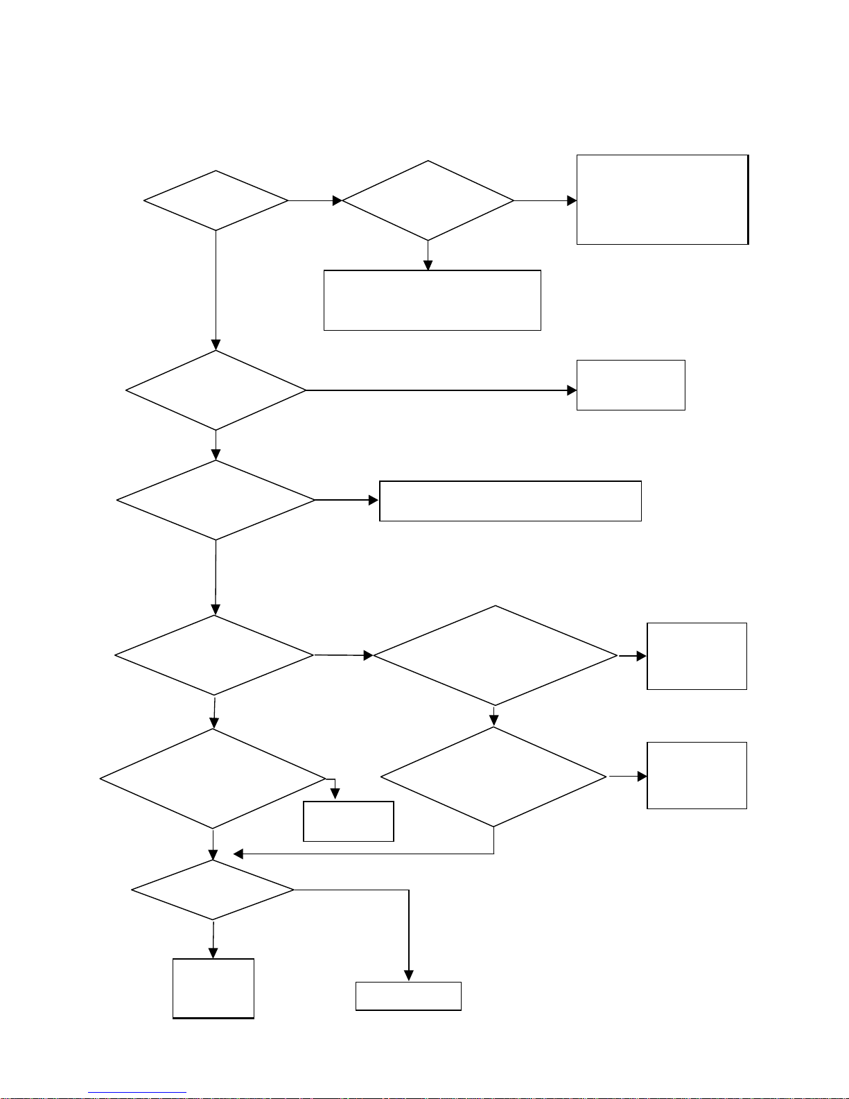
Section 4.2: Problem Flowcharts
Fig. 4.2.1: Motor Does not Run
No Yes
Is the display on? Is there input power?
Yes
• Check input fuses.
• Check circuit breakers.
• Is the main-line contactor energized?
No
Is RST or BX
terminal off?
Yes
Yes
Is [F1] set to
1: Terminal?
Check F and R terminal inputs. See Pushbutton
Pendant Test in Section 4.4.
No
Inverter trouble. Check keypad
or power components. See
Section 4.3 for Testing Power
Components
No
Check RST and
BX terminal inputs.
Is [H1] set to
0: Keypad?
Yes
Is Max. Freq. of Oper.
Set in [H11]
greater than 1
Voltage output
from U, V, W?
st
speed
Yes
Check output
wiring and
motor.
No
No
Adjust max.
frequency.
Call Factory
Is there analog signal between
V1-5G or I-5G inputs?
Yes
Is Max. Freq. of Operation
[H11] higher than [F9]?
YesYes
No
No
No
Analog signal
source trouble.
Set Max. Freq.
of Operation
higher than
Starting Freq. in
[F9].
49
Page 50
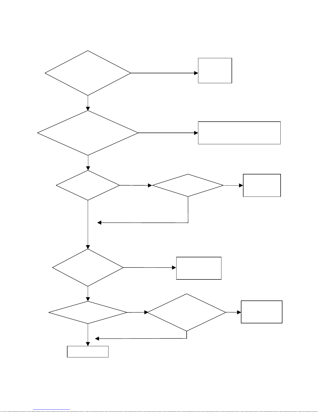
Fig. 4.2.2: Motor Speed is not equal to the Maximum Operational Frequency
Is the Max. Oper. Freq., [H11],
and Min. Oper. Freq., [H12],
set correctly?
Yes
Is the Max. Oper. Freq., [H1 1],
within the Freq. to Bypass,
[H13], or its bandwidth, [H14]?
No
Is [H1] set to
0: Keypad?
Yes
No
No
Yes
Adjust for
correct
frequencies.
Change Frequency to Bypass, [H13],
and/or Frequency to Bypass Bandwidth,
[H14].
Is there an
analog signal between
V1-5G or I-5G?
Yes
No
Analog signal
source trouble.
Is Acceleration
or Deceleration time
extremely long?
No
Is Stall Prevention Mode
selected in, [H26]?
No
Call Factory.
50
Yes
Yes
Is Stall Level, [H27],
Yes
Change Acceleration
or Deceleration Time,
[User Fcn’s 7 & 8],
according to load.
set correctly?
No
Change Stall
Level according
to load.
Page 51
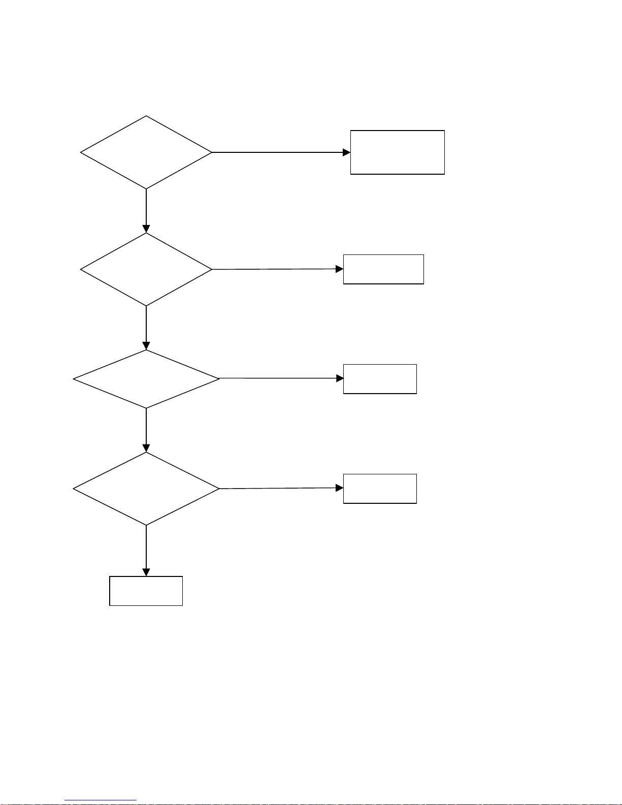
Fig. 4.2.3: Motor does not run smoothly
Is Acceleration or
Deceleration Time, [User Fcn’s
7 & 8],short?
No
Is Drive Cutoff Frequency
high in [F11]?
No
Are control signals fluctuating?
No
Yes
Yes
Yes
Increase Acceleration or
Deceleration Time,
[User Fcn’s 7 & 8].
Lower Drive Cutoff
Frequency [F11].
Check for noisy
electrical supply.
Is there balanced output
voltage at U, V, W, outputs?
No
Call Factory.
Yes
Check the motor.
51
Page 52
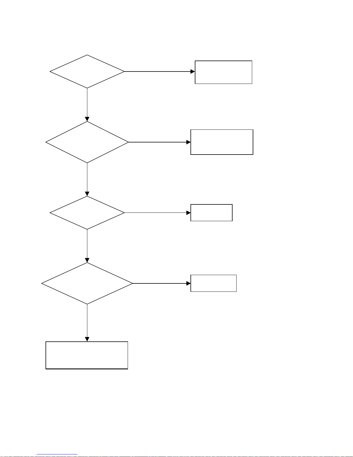
Fig. 4.2.4: Motor is abnormally hot
Yes
Is motor
overloaded?
No
Decrease the load or
increase motor capacity.
Yes
Does the motor run at
low speed regularly?
Use external cooling
system or adjust EtH
function in [H31] and
[H32].
No
No
Is output current
balanced?
Check the motor.
Yes
Linear
What is V/F Pattern [F14]? Call Factory.
User Defined
Change to Linear, if still having
problems call Factory.
52
Page 53
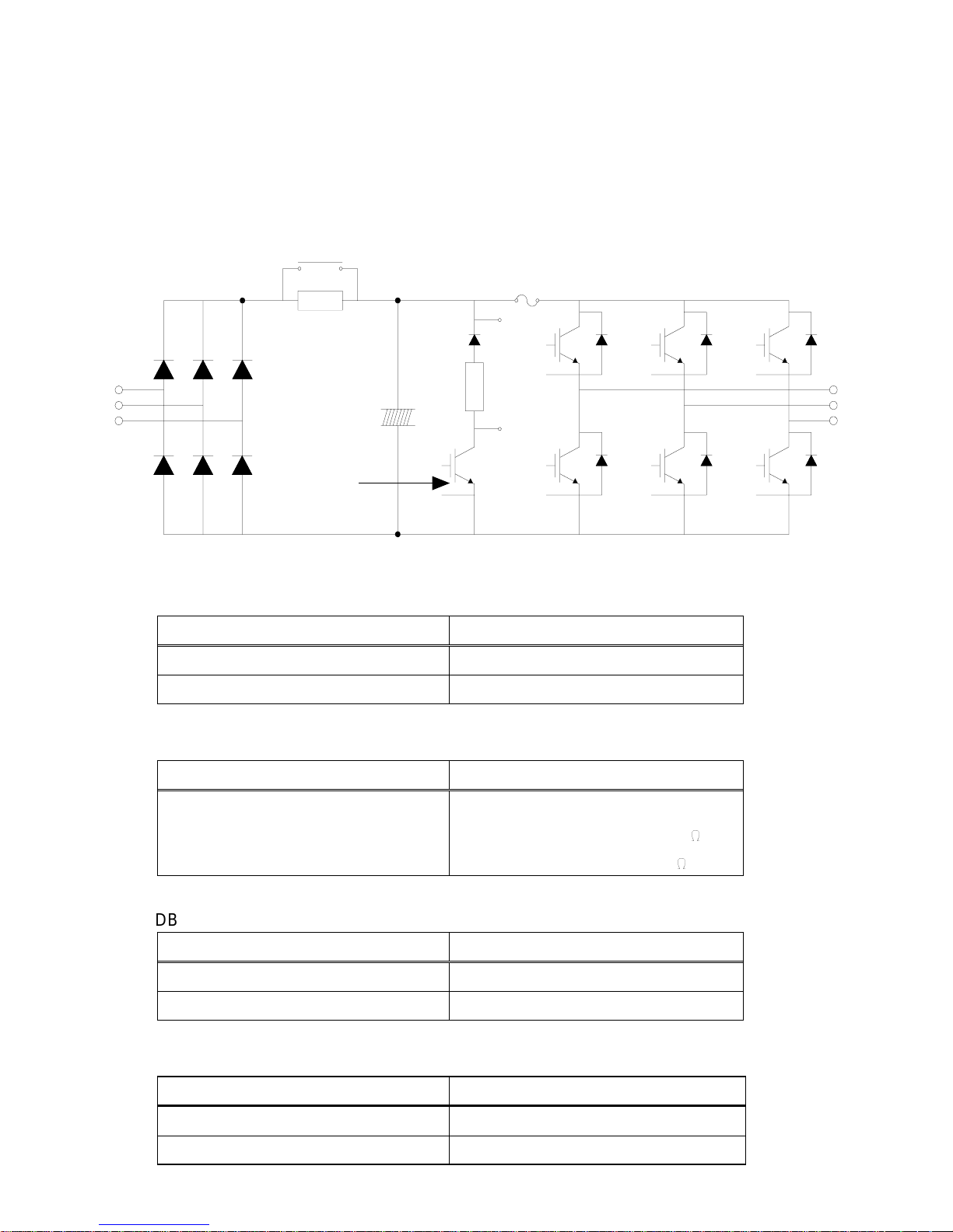
Section 4.3: Testing Power Components
4.3.1 How to Check Power Components
Before checking the power components, be sure to disconnect the AC input supply and
wait until the main electrolytic capacitor (P1-N) discharges. This may take several minutes.
Fig. 4.3.1: SV100 Power Components Functional Diagram
Magnetic Contactor
P
Charge Resistor
R
S
T
Electrolytic
Capacitors
Dynamic
Braking
IGBT*
P1
G
N
Fuse for 460 VAC
E
models only
B1
GuP
EuP
B2
GuN
EuN
GvP
EvP
GvN
EvN
GwP
EwP
GwN
EwN
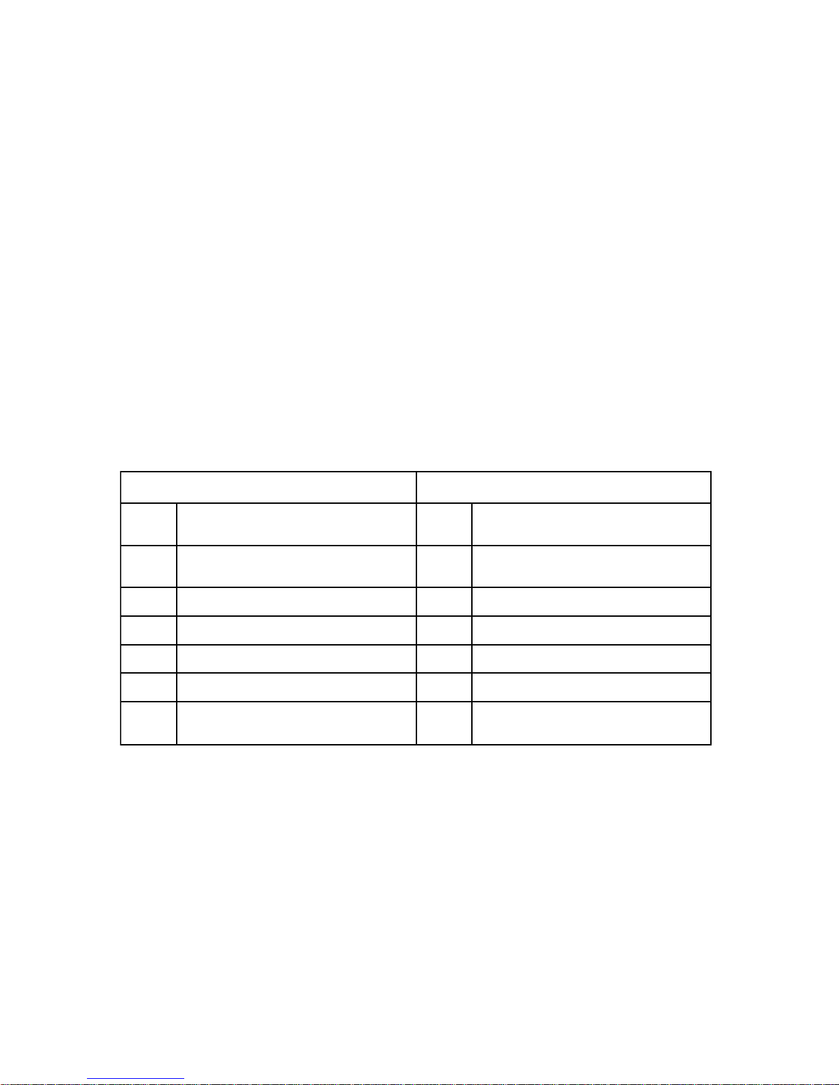
Table 4.3.1: Power Component Test Values - All resistance values measured with multi-meter
leads From + to -.
Input Diode Module Check
Check Points
From R, S, or T to P 50k ohms or more
From R, S, or T to N 50k ohms or more
Resistance to be Good
U
V
W
Charge Resistor Check
Check Points
From P to P1 Resistance depending on Models.
Resistance to be Good
Models 446485-07/08 50
All other models 100
:
DB (Dynamic Braking) IGBT*
Check Points
From B2 to N 50k ohms or more
From G to N A few kilo ohms
Resistance to be Good
Output Diode Module Check
Check Points
From U, V, or W to P1 and U, V, or W to N 50k ohms or more
Between Gate and Emitter of each IGBT A few kilo ohms
*IGBT = Isolated Gate Bipolar Transistor
Resistance to be Good
:
53
Page 54
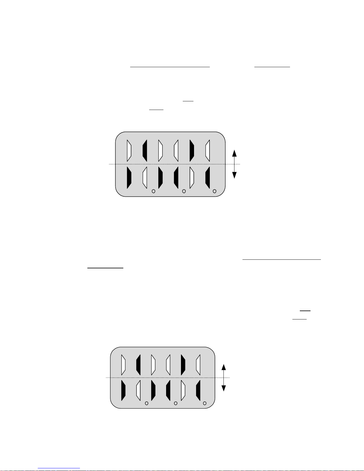
Section 4.4: Pushbutton Pendant Test
4.4.1 Interface Card Input and Output Test
The condition of the interface card can be monitored by using the 7-segment keypad
display . You must first go to Status of Input T erminal located in the User Level [Function
No.13 – InP]. Press the FUNC key and monitor the 7-segment display as you press the
respective pushbuttons. B4 is an dry contact output used for brake control and indicates
when the drive has activated the brake release. Example: If F and 3 terminals are
energized, Figure 4.4.1 shows the lights are ON for those respective terminals. R, B4, P
and 2 indicator lights are lit in the OFF row signifying that they are not energized.
Fig. 4.4.1: LED display for interface card test.
ON
OFF
R F B4 P 3 2
• Each column represents an input terminal of your interface card.
4.4.2 Control Board Input and Output Test
The condition of the input terminals and brake control output can be monitored by using
the 7-segment keypad display . Remove the interface card. Go to Status of Input T erminal
located in the User Level [Function No.13 – InP]. Press the FUNC key and monitor the
7-segment display as you close the connection between the respective inputs and CM on
the main control board. The inputs are sinking type DC inputs, so using a jumper wire
between the input and CM should cause the input to be on. MO is an open collector
output used for brake control and indicates when the drive has activated the brake release.
Example: If FX and P3 terminals are jumpered, Figure 4.4.2 shows the lights are ON for
those respective terminals. RX, MO, P3 and P1 indicator lights are lit in the OFF row
signifying that they are not energized.
Fig. 4.4.2: LED display for Control Board Input test.
ON
RX FX M O P3 P 2 P1
54
OFF
Page 55

Chapter 5: Function Code Information
5.1: User Function Levels
5.1.1 Frequency Output Monitor
5.1.2 Frequency Reference
5.1.3 Accel / Decel
5.1.4 Drive Operation Monitoring
5.2: Service Level Functions
5.2.1 Command Reference (RUN /STOP Selection)
5.2.2 Accel / Decel Patterns
5.2.3 Multi-Function Inputs
5.2.4 Multi-Function Output
5.2.5 Drive Model Selection
5.2.6 Frequency Settings
5.2.7 Brake Release Timing (Dwell Function)
5.2.8 V / F Pattern
5.2.9 Torque Boost
5.2.10 Output Voltage Adjustment
5.2.11 Frequency Detection
5.2.12 Braking
5.2.13 Upload / Download from Keypad and Set Defaults
5.3: Advanced Level Functions
5.3.1 Frequency Reference Source
5.3.2 User V / F Frequency
5.3.3 Analog Frequency Control
5.3.4 Operational Maximum / Minimum Frequency
5.3.5 Frequency to Bypass
55
Page 56

5.3.6 DC Braking
5.3.7 Motor Data
5.3.8 Auto Restart
5.3.9 Stall Prevention
5.3.10 Drive and Motor Protections
5.3.11 Instantaneous Power Failure and Speed Search
5.3.12 Restart After Reset
5.3.13 Carrier Frequency
5.3.14 Multi-Meter Output for Current, Voltage and Frequency
5.3.15 Motor Phase Loss
5.3.16 Reverse Plugging
56
Page 57

Section 5.1: User Level Functions
5.1.1 Frequency Output Monitor
The drive frequency can be monitored via Keypad and Multifunction output
terminals.
VIA KEYPAD
User Level [Function No. 1]: Displays Drive Frequency Output
The Keypad displays the drive frequency output to the motor once the RUN
command is initiated.
When the drive is not in RUN mode, the frequency display indicates the
programmed speed 1 frequency.
VIA FREQUENCY METER TERMINAL (See Section 5.3.14)
5.1.2 Frequency Reference
User Level [Function No. 1] Speed 1 (Factory Default: 10.0 Hz.)
Range: 0.0 – F9 Hz.
SP2 (User Level): Speed 2 (Factory Default: 60.0 Hz.)
Range: 0.0 – F9 Hz.
SP3 (User Level): Speed 3 (Factory Default: 0.0 Hz.)
Range: 0.0 – F9 Hz.
SdS (User Level): Speed Mode Macro (Factory Default: 1: 2 Step Infinitely Vari-
able)
Range: 0: 2 Speed
1: 2 Step Infinitely V ariable
2: 3 Speed
3: 3 Step Infinitely V ariable
The hoist speed references are set in the User Level. Speed 1 and 2 will be
applied when SdS is set to 0 or 1. Speed 1, 2, and 3 will be applied when SdS is
set to 2 or 3. The value of these speed points will be limited depending on the
value Maximum Frequency set in F9. Generally, the maximum frequency is set
to the maximum motor allowed output speed. The Rated Frequency of Motor
(Base Frequency) F10 is the motor rated speed in constant torque range. This
base frequency value should not be set higher than that of F9.
For frequency settings of F9, F10 and F11 see Section 5.2.6.
57
Page 58
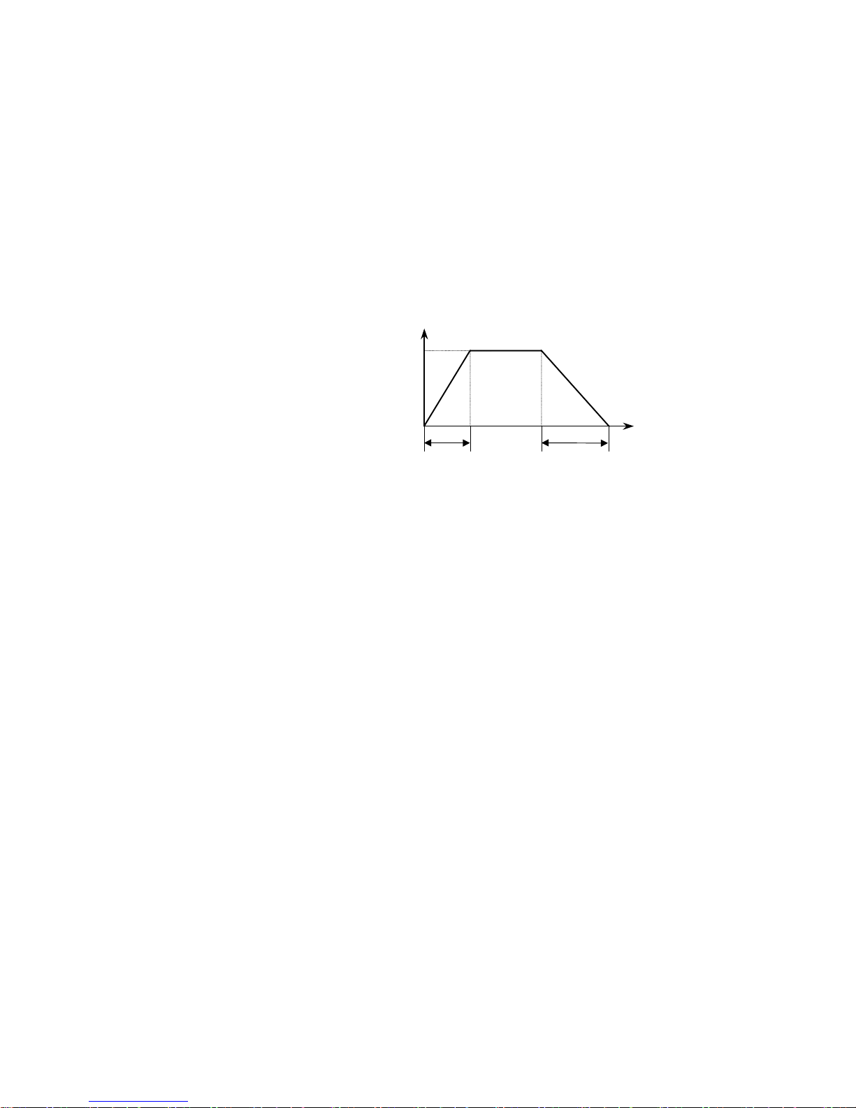
5.1.3 Accel / Decel
User [Function No. 7] - Acceleration T ime (Factory Default: 3.0 sec.)
Range: 0.0 – 999 sec.
User [Function No. 8] - Deceleration Time (Factory Default: 3.0 sec.)
Range: 0.0 – 999 sec.
Operator can program acceleration and deceleration times via keypad of the SV100
drive through the above parameters.
Fig. 5.1.1: Acceleration/Deceleration Time
Max. Freq.
LEVEL: User
DISPLAY: ACC, dEC
Acc. time Dec. time
Time
58
Page 59

5.1.4 Drive Status Monitoring
The drive operational status can be monitored via the drive keypad and Multi-Meter
output terminal.
FAULT HISTORY
User [Function Nos. 10, 11, 12]
Ft1 is the current fault if the drive is faulted and is not used when the drive is not
faulted. Drive keeps detailed fault information in two fault history parameters, plus a
memory location for the current fault, if there is one. Each fault history parameter
contains a fault code with drive status, drive output current and the frequency output
at the time of the fault. These conditions can be viewed by the using up and down
arrow keys of the keypad. See Section 4.1.2 for datailed instructions on all fault
code locations.
RESETTING A FAULT
The SV100 drive fault can be reset either from the keypad STOP/RESET button or
from the external fault reset terminal RST, or by turning power off, and back on after
approximately 3 min.
For the keypad reset, please refer to Section 4.1.2.
STATUS OF INPUT AND OUTPUT TERMINAL
Drive input terminal status and brake control output status can be monitored in User
Function No. 13 [InP]. This feature is a useful feature for drive trouble-shooting.
The status of selected terminals are displayed on the LED display. See Section 4.4
for a description of this feature.
SOFTWARE VERSION
vEr: Software Version
Example: H2C: Lift-Tech Software Version #2,
This is the software version of the SV100 drive
PASSWORDS
See Section 3.1 for an explanation of this feature.
59
Page 60
Section 5.2: Service Level Functions
5.2.1 Command Reference (RUN/STOP Selection)
The drive can receive its command sequence (RUN, STOP, FWD, REV), via
external terminals.
F1:
Run/Stop Mode (Factory Default: 1: Terminal)
Range:0: Keypad
1: Terminal
KEYPAD
The JOG function works via the keypad only. See Section 2.2.3 for instructions on
use.
TERMINAL
Each of the sequence commands can be initiated via external controls, such as
pushbuttons.
Table 5.2.1: Drive Input Terminals
slanimreTtupnIdraoBlortnoCevirDdraCecafretnI
xF
xR
TSR.gnikniSCDV42.teseRteseRtluaF
dnammoCnoitceriDdrawroF/pU
.gnikniSCDV42.lanimreT
dnammoCnoitceriDesreveR/nwoD
.gnikniSCDV42.lanimreT
F
R
dnammoCnoitceriDdrawroF/pU
.gnicruoSCAV021.lanimreT
dnammoCnoitceriDesreveR/nwoD
.gnicruoSCAV021.lanimreT
1P.gnikniSCDV42tupnInoitcnuF-itluM2 .gnicruoSCAV021tupnInoitcnuF-itluM
2P.gnikniSCDV42tupnInoitcnuF-itluM3 .gnicruoSCAV021tupnInoitcnuF-itluM
3P.gnikniSCDV42tupnInoitcnuF-itluMP .gnicruoSCAV021tupnInoitcnuF-itluM
MC
.stupnI
gnikniSCDV42roflanimreTnommoC
C
stupnI
5.2.2 Accel / Decel Patterns
F2: Acceleration Pattern (Factory Default: 1: S Curve)
Range: 0: Linear
1: S Curve
F3: Deceleration Pattern (Factory Default: 0: Linear)
Range: 0: Linear
1: S Curve
These values are set with Motion Definition Macro, see Table 2.3.1. The user can
select different acceleration and deceleration patterns for smoother hoist or traverse
ramping.
gnicruoSCAV021roflanimreTnommoC
60
Page 61
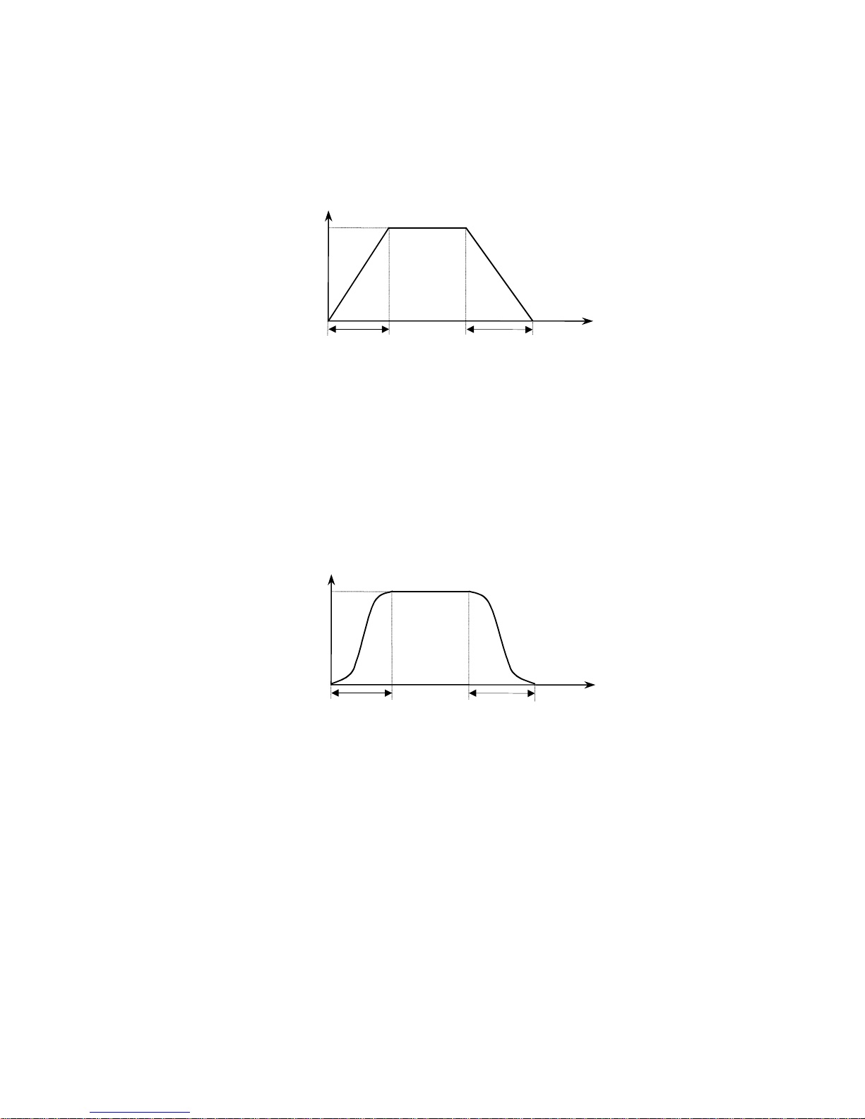
LINEAR
The linear pattern is generally good for hoists without a mechanical load brake with
sufficient output torque.
Fig. 5.2.1: Linear Acceleration/Deceleration Curve
Output freq.
Acceleration Deceleration
time
S-CURVE
This pattern is used to initiate smooth ramping during an Acceleration or
Deceleration sequence. This pattern is suitable for hoists with a mechanical
load brake, creating less brake wear.
Fig. 5.2.2: S-Curve Acceleration/Deceleration Curve
Output freq.
Acceleration Deceleration
time
5.2.3 Multi-Function Inputs
The SV100 drive is equipped with 3 Multi-Function Inputs, which determine how the
drive reacts to inputs from the controls. They can be configured to be Speed 2,
Speed 3, Frequency Increasing, Frequency Hold, Immediate Stop, Ramp to Stop, or
Low Speed.
F4, F5, F6: Multi-function Input (Factory Default: See Section 2.3.2)
Range:0: Speed 2
1: Speed 3
2: Reserved
3: Frequency Increasing
4: Frequency Hold
5: Immediate Stop
6: Ramp to Stop
7: Low Speed Limit Switch
61
Page 62

Speed 2: With an input of either run command (F or R) the drive will run at the
programmed speed of SP2 [User Function 5].
Speed 3: With an input of either run command (F or R) and input SP2 the drive will
run at the programmed speed of SP3 [User Function 6].
Reserved: Reserved for future use.
Frequency Increasing: For use with either 2 Step Infinitely Variable or 3 Step Infinitely
Variable, causes drive output to increase when there is a run command (F or
R). If 3 Step Infinitely Variable then Frequency Hold is required also.
Frequency Hold: Used as the second detent on a pushbutton for 3 Step Infinitely
Variable control. Causes the drive frequency output to hold at last value.
Immediate Stop: When a Multi-Function Input is programmed for this operation and the
Normally Closed input opens, the drive output immediately stops. (Default for
hoist control).
Ramp to Stop: When a Multi-Function Input is programmed for this operation and the
Normally Closed input opens, the drive output ramps to a stop. (Default for
traverse control). NOT RECOMMENDED FOR HOIST MOTION.
Low Speed Limit Switch: When a Multi-Function Input is programmed for this
operation and the Normally Closed input opens, the drive output ramps to the
value in User Function 9 (LSP).
5.2.4 Multi-Function Output
The SV100 drive is equipped with a Normally Open contact between B3 and B4 on
the interface card. It can be configured to be frequency detection, motor stall, overload, low voltage indicator, and Run /Stop indication.
F7:Multi-function Output (Factory Default: 1:Freq. Reach N.O.)
Range:0: Frequency Reaching Time (Normally Closed) (See Section 5.2.1 1)
1: Frequency Reaching Time (Normally Open) (See Section 5.2.11)
2: Stall Operation Signal (See Section 5.3.9)
3: Overload Signal (See Section 5.3.10)
4: Low Voltage (LV fault) Signal
5: Run/Stop Signal
STALL OPERATION SIGNAL
Multi-Function Output terminals B3 and B4 programmed to 2: Stall Operation Signal
will close when the drive’s Stall Prevention control is activated. As there is only one
Multi-Function Output available, there will be no brake control, therefore it is advised
this output function NOT be used in hoist applications, this has no effect on the drive
Stall Response.
62
Page 63
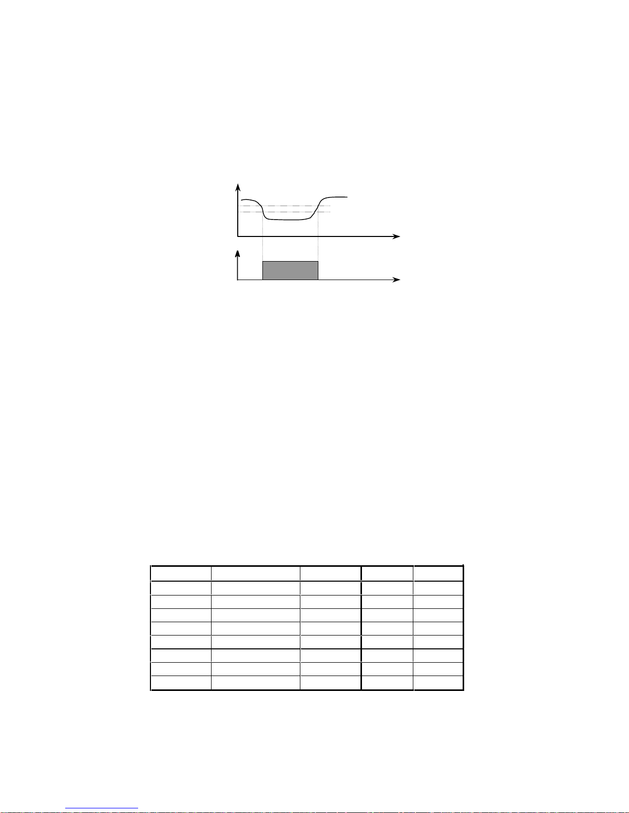
LOW VOLTAGE SIGNAL
Multi-Function Output terminals B3 and B4 programmed to 4: Low Voltage (LV fault)
Signal will close when the DC Link voltage falls below the low voltage level of the
drive (200VDC for 230 VAC, and 400VDC for 460 VAC drives).
Fig. 5.2.3: Under-voltage Fault Signal
DC link voltage
230V
200V
time
B3, B4
B3 - B4
ON
RUN / STOP SIGNAL
The Multi-Function Output terminals B3 and B4 programmed to 5: Run/Stop Signal
will close when the drive changes from a stop condition to a run condition.
5.2.5 Drive Model Selection
F8:
Range:See Table 5.2.2 below.
Drive Model Selection (Factory Default: See Table 5.2.2)
The drive model selection for each drive is preset at the factory. This parameter
must be set correctly in order for the drive to calculate its output current. Table 5.2.2
cross references the drive model number, horsepower, and voltage rating, and lists
the default values for Rated Motor Current (H21) and No Load Motor Current (H22).
Table 5.2.2: SV100 Part Number Cross Reference to Drive Model Selection
Model No. Description Part No. FLA (H21) NLA (H22)
1.2 1 HP - 230 Volt 446485-01 4.2 0.6
2.2 2 HP - 230 Volt 446485-02 6.8 1.8
3.2 3 HP - 230 Volt 446485-03 9.6 2.8
5.2 5 HP - 230 Volt 446485-04 15.2 4.4
1.4 1 HP - 460 Volt 446485-05 2.1 0.3
2.4 2 HP - 460 Volt 446485-06 3.4 0.9
3.4 3 HP - 460 Volt 446485-07 4.8 1.4
5.4 5 HP - 460 Volt 446485-08 7.6 2.2
63
Page 64
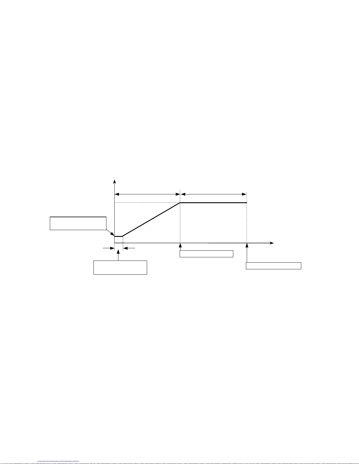
5.2.6 Frequency Settings
F9:
Maximum Frequency of Operation (Factory Default: 60.0 Hz.)
Range:40.0 - 120 Hz.
F10: Rated Frequency of Motor (base frequency)
Range:40.0 – F9 Hz. (Factory Default: 60.0 Hz.)
F11: Drive Cutoff Frequency (Factory Default: 0.50 Hz.)
Range:0.01 - 5.00 Hz.
If the base frequency is set at 40 Hz and the maximum frequency is set at 60 Hz.,
the motor will run up to 40Hz in Constant Torque mode and up to 60 Hz. in Constant
Horsepower mode. The Drive Cutoff Frequency set in F11 provides the initial
frequency output of the drive. Setting this value too high can result in increased
starting torque demand from hoist load resulting in an overcurrent (OC) fault.
Fig. 5.2.4: Motor Frequency Relationship Diagram
Output volt.
Constant Torque range
100%
Starting Dwell
Frequency F12
Constant Horsepower range
Starting Dwell Time
F13
Base freq. F10
Output freq.
Max freq. F9
64
Page 65
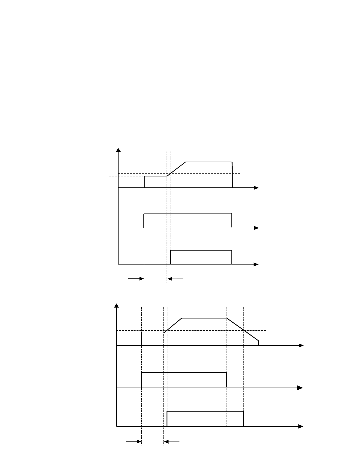
5.2.7 Brake Release Timing (Dwell Function)
q
F12: Starting Dwell Frequency (Factory Default: 3.0 Hz.)
Range:0.0 – F9 Hz.
F13: Starting Dwell Time (Factory Default: 0.5 sec. Hoist.)
Range:0.1 sec. – 10.0 sec. 0.1 sec. Traverse)
The dwell function is used for torque proving before the brake is released. The
current is applied to the motor during the Starting Dwell Time [F13] before releasing
the brake.
Caution: Dwell frequency should be set to the slip frequency of the motor if the slip
is greater than 3 Hz. To calculate slip frequency, see Section 3.3.
Fig. 5.2.5: Brake Release Timing (Hoist)
Brake Release Freq.
F12: Starting Dwell Freq.
Fout
F18:
F or R input
Brake Release (B3 – B4)
Starting Dw ell Time
F13:
Fig. 5.2.6: Brake Release Timing (Traverse)
F12: Starting Dwell Freq.
Fout
F or R input
Brake Release Freq.
F18:
D rive Cu to ff F re
F11:
time
tim e
.
Brake Release (B3 – B4)
Starting D well Time
F13:
tim e
65
Page 66
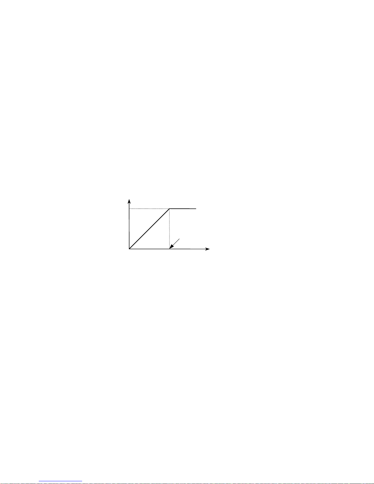
5.2.8 V/F Pattern
F14: Volts per Hertz Pattern (Factory Default: 0: Linear)
Range:0: Linear
1: Reserved (DO NOT USE)
2: User Defined V/F
Depending on the applications, different Volt/Hertz patterns can be selected. In
User Defined V/F, various points of V/F ratios are programmed for the best output
result. Please contact the factory for more information.
LINEAR [Constant Torque Applications]
This pattern is best suited for Constant Torque applications like Hoist/Crane. This
Linear pattern has a V/F ratio that is constant throughout the entire frequency range
up to the drive base frequency.
Fig. 5.2.7: Linear V/F Diagram
Output volt.
100
%
Base frequency
Output freq.
USER V/F
The User Pattern can be used for special purpose applications. There are two V/F
points that can be programmed between the starting frequency and the base
frequency. See Fig. 5.2.8.
H2: User V/F Frequency 1 (Factory Default: 5.0 Hz.)
Range 0.0 - F9 Hz.
H3: User V/F V oltage 1 (Factory Default: 16 %)
Range 0 - 100 %
H4: User V/F Frequency 2 (Factory Default: 30.0 Hz.)
Range 0.0 - F9 Hz.
H5: User V/F V oltage 2 (Factory Default: 50 %)
Range 0 - 100 %
66
Page 67
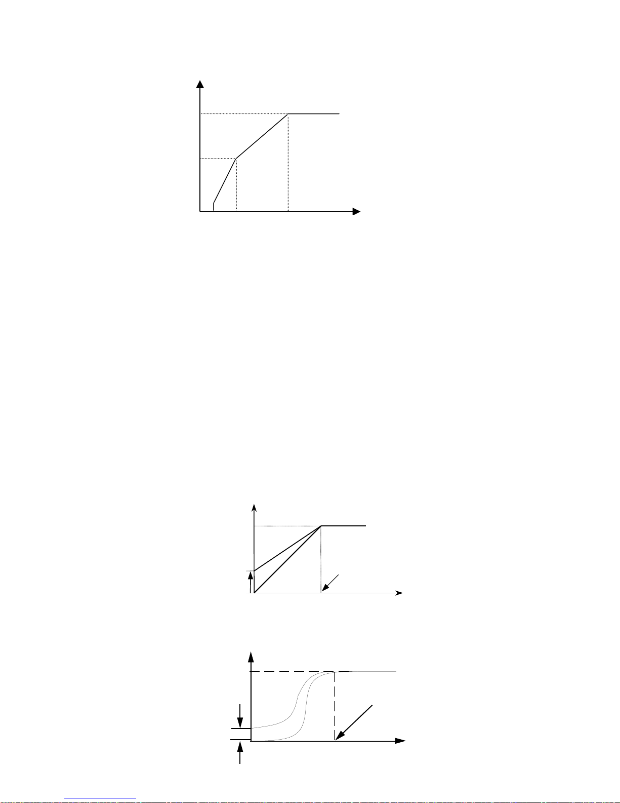
Fig. 5.2.8: User V/F Pattern
voltage
H5
H3
H2
H4
frequency
5.2.9 Torque Boost
F15: Forward Torque Boost (Factory Default: 5%)
Range:0 - 20 %
F16: Reverse Torque Boost (Factory Default: 2%)
Range:0 - 20 %
The forward and reverse torque boost value can be set separately. This function is
used to increase the output voltage to the motor at low speeds for a higher
volts/hertz ratio, resulting in a much higher starting current output to the motor. This
is for loads that require relatively higher torque than normal starting torque.
Note: If the torque boost is set too high an Overcurrent fault may occur. When this
occurs reduce the Torque Boost values.
Fig. 5.2.9: Torque Boost in Linear Pattern
Output volt.
Boost value
Fig. 5.2.10: Torque Boost in S-Curve Pattern
Output Voltage
Boost value
100%
Base frequency
Output freq.
100%
Base Frequency
Output Frequency
67
Page 68
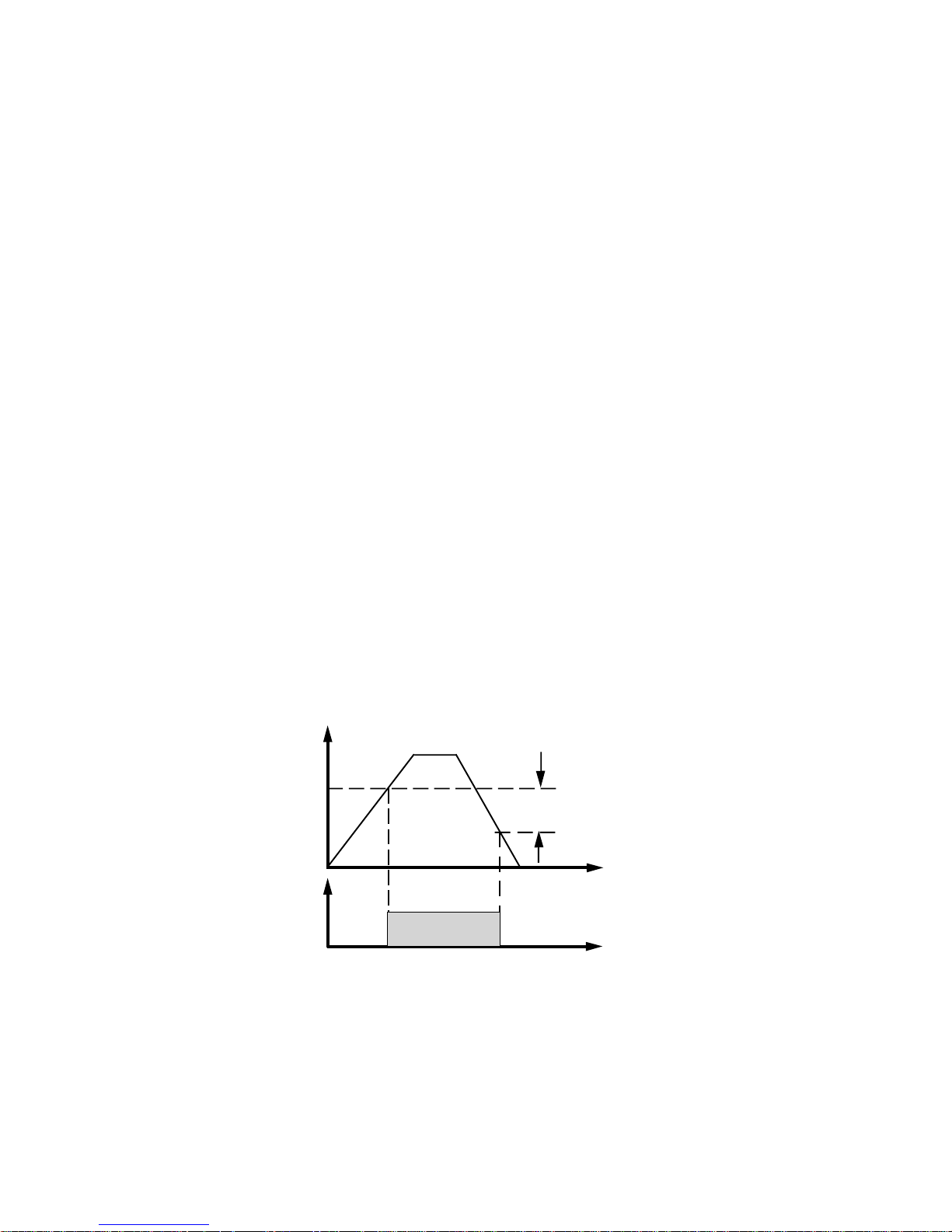
5.2.10 Output Voltage Adjustment
F17:
Output V oltage Adjustment (Factory Default: 100%)
Range:50-110%
Inverter output voltage can be adjusted to motor rated input voltage. This function is
useful when rated motor voltage is lower than the rated inverter output voltage.
110% means over-modulation in PWM causing a higher output voltage compared to
100% of rated output voltage.
5.2.11 Frequency Reaching Signal
This function is used to operate the electric motor brake. The output signal is generated once the drive reaches output frequency level for enough flux gain in the motor
and ready to release the brake. See Section 5.2.4 for more information regarding
the brake and the Multi-Function Output.
F18:
Range:0.01 - F9 Hz
Brake Release Frequency (Factory Default: F12 + 0.01 Hz.)
F19: Frequency Reaching Signal Band (Factory Default: 0.0 Hz.)
Range:0.0 - 30.0 Hz
Fig. 5.2.11: Brake Release Functions Diagram
Output Frequency
F18
B3 - B4
ON
F19
Time
68
Page 69

5.2.12 Braking
F20: Stop Mode (Factory Default: 2: Immediate Stop)
Range:0: Ramp to Stop (Not recommended for hoist motion)
1: DC Injection Brake
2: Immediate Stop
3: Delay on Brake
F21: Brake Delay Time (Factory Default: 0.0 sec.)
Range:0.0 - 25.0 sec.
Stop Mode is set by the Motion Select Macro. Its value is 2: Immediate Stop if hoist
motions are selected. Its value is 0: Ramp to Stop if traverse motion is selected.
RAMP TO STOP
Ramp to Stop is the default value for traverse applications. The drive output ramps
down to a stop when the Run command is released. Not recommended for use with
worm gear speed reducers. RAMP TO STOP IS NOT ADVISED FOR HOIST
MOTION.
DC INJECTION BRAKE
See Section 5.3.6 for an explanation of this feature.
IMMEDIATE STOP
Immediate Stop is the default value for hoist applications. The drive output turns off
when the Run command is released.
DELAY ON BRAKE
Delay on Brake works like Ramp to Stop, except at the end of the ramp period the
Brake does not set immediately, it waits for a period equal to [H21], Brake Delay
Time.
69
Page 70

5.2.13 Upload / Download from Keypad and Set Factory Defaults
F22: Parameter Read from Main Memory to Keypad
Range:0: Inactive (Factory Default: 0:Inactive)
1: Active
F23: Parameter Write from Keypad to Main Memory
Range:0: Inactive (Factory Default: 0:Inactive)
1: Active
By setting F22 Active, all drive data, including fault history, will be uploaded to the
Electronically Programmable Read Only Memory (EPROM) of the keypad. This can
be a useful way to store drive status at the time of fault.
By setting F23 to Active, all drive data stored in the keypad will be downloaded to
the drive. This can be a useful option when copying a set of parameters from one
drive to another.
F24: Initialize Parameters by Factory Settings
Range: 0: Inactive (Factory Default: 0:Inactive)
1:Active
If set to Active, the factory initial parameters will be downloaded to the drive.
70
Page 71

Section 5.3: Advanced Level Functions
5.3.1 Frequency Reference Source
H1: Command Frequency Selection Method
Range:0: Keypad (Factory Default: 0: Keypad)
1:Terminal
In order for the drive to receive its speed reference from an analog source instead of
the keypad, H1, Command Frequency Source, must be set to 1: Terminal.
5.3.2 User V / F Pattern (See Section 5.2.8 for H2, H3, H4, and H5)
5.3.3 Analog Frequency Control
H6: Analog Input Mode (Factory Default: 0: Voltage)
Range:0: Voltage Input
1: Current Input
2: Voltage + Current Input
H7: Analog Input Filter Gain (Factory Default: 100%)
Range:1 - 200 %
H8: Analog Input Gain (Factory Default: 100%)
Range:50 - 100 %
H9: Analog Input Bias (Factory Default: 5%)
Range:0 - 100 %
H10 Analog Input Direction (Factory Default: 0: Direct)
Range:0: Direct
1: Inverse
In order for the drive to receive its speed reference from an external source instead
of the keypad, H1 must be set to 1: Terminal. H6, Analog Input Mode is used to
select the analog frequency reference method. If a 0 ~ 10 VDC signal is the desired
source of reference, then 0: Voltage should be selected. If a 4 ~ 20 mA. signal is the
source of reference, then 1: Current should be selected. When both of the signals
are used, then 2: Voltage + Current should be selected.
The H7, Analog Input Filter Gain, can be adjusted to set the responsiveness of the
drive output. To obtain a faster response, the gain in H7 is set to a lower value and
vice versa, see Fig. 5.3.1.
71
Page 72
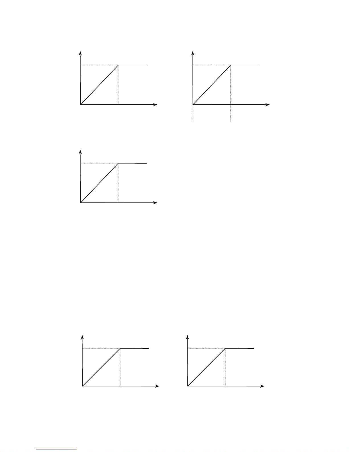
Fig. 5.3.1: Analog Control Source Diagrams
(
)
(
)
Frequency
F_max
0V
Frequency
F_max
4mA 20mA
Frequency
F_max
10V
H6 = 0: Voltage H6 = 2: Voltage + Current
[H6 = Voltage]
Freq. ref.
Freq. ref.
4 ~ 20mA
+ 0 ~ 10V
[H6 = Volt + Curr.]
Freq. ref.
H6 = 1: Current
[H6 = Current]
H8, Analog Input Gain, establishes the correct ratio between the analog input signal
and its maximum speed reference of the drive. For example, if the drive needs to
accept +5 VDC analog signal as its maximum speed reference instead of +10 VDC,
by setting H8 to 50% the drive will calculate its maximum analog input as
10 VDC x (0.5) = 5 VDC. This establishes a +5 VDC input signal as the maximum
speed reference. See Fig. 5.3.2.
Fig. 5.3.2: Analog Input Gain
Frequency
F_max
Frequency
F_max
0V
4mA
72
10V(20mA)
[H8 = 100%]
Freq. ref.
0V
4mA
5V(12mA)
[H8 = 50%]
Freq. ref.
Page 73
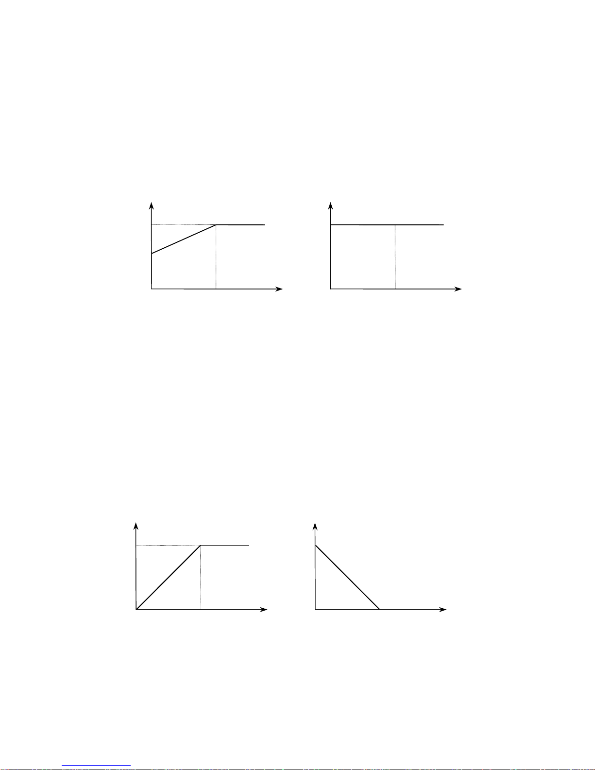
H8 is used to set the ratio between the maximum analog input signal and the
(
))
(
)
(
)
(
)
maximum frequency reference. H9, Analog Input Bias, establishes the ratio between
the minimum analog input signal and the minimum frequency reference. For
example, if H9 is set at 50% and the analog input signal is 0 VDC, then the drive will
calculate its minimum speed reference (maximum speed x H9) which becomes half
of the set maximum frequency.
Fig. 5.3.3: Analog Input Bias
Frequency
Fmax
Fmax/2
0V
4mA
10V(20mA)
[H9 = 50%]
Freq. ref.
Frequency
Fmax
0V
4mA
10V(20mA)
[H9 = 100%]
Freq. ref.
H10, Analog Input Direction, establishes the analog input versus frequency refer-
ence slope that is either a positive or negative slope. When set to 0: Direct the
analog command signal (0 ~ 10VDC or 4 ~ 20mA) represents an increasing or
positive slope. When set to 1: Inverse then the signal (0 ~ 10VDC or 4 ~ 20mA)
represents a decreasing or negative slope. See Fig. 5.3.4.
Fig. 5.3.4: Analog Reference Slope
Frequency
Fmax
0V
4mA
10V(20mA)
[H10 = Direct]
Freq. ref.
Frequency
Fmax
0V
4mA
10V(20mA)
[H10 = In-
[H10 = Invert]
verse]
Freq. ref.
73
Page 74
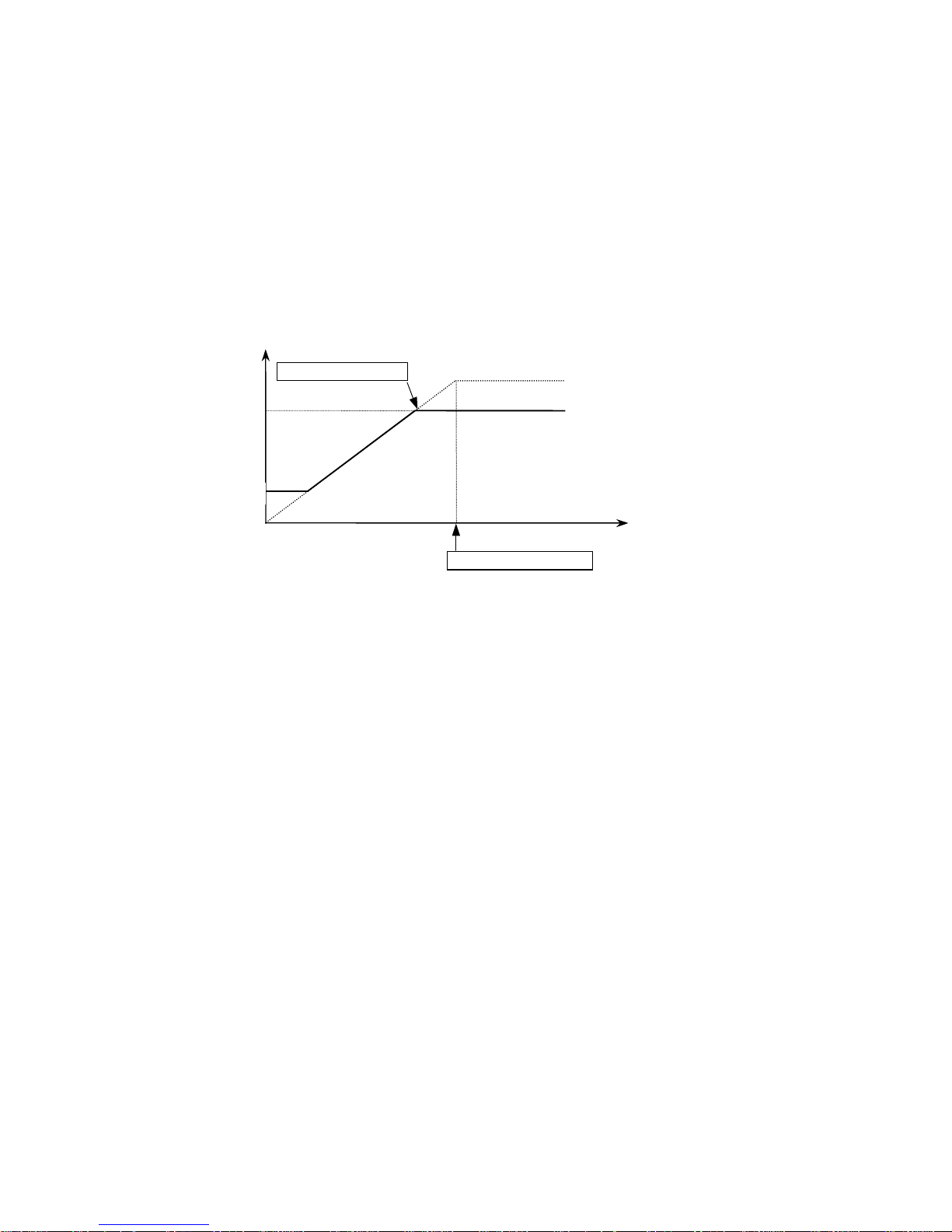
5.3.4 Maximum / Minimum Operating Frequency
H11: Maximum Operating Frequency
Range:0.0 - F9 Hz. (Factory Default: 60.0 Hz)
H12: Minimum Operating Frequency (Factory Default: 0.0 Hz)
Range:0.0 - F9 Hz.
The output frequency range of the drive is limited to the values set in H11 and H12.
See Fig. 5.3.5.
Fig. 5.3.5: Operational Maximum Frequency
Output Frequency
Limited Frequency
H11
50Hz
H12
10Hz
Command Frequency
Freq. ref.
74
Page 75
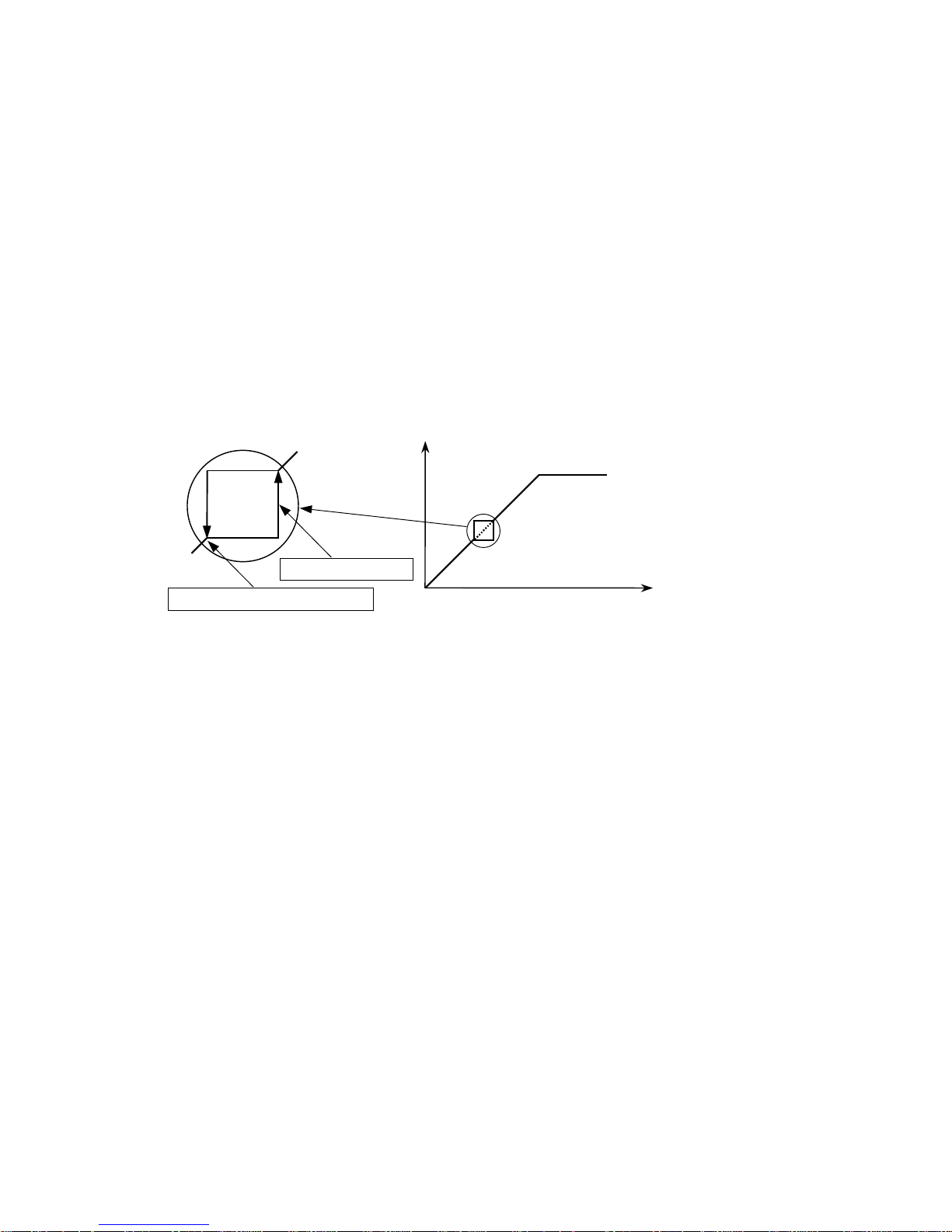
5.3.5 Frequency to Bypass
H13: Frequency to Bypass (Factory Default: 0.0 Hz)
Range:0.0 - F9 Hz.
H14: Frequency Bandwidth To Bypass (Factory Default: 0.0 Hz)
Range:0.0 - 30.0 Hz.
Undesirable resonance and vibration on the motor shaft of the hoist or crane could
occur within a certain frequency range due to the structure of the machine. This
frequency bypass function is used to lock that frequency band out of operation.
Most of the time, this phenomenon occurs only at a specific frequency. The jump
frequency also has its own bandwidth. This is a span of the particular bypass
frequency selected. See Fig. 5.3.6.
Fig. 5.3.6: Frequency Bypass
Output freq.
Bandwidth H14
Jump frequency H13
preset freq.
75
Page 76
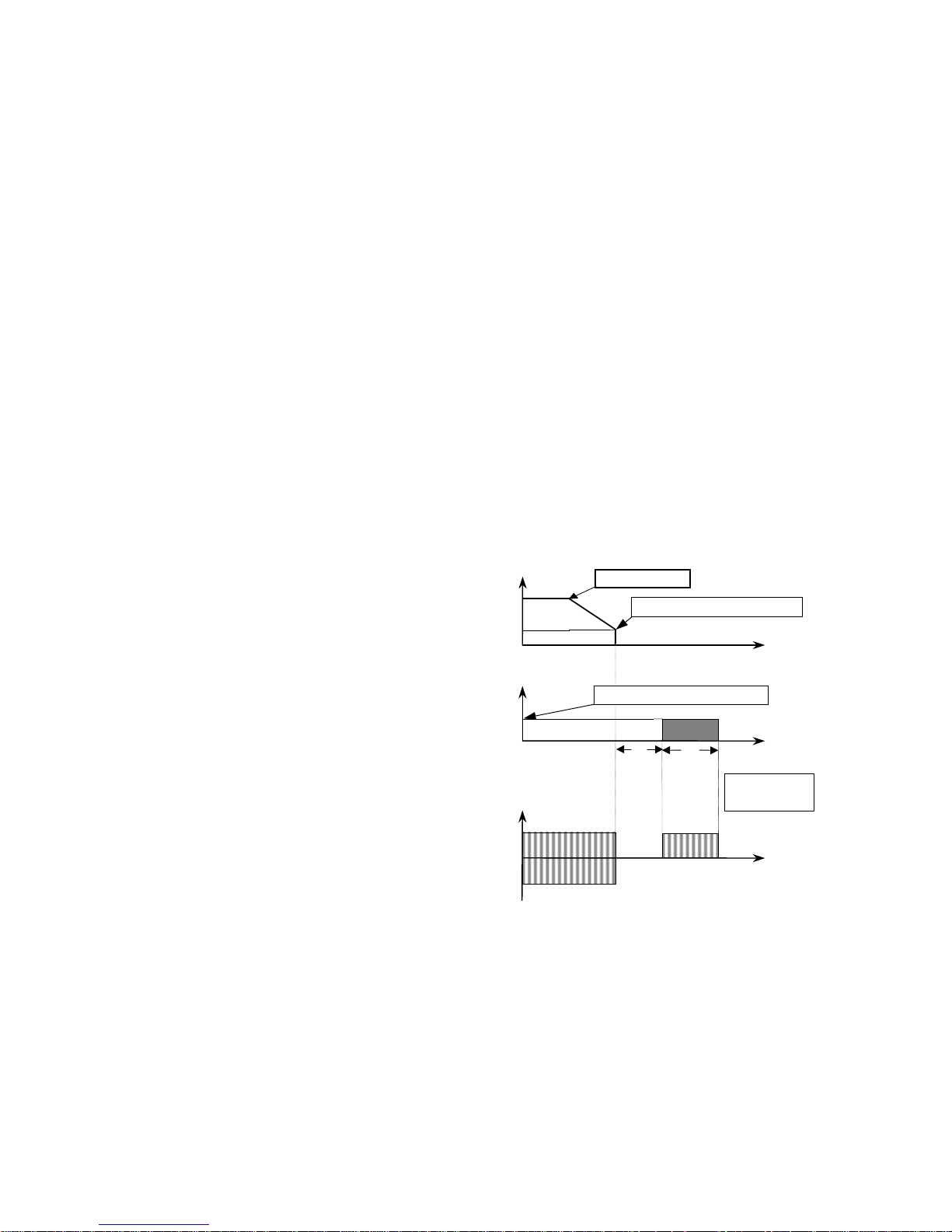
5.3.6 DC Braking
H15: DC Braking Frequency (Factory Default: 5.0 Hz.)
Range:0.0 - 20.0 Hz
H16: DC Braking V oltage (Factory Default: 5%)
Range:0 - 20 %
H17: DC Braking Block T ime (Factory Default: 0.5 sec.)
Range:0.0 - 5.0 sec.
H18: DC Braking T ime (Factory Default: 2.0 sec.)
Range:0.0 - 20.0 sec.
This function can be used to bring the hoist to a quick stop without the use of
Dynamic Braking Resistors. H15 sets the starting frequency where the DC Injection
begins. H17 is the time between the DC Injection command and the actual desired
moment of DC injection output. H18 is the total braking time.
H16 is the level of DC Injection Voltage Output (% of rated voltage). The DC
Injection Braking can be selected by selecting DC Brake in F21. This method can
also be used to build up magnetic flux in the hoist motor for smooth starting motion.
See Fig. 5.3.7.
Fig. 5.3.7: DC injection Braking
The hoist decelerates down to the DC
Braking Frequency level first before DC
Braking. Drive stops producing any Output
voltage for t1. Drive will produce the DC
braking voltage for t2.
Output freq.
Output volt.
2%
Output current
Stop signal
Stop Signal
DC braking volt.
t1 t2
DC braking freq.
time
time
t1=H17
t2=H18
time
76
Page 77

5.3.7 Motor Data
In order for the drive to operate the motor with slip compensation, the name plate
data of the motor must be programmed correctly. Without this data, the drive output
torque can be insufficient and could cause the motor to overheat in some instances.
H19: Slip Compensation (Factory Default: 0:Inactive)
Range:0: Inactive
1: Active
H19, Slip Compensation, is selected to compensate the motor for inherent slippage.
By selecting this function, the drive will hold a constant speed range by generating a
higher frequency output to the motor.
H20: Rated Slip of the Motor (Factory Default: 3.0 Hz)
Range:0.0 - 5.0 Hz.
H21: Rated Current of the Motor (FLA) (Factory Default: See Table 5.2.2)
Range:0.1 - 60.0 A
H22: No Load Current of the Motor (Factory Default: See Table 5.2.2)
Range:0.1 - 60.0 A
Refer to Section 3.3 for formulas to calculate these motor parameters.
77
Page 78
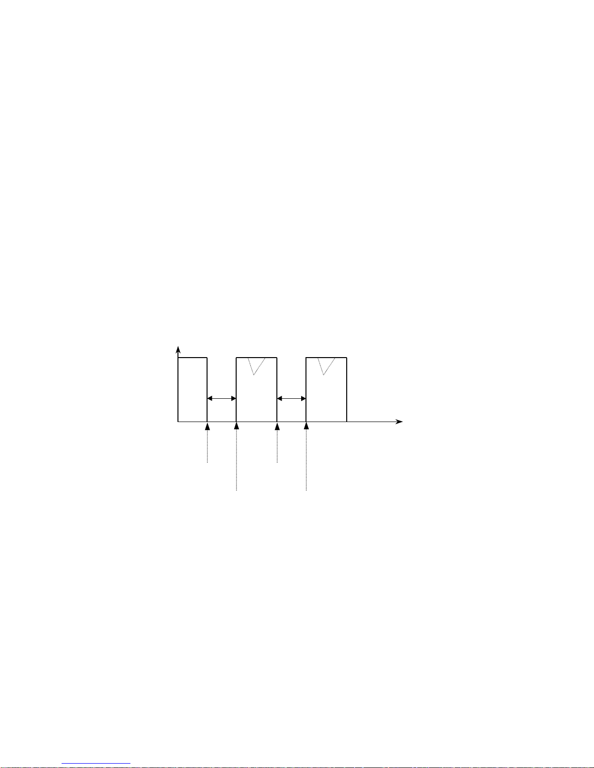
5.3.8 Auto Restart
H23:
Retry Number (Factory default: 0)
Range: 0 - 10 times
H24: Retry Time (Factory default: 0.5 sec.)
Range:0.0 - 10.0 sec.
H25: Retry Mode (Factory default: 0)
Range:0: Non-operation during L V fault and retry
1: Non-operation during LV fault
2: Non-operation during retry
3: Driving in all faults
These functions are used so the drive can reset itself automatically from all drive
faults except Low Voltage or BX fault. The operator can set the maximum number of
auto-restart trials through H23,Retry Number, and Retry Time (a waiting time before
the next restart attempt) through H24. The Auto-Restart works in conjunction with
the Speed Search Mode, see Section 5.3.11. See Fig. 5.3.8.
Fig. 5.3.8: Auto Restart Function
Output freq.[Hz]
First Fault
First Retry
tt
Second Fault
Second Retry
t : Retry time H24
time
78
Page 79

5.3.9 Stall Prevention
H26: Stall Prevention Mode Selection (Factory Default: 0:Disable)
Range:0: Disable
1: Stall prevention during acceleration
2: Stall prevention during steady speed
3: Stall prevention during acceleration and steady speed
4: Stall prevention during deceleration
5: Stall prevention during acceleration + deceleration
6: Stall prevention during deceleration + steady speed
7: Stall prevention during acceleration + deceleration + steady speed
H27: Stall Prevention Level (Factory Default Setting : 150%)
Range:30 - 150%
NOTE: DO NOT USE ST ALL PREVENTION ON HOIST MOTION.
GREA T CARE SHOULD BE EXERCISED WHEN SELECTING DECELERATION
(P ARAMETER VALUES 4 THROUGH 7) AS A STALL PREVENTION MODE WHEN
USING A DYNAMIC BRAKING RESISTOR.
These functions are used to prevent the traverse faults that occur due to load
fluctuation by reducing the inverter output frequency until the motor current level
decreases below H27, Stall Prevention Level. Once the motor current level satisfies
the value of H27, then the drive will increase its output frequency to its set point.
ACCELERATION
If the output current of the drive has reached the stall prevention level during drive
acceleration, the drive will stop accelerating until the current level is reduced below
H27 before it resumes acceleration to a set frequency command. See Fig. 5.3.9.
STEADY SPEED
If the output current of the drive has reached the stall prevention level during a
steady speed period, due to load fluctuation, the drive will then reduce its output
frequency until the output current level is reduced below H27. The drive will then
increase its output frequency to the set frequency command. See Fig. 5.3.10.
DECELERATION
If the DC BUS voltage reaches the Over Voltage fault level (790 VDC for the 460
VAC class, 390 VDC for the 230 VAC class) during deceleration, the drive will stop
further deceleration until DC Bus voltage drops below the fault level. See Fig.
5.3.11.
79
Page 80
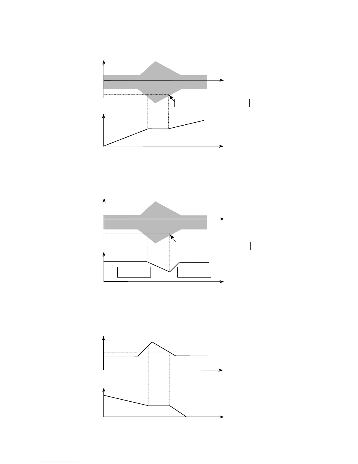
Fig. 5.3.9: Stall Prevention during Acceleration
Output current
180%
Stall prevention level H27
Output freq.
Fig. 5.3.10: Stall Prevention during Steady Speed
Output current
time
time
180%
Output freq.
Decel. Ramp Accel. Ramp
Stall prevention level H27
Fig. 5.3.11: Stall Prevention during Deceleration-230V Class
Output volt.
390V
380V
Output freq.
time
time
time
80
time
Page 81
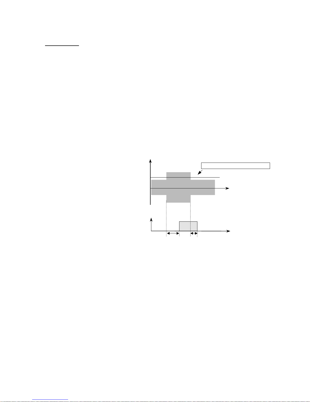
5.3.10 Drive and Motor Protections
OVERLOAD
H28:
Over Load Level (Factory Default: 150%)
Range:30 - 150%
H29: Over Load Time (Factory Default: 10.0 Sec.)
Range:0.1 - 30 sec.
This function is used to provide a motor overload warning. When the output current
of the drive has reached the value of H28, Oveload Level, the Multi-Function Output
terminal will be activated, if programmed. However, for an Overload Signal to occur,
H28 and H29, Overload Time, must be set to the desired trip value. As there is only
one Multi-Function Output available, there will be no brake control, therefore it is
advised this function NOT be used in hoist applications. See Fig. 5.3.12.
Fig. 5.3.12: Multi-Function Output response to Overload Parameter
Output current
Overload level H28
If the over load condition continues
for more than H29, an external
multifunction output terminal will be
turned on if F9 is set to Over Load.
time
B3 – B4
H29
ON
½ H29
time
81
Page 82
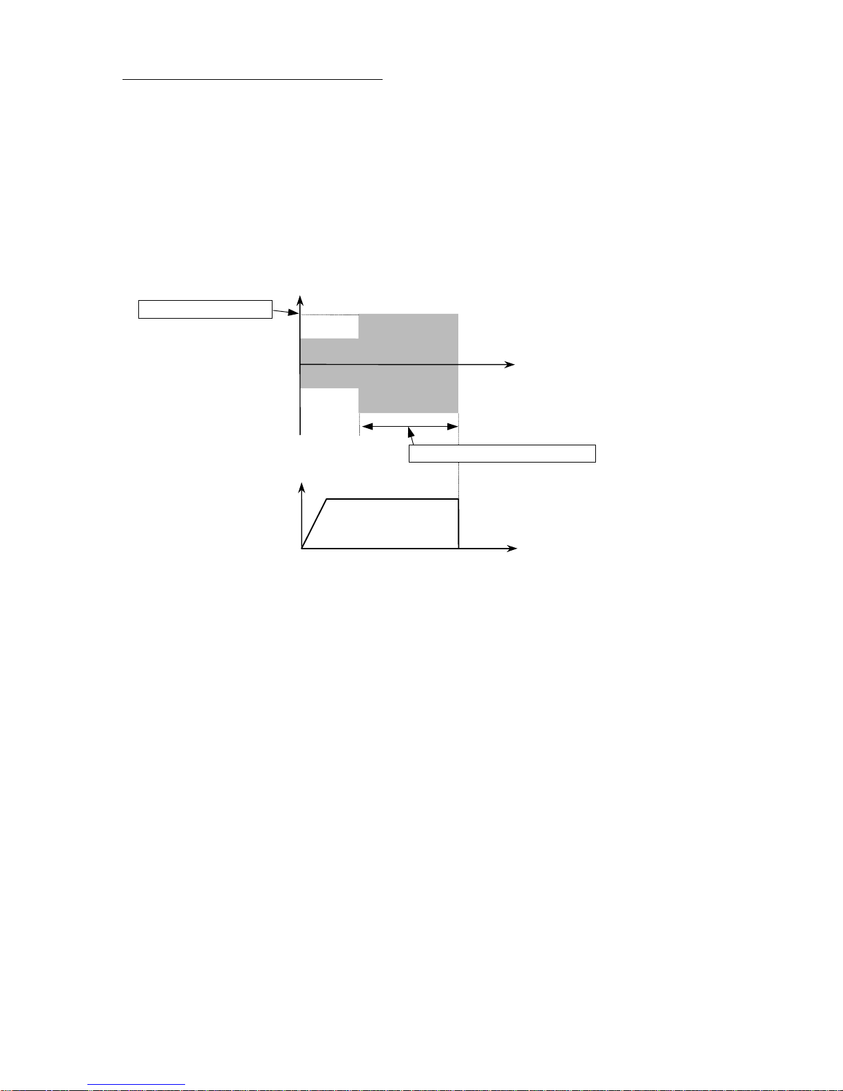
OVERCURRENT LIMIT TIME (OLt)
H30: Overcurrent Limit Time (Factory Default: 0.1 sec. Hoist
Range: 0.0 - 60.0 sec. 30.0 sec. Traverse)
When output current of the drive reaches 180% of drive rated output current for a
continuous time set in H30, Overcurrent Limit Time, an OLt Fault will occur and the
motor will stop. See Fig. 5.3.13.
Fig. 5.3.13: Overcurrent Limit Drive Response.
Output current
180 % of Rated Current
time
Overcurrent Limit Time, H30
Output Frequency
time
82
Page 83

ELECTRONIC THERMAL DETECTION (EtH)
H31: EtH Selection (Factory Default: 1: Active)
Range:0: Inactive
1: Active
H32: EtH Level (Factory Default: 150%)
Range:30 - 150%
H33: Motor T ype Selection (Factory Default: 0: General)
Range:0: General
1: Special
This function is used to compensate for excessive motor heat generated during
continuous low frequency operation. This is especially true if the capacity of the
hoist motor is lower than that of the inverter. To prevent the motor from overheating,
the EtH level must be set according to the provided formula.
EtH level (%) = K x (Motor rated current / Inverter rated current) x 100%
(K = 1.0 for 50Hz Input Frequency, K = 1.1 for 60 Hz Input Frequency)
Once the EtH level is found, then the motor type of the hoist must be determined.
There are two electronic thermal characteristics, one is a General, a standard AC
induction motor, the other is Special, for a motor containing a forced air blower.
Once the correct values are programmed, the drive will determine the EtH time for
either the General or Special motor.
83
Page 84
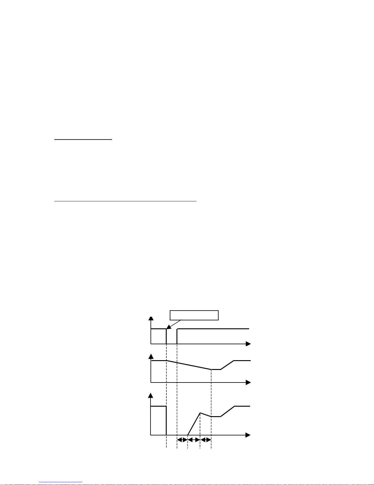
5.3.11 Instantaneous Power Failure and Speed Search
H34: IPF Restart (Factory Default: 0: Inactive Hoist
Range:0: Inactive 1: Active Traverse)
1: Active
H35: Speed Search Accel. Time (Factory Default: 2.0 sec.)
Range:0.1 - 10.0 sec.
H36: Speed Search Decel. Time (Factory Default: 2.0 sec.)
Range:0.1 - 10.0 sec.
H37: Speed Search Block Ti me (Factory Default: 0.0 sec.)
Range: 0.0 - 5.0 sec.
SPEED SEARCH
The Speed Search Mode is used when the drive needs to be restarted while a motor
is coasting. This function is especially important if the motor has a large load inertia.
IMPORTANT: Without speed search, restarting into a coasting motor can result in
over current in the IGBT’s.
INSTANTANEOUS POWER FAILURE (IPF)
This function is used to initiate the automatic restart mode after an IPF of over 15
msec. in duration. After the drive resets itself from an IPF it begins to search for the
current speed of the coasting motor following a time period equal to H37, Speed
Search Block Time. Once the drive determines the speed of the motor, it then
re-accelerates for a time equal to H35, Speed Search Accel. Time. The drive
decelerates for a time equal to H36, Speed Search Decel. Time, to allow the drive
output to match the decelerating motor speed. The drive then accelerates to the
previous set reference frequency. H35, H36, and H37 must be set, considering the
moment of inertia and the magnitude of torque demand of the load.
Fig. 5.3.14: IPF Function
Input Power
Motor Speed
Output Frequency
Input Power Loss
time
time
84
time
H37 H35 H36
Page 85
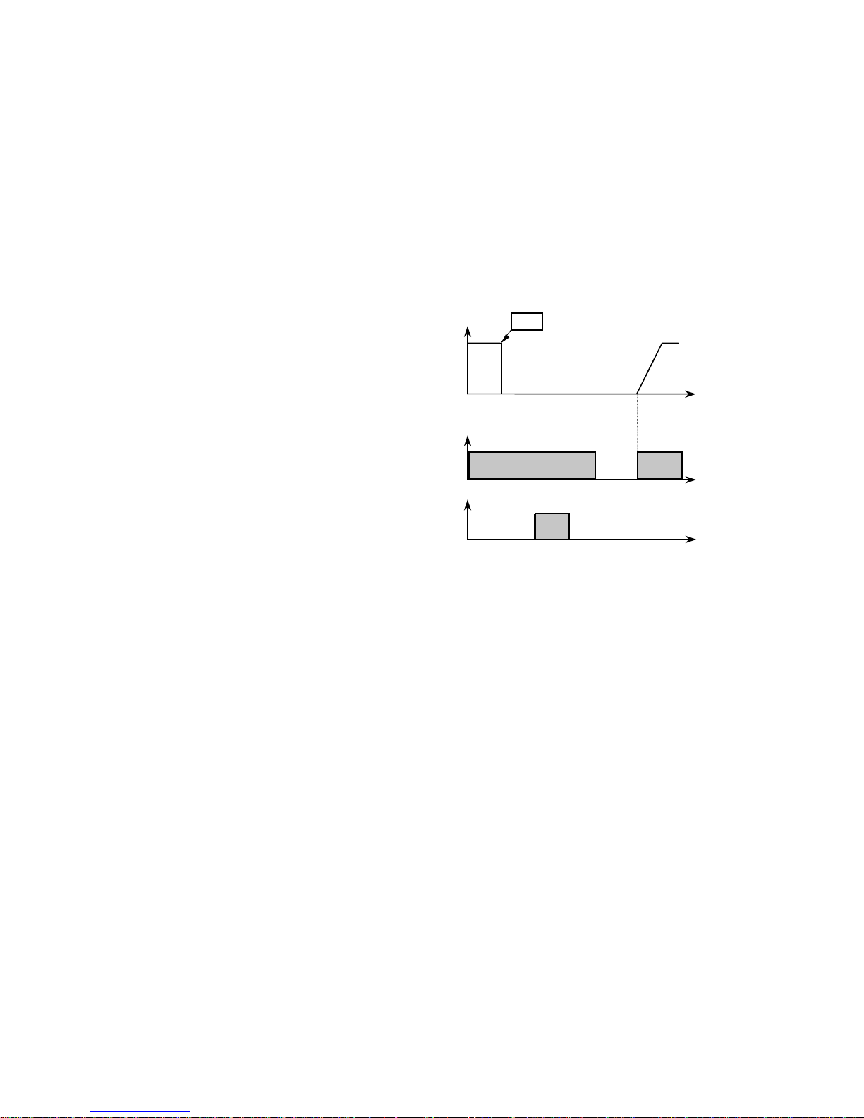
5.3.12 Restart After Reset
H38: Reset Restart (Factory Default: 0: Inactive)
Range:0: Inactive
1: Active
When Reset Restart is set to Active, the drive can be selected to automatically
initiate auto-restart mode after a manual reset. If this parameter is set to Inactive,
the drive must receive a RUN command after the manual reset.
Fig. 5.3.15: Reset Restart (H38) Inactive
When Reset Restart function is
inactive, F (UP/FORWARD) Pendant
buttons must be released, then
pressed again after a manual reset in
order to run the drive again.
F (UP/FORWARD)
Output Freq.[Hz]
F-G
Reset
Trip
Trip
No Effect
ON ON
ON
ON
Effect
ONON
time
85
Page 86
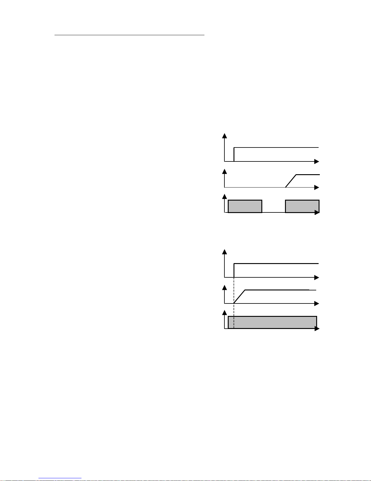
INPUT POWER DETECTED AUTO-RESTART
H39: Power On Start (Factory Default: 1: Active)
Range:0: Inactive
1: Active
With either the F (UP/FORWARD) input terminal or R (DOWN/REVERSE) input
terminal is energized and the input power is restored, the drive will initiate the autorestart automatically when H39, Power On Start, is set to Active. See Figs. 5.3.16
and 5.3.17.
Fig. 5.3.16: Power On Start Inactive
When Power On Start is set Inactive,
the drive will not run at the time of the
Power Up sequence. An external Run
Command must be given in order to
restart the drive.
Fig. 5.3.17: Power On Start Active
When Power On Start is set Active, the
drive will run at the time of the
Power Up sequence.
Input Power
Output Frequency
F (UP/FORWARD)
Input Power
Input Power ON
time
time
ON ON
time
Input Power ON
time
Output Frequency
F (UP/FORWARD)
ON
5.3.13 Carrier Frequency
H40: Carrier Frequency Selection (Factory Default: 3 kHz.)
Range:3 - 15 kHz.
This is the IGBT switching frequency. This function is generally used to prevent
harmonic resonance in machines and motors. If this PWM carrier frequency is set at
an appropriate level, both electronic noise and current leakage are reduced. If this
frequency is set too high, there can be an increase in audible noise. Generally, the
carrier frequency is set to a lower value in high ambient temperature environments.
86
time
time
Page 87
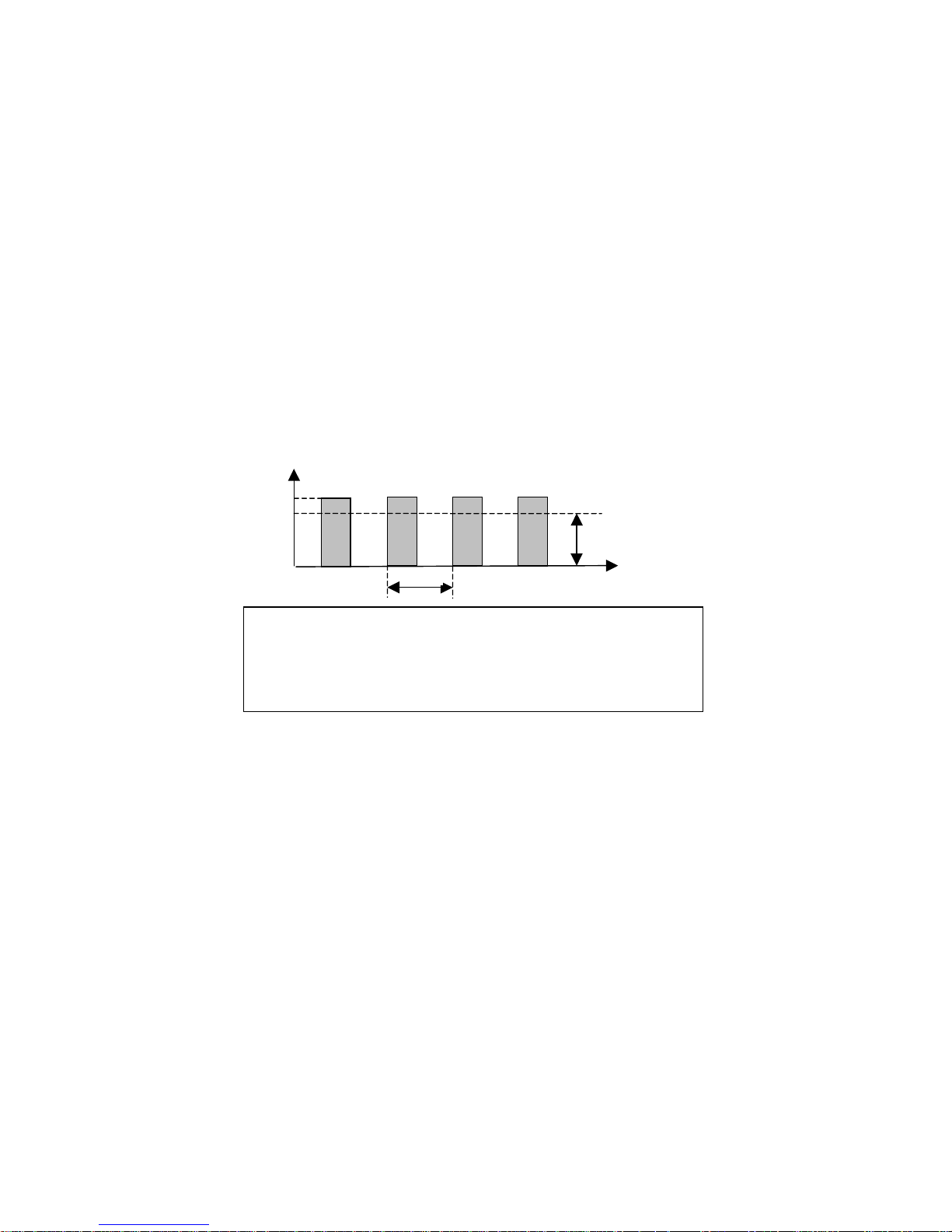
5.3.14 Multi-Meter Output for Current, Voltage, and Frequency
y
)
H46: Multi-Meter Mode Selection (Factory Default: 0:Frequency)
Range:0: Frequency
1: Output Voltage
2: Output Current
H47: Multi-meter Adjustment (Factory Default: 100%)
Range:0 - 120 %
The SV100 Frequency Drive has an FM terminal which can be programmed to
generate either a drive voltage, current or frequency output measured as a 0 ~
10VDC pulse signal. The measurement selection can be programmed in H46.
When a different ratio between FM output and actual drive voltage/current/frequency
measurement is required, the value of H47 can be set to meet the ratio requirement.
Fig. 5.3.18: Multi-Meter Output
Output Frequenc
10 V (peak
Average 0~10 V
FM
f
Frequency meter frequency (f) =
(Output frequency / Maximum frequency) x 1.8 kHz.
Duty (%) = (Output frequency / Maximum frequency) x 2/3
Frequency meter voltage =
(Output frequency / Maximum frequency) x 10V
time
5.3.15 Motor Phase Loss
H49:
Range: 0 - 5000 msec.
Phase Loss Check Time (Factory Default: 50 msec.)
The SV100 Frequency Drive has a Phase Loss Detection feature. If the drive
detects that there is not enough current output at one or more of the motor terminals
the drive will fault on Phase Loss (phf). Setting the value of H49, Phase Loss Check
Time, to zero will disable the phase loss detection feature. See Tables 4.1.1 and
4.1.2.
87
Page 88
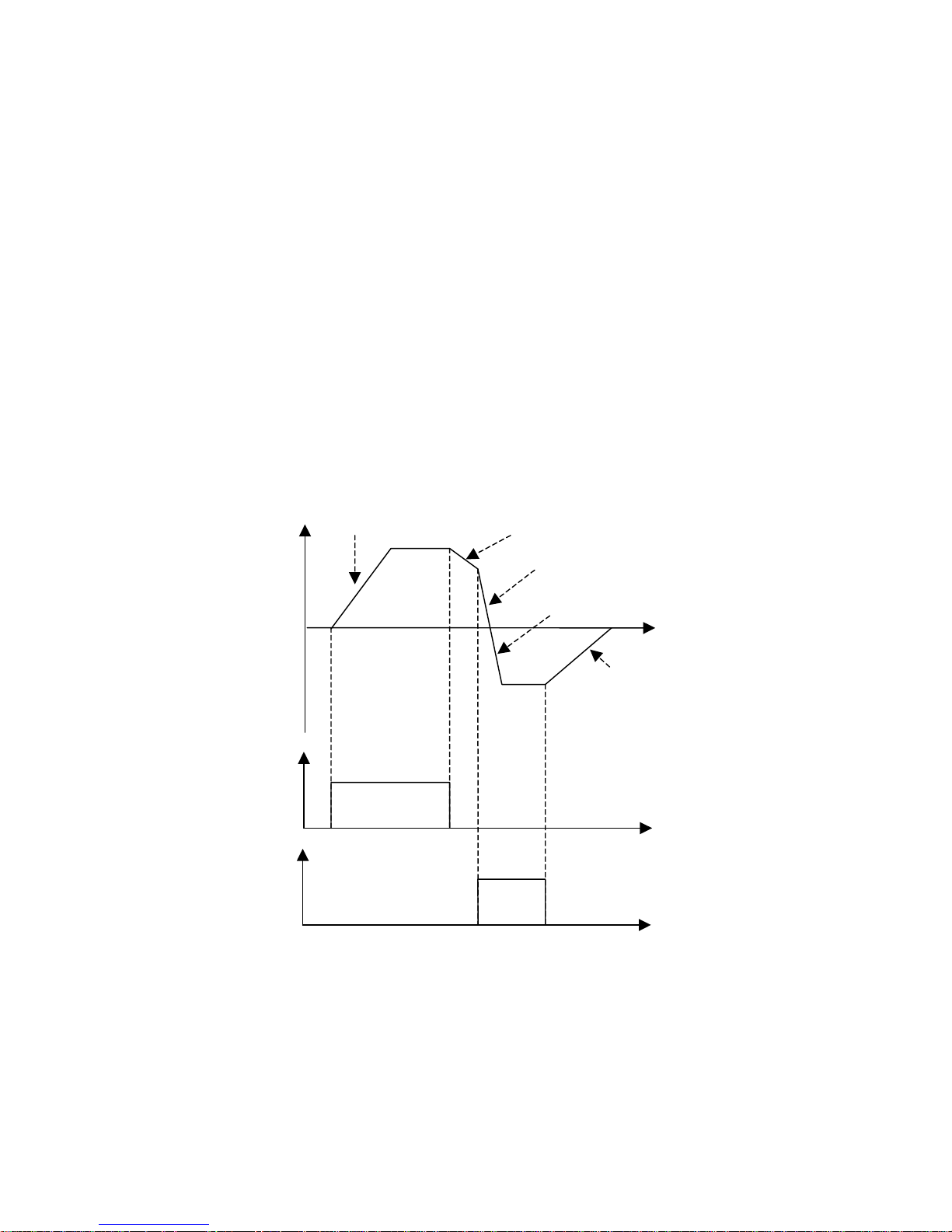
5.3.16 Reverse Plugging
H50: Reverse Plugging Enable (Factory Default: 0:Inactive)
Range:0: Inactive
1: Active
H51: Reverse Plugging Acceleration Time (Factory Default: 1.5 sec.)
Range:0 - 999 sec.
H52: Reverse Plugging Deceleration T ime(Factory Default: 1.5 sec.)
Range:0 - 999 sec.
Reverse plugging allows for a smooth and quick transition from one direction to the
opposite direction with minimal load swing.
NOTE: To be used for traverse applications only.
Motors may need to be oversized from standard motor size calculations by
approximately 50 % to be able to handle the extra current required to be able
to reverse plug motors with loads near equipment capacity.
Fig. 5.3.19: Reverse Plugging
Frequency
Direction A
Direction B
Normal Acceleration
Normal Deceleration
Reverse Plugging Deceleration
Reverse Plugging Acceleration
time
Normal Deceleration
time
time
88
Page 89

Chapter 6: Maintenance
Section 6.1: Maintenance
Section 6.2: Precautions
Section 6.3: Routine Inspection
Section 6.4: Visual Inspection
89
Page 90

6.1 Maintenance
SV100 Series can be influenced by temperature, humidity , and vibration. To avoid any
possible uncertainty, the drive must be installed and maintained properly by trained
personnel.
6.2 Precaution
Only certified personnel familiar with the equipment are permitted to install, operate
and maintain the drive.
Observe the Charge LED on the drive to be sure of complete power dissipation.
The output voltage of your SV100 drive can only be measured by a rectifier voltage
meter(such as RMS meter). Other instruments such as a digital meter will read an
incorrect value due to the high switching PWM frequency.
6.3 Routine Inspection
Check Input-Line Voltage to the drive for any fluctuation.
Check the Cooling Fan. If there is any abnormal noise, replace.
Check for any physical vibration to the drive.
Check the temperature for any overheating.
6.4 Visual Inspection
Any loose screws, nuts, or wires?
➝➝
➝ Tighten or replace.
➝➝
Any deposit of dust or foreign material in the AC Drive or Cooling Fan?
➝➝
➝ Clean off the dust or foreign material.
➝➝
Are any connectors disconnected from printed circuit boards?
➝➝
➝ Re-insert the connector.
➝➝
Inspect for corrosion.
➝➝
➝ Clean where possible or replace.
➝➝
90
Page 91
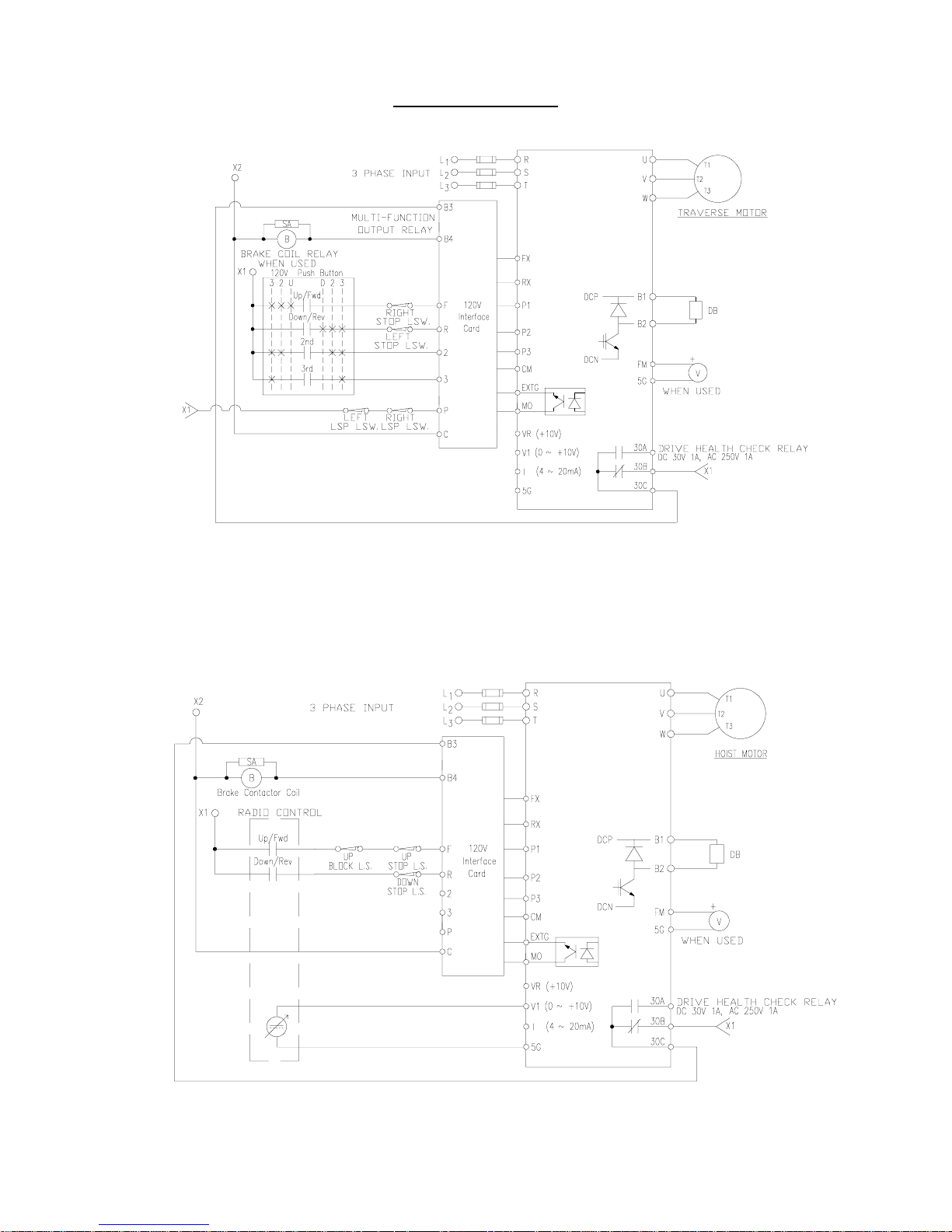
Appendix
Appendix Fig. 1: Sample Traverse Wiring Diagram
Traverse Wiring Diagram Example: Multi-Function Input F6 set for 7: Low Speed LS
Appendix Fig. 2: Sample Hoist Wiring Diagram with Analog Control
Hoist Wiring Diagram Example: Advanced Level H1 set for 1: Analog
91
Page 92
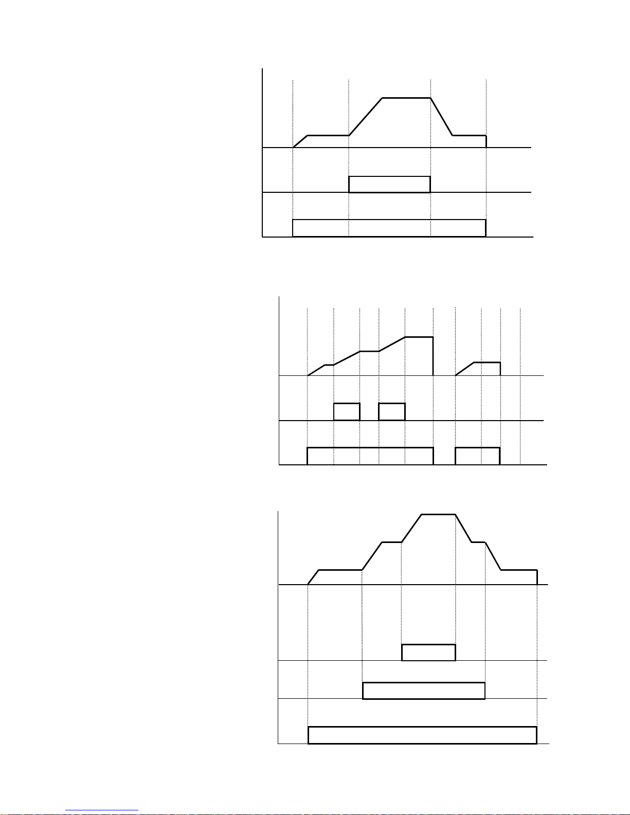
Appendix Fig. 3: 2 Speed Control
SPEED
2 – SPEED 2
F UP / FORWARD
Appendix Fig. 4: 2 Step Infinitely Variable Speed Control
3 – FREQUENCY INCREASING
F – UP / FORWARD
Appendix Fig. 5: 3 Speed Control
SPEED
SPEED
P2
F UP / FORWARD
92
P1
Page 93
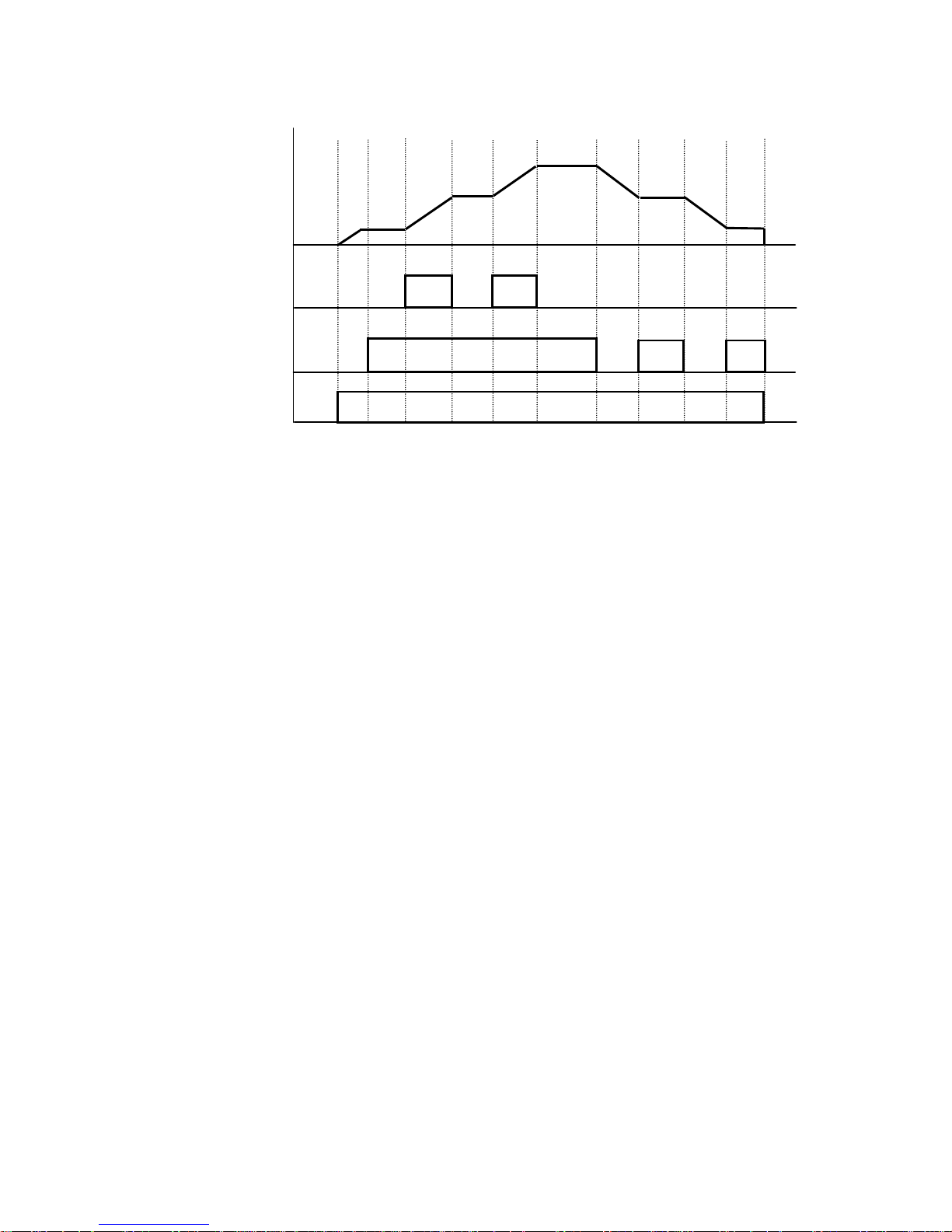
Appendix Fig. 5: 3 Step Infinitely Variable Speed Control
SPEED
3 – FREQ. INC.
2 - HOLD
F UP/FORWARD
93
Page 94

NOTES
94
Page 95

NOTES
95
Page 96
TM
™
414 W. BROADWAY AVE.
MUSKEGON, MI 49443-0769
Phone: 877 226-6278
Fax: 231 733-3223
WARRANTY
WARRANTY AND LIMITATION OF REMEDY AND LIABILITY
A. Seller warrants that its products and parts, when shipped,
and its work (including installation, construction and start-up),
when performed, will meet applicable specifications, will be of
good quality and will be free from defects in material and
workmanship. All claims for defective products or parts under
this warranty must be made in writing immediately upon
discovery and, in any event, within two (2) years (or as otherwise
provided) from shipment of the applicable item unless Seller
specifically assumes installation, construction or start-up
responsibility. All claims for defective products or parts when
Seller specifically assumes installation, construction or startup responsibility, and all claims for defective work must be made
in writing immediately upon discovery and, in any event, within
two (2) years (or as otherwise provided) from completion of
the applicable work by Seller, provided, however , all claims for
defective products and parts must be made in writing no later
than thirty (30) months after shipment. Defective items must
be held for Seller’s inspection and returned to the original f.o.b.
point upon request. THE FOREGOING IS EXPRESSLY IN
LIEU OF ALL OTHER WARRANTIES WHATSOEVER,
EXPRESS, IMPLIED AND STATUTORY, INCLUDING,
WITHOUT LIMITATION, THE IMPLIED WARRANTIES OF
MERCHANTABILITY AND FITNESS.
P.O. BOX 1000
FORREST CITY, AR 72335
Phone: 800 999-6318
Fax: 800 766-0223
B. Upon Buyer’s submission of a claim as provided above and
its substantiation, Seller shall, at its option, either (i) repair or
replace its product, part or work at either the original f.o.b.
point of delivery or at Seller’s authorized service station nearest
Buyer or (ii) refund an equitable portion of the purchase price.
C. This warranty is contingent upon Buyer’s proper maintenance
and care of Seller’s products, and does not extend to normal
wear and tear. Seller reserves the right to void warranty in
event of Buyer’s use of inappropriate materials in the course
of repair or maintenance, or if Seller’s products have been
dismantled prior to submission to Seller for warranty inspection.
D. The foregoing is Seller’s only obligation and Buyer’s
exclusive remedy for breach of warranty, and is Buyer’s
exclusive remedy hereunder by way of breach of contract, tort,
strict liability or otherwise. In no event shall Buyer be entitled
to or Seller liable for incidental or consequential damages. Any
action for breach of this warranty must be commenced within
two (2) years (or as otherwise provided) after the cause of
action has accrued.
February 2000 COPYRIGHT 2000 Columbus McKinnon Corporation 117463-1
96
 Loading...