

Crane Merchandising Systems Voce Media Series, Voce Media 605, Voce Media 607 Service Information
Page 1

SERVICE INFORMATION
M 138.0
MODELS AFFECTED: All Voce Media Date: 04/17/15
MODEL NUMBERS: 605 & 607
RE: Voce Media Card Reader Blank Bezel Installation
Reason: To provide instructions on removal of Voce Media Card Reader & Mag Head Assembly and installation of blue Card
Reader Blank Bezel in the field.
What’s needed: See list of parts required:
Order:
Description Part Number QTY
Card Reader Blank Bezel (blue) CR0023374 1
Blank Swipe Bracket CR0023375 1
Screw, Phil Pan #6 – 19 X .38 4747171 4
Installation Instructions M138.x 1
Tools Required:
Phillips screw driver T20 Torx Driver Painters Tape or an Assistant
M138.x Page 1 of 6 April 17, 2015
Page 2
SERVICE INFORMATION
Voce Kit Installation Instructions:
1. Remove power to the vender.
2. Unplug the Coin Mechanism.
3. Loosen the 2 Phillips screws securing the LED Driver Board Cover.
a.
4. Remove the LED Driver Board Cover.
a.
5. Unplug all harnesses from the LED Driver Board.
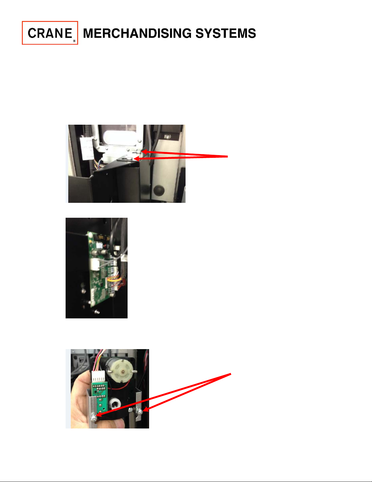
6. Loosen the 2 Phillips screws securing the Coin Reject Motor Assembly.
a.
M138.x Page 2 of 6 April 17, 2015
Page 3

SERVICE INFORMATION
7. Remove the Coin Reject Motor Assembly from the Monetary Door Assembly and let hang. Be careful
not to damage harnessing or connectors. See picture 6.a.
8. Loosen the 3 Phillips screws securing the Monetary Door Assembly to the Main Door.
a.
9. Carefully remove the Monetary Door Assembly from the Main Door.
M138.x Page 3 of 6 April 17, 2015
Page 4

SERVICE INFORMATION
10. Unplug the Card Reader & Mag Head Assembly.
a.
11. Remove the 2 T20 Torx Screws securing the Card Reader & Mag Head Assembly to the Main Door.
One at the top of the Assembly and one at the bottom of the assembly.
a.
12. Remove the Card Reader & Mag Head Assembly from the front of the vender.
M138.x Page 4 of 6 April 17, 2015
Page 5

SERVICE INFORMATION
13. Position the Blue Card Reader Blank Bezel in place from the front of the door.
a.
14. Using the 4 screws and Blank Swipe Bracket provided with kit secure by following steps.
Caution: Do not overtighten screws in the Card Reader Blank Bezel.
a. Install the Top Screw in position and lightly tighten.
b. Install the Bottom Screw in position and lightly tighten.
c. Install bracket in position and secure with Middle Top Screw and lightly tighten.
d. Install bracket Middle Bottom Screw and lightly tighten.
1. Note: you will need someone to hold it in place while you secure it or you will need to
tape it in place while you secure it.
a
c
d
b
M138.x Page 5 of 6 April 17, 2015
Page 6

SERVICE INFORMATION
15. Close main Door and inspect part. If Card Reader Blank Bezel is overtightened it will appear warped.
Loosen screws as needed to allow part to flatten out.
a.
16. Install the Monetary Door Assembly on the Main Door and secure by tightening the 3 screws loosened
in step 8.
17. Install the Coin Reject Motor Assembly and secure by tightening the 2 screws loosened in step 6.
18. Plug the harnessing in the LED Driver Board that were unplugged in step 5.
19. Place LED Driver Board Cover back in position and secure by tightening the 2 screws loosened in step
3.
20. Turn power on to vender. Test for proper operation.
M138.x Page 6 of 6 April 17, 2015
 Loading...