

Page 1
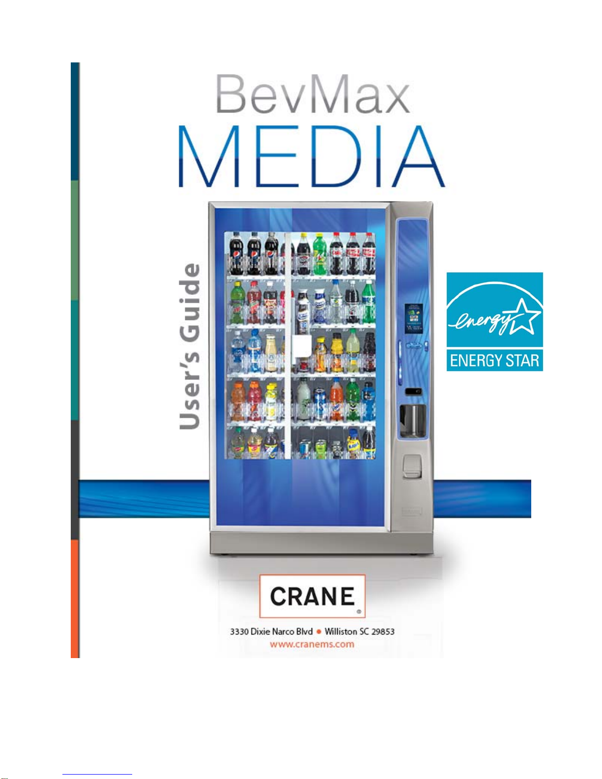
Tier 3
English 80390486
0 of 130
Page 2

Table of Contents
GENERAL INFORMATION .................................................................................. 3
Vender Safety Precautions .................................................................................................. 3
Product Identification ........................................................................................................... 3
CE Mark & IIA Declaration ................................................................................................... 3
Physical Characteristics ...................................................................................................... 3
INSTALLATION & SETUP ............................................................................ 3 - 10
Receiving Inspection ........................................................................................................... 3
Unpacking the Vender ................................................................................................... 3 - 4
Electrical Requirements ....................................................................................................... 4
Power Supply & Grounding Requirements .................................................................... 4 - 5
Installation & Setup Instructions .................................................................................... 5 - 6
Placing the Vender on Location ...................................................................................... 6 -7
Acceptable Ambient Operating Temperature Range .......................................................... 7
Storage Conditions .............................................................................................................. 7
Leveling the Vender ............................................................................................................. 7
Clearance Requirements ..................................................................................................... 7
Installing Labels & Product ID Cards ................................................................................... 7
Coin Changers and Other Accessories ......................................................................... 7 - 8
Set Temperature Control ..................................................................................................... 8
Loading the Vender ............................................................................................................. 8
Loading the Coin Changer ................................................................................................... 8
Power AC Distribution Box .................................................................................................. 8
Vending Machine Controllers ........................................................................................ 8 - 9
Touch Screen Display/Keypad ............................................................................................ 9
Refrigeration System ........................................................................................................... 9
Shelf Assembly .................................................................................................................... 9
Double Gate Assembly ........................................................................................................ 9
Slide / Pusher Assembly ...................................................................................................... 9
Deliver (Picker) Cup Assembly ............................................................................................ 9
Refrigeration Deck Clamp Assembly ................................................................................... 9
Belt Tensioning Adjustment Components ................................................................... 9 – 10
The Pill ............................................................................................................................... 10
Pill Lighting ........................................................................................................................ 10
PROGRAMMING ........................................................................................ 10 - 97
General .............................................................................................................................. 10
Move Thru the Menu Icons ................................................................................................ 10
Display of Products & Nutritional Information ............................................................ 10 - 11
Normal Operation Messages ............................................................................................. 11
Initial Programming ............................................................................................................ 11
Quick Reference Menu Items .................................................................................... 12 - 13
Data Recall ................................................................................................................14 – 21
Diagnostics ................................................................................................................21 – 32
Test ............................................................................................................................33 – 37
Price ...........................................................................................................................37 – 38
Product Configuration ................................................................................................38 – 44
Special Vend Modes ..................................................................................................45 – 54
Monetary ....................................................................................................................54 – 58
System Settings .........................................................................................................59 – 70
Security Codes .......................................................................................................... 71 - 77
Timed Events ............................................................................................................. 77 - 84
Telemetry ................................................................................................................... 84 - 92
Machine Configuration ............................................................................................... 93 - 97
CONTROL BOARD .................................................................................. 98 - 100
LED Driver Controller Connections ................................................................................... 98
I/O Controller Connections ................................................................................................ 99
Atlas Controller Connections ........................................................................................... 100
1 of 130
Page 3
TROUBLESHOOTING ........................................................................... 101 – 120
–
XY Issues ............................................................................................................... 101 - 103
XY Not Working Flow Chart ............................................................................................. 104
Picker Motor Failure Flow Chart ...................................................................................... 105
X Motor Failure Flow Chart .............................................................................................. 106
Y Motor Failure Flow Chart .............................................................................................. 107
XY Slams to Top/Right or Left Flow Chart ...................................................................... 108
Picker Cup Not Working Flow Chart ................................................................................ 109
Picker Cup at Wrong Location Y Axis Flow Chart ........................................................... 110
Picker Cup at Wrong Location X Axis Flow Chart ........................................................... 111
Delivery Port Door Flow Chart ......................................................................................... 112
Coin Acceptance.............................................................................................................. 113
Bill Acceptors ................................................................................................................... 113
I/O Control Board ............................................................................................................. 113
All Coins Rejected Flow Chart ......................................................................................... 114
All Bills Rejected Flow Chart ........................................................................................... 115
Incorrect Change Dispensed Flow Chart ........................................................................ 116
Selection Will Not Vend Flow Chart ................................................................................. 117
Ice / Frost on Evaporator Flow Chart............................................................................... 118
Condensate on Outside of Product Door Flow Chart ...................................................... 118
Compressor Will Not Stop Flow Chart ............................................................................. 118
Compressor Will Not Start Flow Chart ............................................................................ 119
Machine Not Cooling Flow Chart ..................................................................................... 120
MAJOR COMPONENT DESCRIPTION ........................................................... 121
AC Distribution Box ......................................................................................................... 121
Service door Switches ..................................................................................................... 121
GENERAL MAINTENANCE .................................................................... 121 - 123
Power ............................................................................................................................... 121
Cleaning ................................................................................................................. 122 - 123
ELECTRICAL DIAGRAMS & SCHEMATICS ........................................ 124 – 127
Block Diagram Domestic ................................................................................................. 124
Block Diagram Export ...................................................................................................... 125
Compressor Parts Diagram - Domestic ........................................................................... 126
Compressor Parts Diagram - Export ............................................................................... 127
SHIPPING BRACKET REMOVAL ................................................................... 128
High Voltage Warning / Electrical
Warning Danger electricity, electric
shock.
Hazard Warning: Beware of moving machinery
Entanglement hazard. Keep hands, loose clothing,
and long hair away from moving parts.
A Gener ic Warning.
CAUTION: This machine is designed for indoor
usage only. Any other usage will void the
Manufacturer’s Warranty.
CAUTION: The electronic system components in this
machine utilize static sensitive components. Precautions
for handling sensitive devices should be observed when
handling these items.
2 of 130
Page 4
VENDER SAFETY PRECAUTIONS
Please read this manual in its entirety. This service
information is intended for use by a qualified service
technician who is familiar with proper and safe
procedures to be followed when repairing, replacing or
adjusting any Crane Merchandising Systems vender
components. All repairs should be performed by a
qualified service technician who is equipped with the
proper tools and replacement components, using
genuine Crane Merchandising Systems factory parts.
The appliance is not to be used by persons (including
children) with reduced physical, sensory or mental
capabilities, or lack of experience and knowledge,
unless they have been given supervision or
instruction. Children must be supervised not to play
with the appliance.
REPAIRS AND/OR SERVICING
ATTEMPTED BY UNQUALIFIED
PERSONS CAN RESULT IN
HAZARDS DEVELOPING DUE TO
IMPROPER ASSEMBLY OR
ADJUSTMENTS WHILE
PERFORMING SUCH REPAIRS.
PERSONS NOT HAVING A PROPER
BACKGROUND MAY SUBJECT
THEMSELVES TO THE RISK OF
INJURY OR ELECTRICAL SHOCK
WHICH CAN BE SERIOUS OR EVEN
FATAL.
edge of the product refrigerated area visible through
the glass door.
CE Mark & IIA Declaration:
An updated CE Mark or IIA Declaration document can
be provided upon request: If needed please contact
Technical Support Manager in Williston, SC. Phone:
1- 803-266-5001 or email bstaubs@cranems.com .
PHYSICAL CHARACTERISTICS
DN5800-6
DN5800-E6
HEIGHT
WIDTH
DEPTH
CABINET
DEPTH
WITH
SERVICE
DOOR
SHIPPING
WEIGHT
Noise
Level
Glass Door width = 37.5” (952.5 mm) 5800’s.
Glass Door width = 28.1” (713.74 mm) 3800’s.
Glass Door height = 68” (1727.2 mm) both.
73” (1854.2 mm) 73” (1854.2 mm)
47” (1193.8 mm) 40” (1016 mm)
32.05”
(814.07 mm)
33.5”
(850.9 mm)
710 lbs.
(322.05kg)
Operates at < 70db.
DN3800-6
DN3800-E6
32.05”
(814.07 mm)
33.5”
(850.9 mm)
648 lbs.
(293.93kg)
PRODUCT IDENTIFICATION
First production of BevMax 6 5800-6/3800-6 Domestic
and BevMax 6 5800-E6/3800-E6 Export Venders was
March/April 2013. The production date of Crane
Merchandising Systems products is determined by the
date code incorporated in the serial number.
The vender serial number takes the form xxxx-yyyy
zz. The first 4 digits (xxxx) identify the specific
vender. The next 4 digits (yyyy) identify the
manufacturing run that the vender was built in. The
last two alpha characters (zz) identify the quarter and
the year the vender was built. The first alpha
character identifies the quarter as follows:
The second alpha character identifies the year:
H = 2009 L = 2013
I = 2010 M = 2014
J = 2011 N = 2015
K = 2012 O = 2016
The Serial Number decals are located on the top left
corner of the back of the vender and on the left front
A= 1
B= 2
C= 3
D= 4
st
Quarter
nd
Quarter
rd
Quarter
th
Quarter
RECEIVING INSPECTION
DO NOT STORE THE VENDER OUTSIDE.
Upon receipt, inspect the vender for any shipping
damage. Note any damage on the bill of lading and
report any damage to the delivering carrier and follow
their instructions. Although the terms of sale are FOB
shipping point, which requires the consignee to
originate shipping damage claims, Crane
Merchandising Systems will gladly help if you must file
a claim.
UNPACKING THE VENDER
Remove the stretch wrap, fiberboard edge protectors
and corrugated front protector from the outside of
vender.
Do not store the vender with stretch
wrap on. Stretch wrap could bond to
the vender’s surface, which could
damage the finish.
Remove the shipping boards from the bottom of the
vender. The shipping boards are attached by the
leveling legs. To avoid unnecessary damage to the
leveling legs or base, remove the shipping boards by
using a 1-1/2 inch or 38mm socket type wrench to
unscrew the leveling legs. Be sure to replace the legs
3 of 130
Page 5
after removing the shipping boards. Once the skid
boards are removed there is 3” (76.2 mm) from base
flange to the floor with the leveling legs screwed all
the way in.
Once the vender is unpacked, check the “B” Tray area
for any additional parts, price/product labels,
service/operation manual or other information
concerning factory-equipped accessories such as coin
mechanism and validator.
It is recommended the vender be vend tested before
shipping to the location. In programming see ”Test
Mode”, # 9 “Test Vend” to perform test vends.
Note: Remove tape from ends of top
lamp in the top lamp assembly after
placing the Vender on location, but
before plugging the Vender in to an AC
power supply.
WARNING: TO AVOID THE
POSSIBILITY OF A FIRE
HAZARD, DO NOT STORE
ANYTHING OR ALLOW
DEBRIS OF ANY KIND TO
ACCUMULATE IN THE
BOTTOM OF THE SERVICE
AREA, IN AND AROUND THE
REFRIGERATION
COMPARTMENT OF THE
CABINET, OR IN FRONT OF
THE EVAPORATOR AND
CONDENSER COILS.
WARNING: ENSURE THAT
POWER IS DISCONNECTED
FROM THE VENDER BEFORE
INSPECTING OR REPLACING
THE LAMPS, OTHER
ELECTRICAL COMPONENTS,
OR WORKING WITH OR
ADJUSTING THE VENDING
MECHANISM. FAILURE TO
COMPLY WITH THESE
INSTRUCTIONS MAY
SUBJECT THE USER TO THE
RISK OF ELECTRICAL
SHOCK OR MECHANICAL
INJURY, WHICH CAN BE
SERIOUS OR FATAL.
ELECTRICAL POWER NEEDED
Refer to the cabinet serial number plate to determine
the correct voltage and frequency for the machine. In
the US and Canada this is 120Vac, 60Hz, 1P. In
Europe, Australia, and other export countries, this is
220/230/240Vac, 50Hz, 1P depending upon your
country voltage. The serial plate also specifies the
ampere rating of the machine. This machine must be
plugged into a properly rated receptacle with its own
circuit protection (fuse or circuit breaker).
Equipment Nominal Power Requirements
120V / 10.2 A = *1224W (1.224kw)
220V / 5.8 A = *1276W (1.276kw)
240V / 5.8 A = *1392W (1.392kw)
*Note: Watts = V X A
DO NOT USE AN EXTENSION CORD.
POWER SUPPLY CORD and GROUNDING
REQUIREMENTS
In accordance with the National Electrical Code and
Underwriters Laboratories Inc., domestic vending
machines are equipped with a three-wire power
supply cord and Ground Fault Circuit Interrupter
(GFCI). The GFCI device is provided as part of the
power supply cord and is either incorporated directly
into the plug or mounted on the cord adjacent to the
plug.
WARNING
• The GFCI protects against current
leakage caused by ground faults.
The GFCI is not designed to protect
against over current or short
circuits.
• DO NOT use the TEST and RESET
buttons on the GFCI as an ON/OFF
switch.
• The vending machine supply cord
MUST be plugged directly into a
properly grounded, 3 wire
receptacle that is properly
protected by a fuse or circuit
breaker. If the receptacle will not
accept the power cord plug, it must
be replaced with a properly
grounded, 3 wire receptacle in
accordance with the National
Electrical Code and Local Codes
and Ordinances. The work should
be done by a qualified electrician.
DO NOT USE A 3 WIRE TO 2
WIRE ADAPTOR
4 of 130
Page 6

DO NOT REMOVE THE GROUND
PIN ON THE PLUG OR IN ANY WAY
BYPASS, MODIFY, DEFEAT, OR
DESTROY THE GROUNDING
SYSTEM OF THE VENDING
MACHINE
• DO NOT USE WITH AN EXTENSION CORD.
• DO NOT REMOVE THE WARNING TAG
ATTACHED TO THE POWER SUPPLY CORD.
• The GFCI must be tested frequently and before
each use in accordance with the instructions
provided on the GFCI device. IF THE GFCI
DOES NOT PASS THE TEST, DO NOT USE
THE MACHINE. Unplug the supply cord from the
receptacle and call the Crane Merchandising
Systems Technical Support Group for assistance
at 1-803-266-5001.
The BevMax 6 is supplied with a service cord for the
country of use and is terminated in a grounding type
plug. The wall receptacle for this machine must be
properly polarized, grounded, and of the correct
voltage. Note: Operating the machine from a source
of low voltage will VOID YOUR WARRANTY. Each
machine should have its own 15 Amp electrical circuit
and that circuit should be protected with a circuit
breaker or fuse conforming to local regulations.
1. Voltage Check – Place the leads of a
voltmeter across the LINE (LIVE) and
NEUTRAL terminals of the wall receptacle.
The volt meter should indicate 110-130 volts
ac for 120 volt, 60 Hz locations, or 220-240
volts ac for 230 volt, 50 Hz locations.
2. Polarity Check - Place the leads of a
voltmeter across the LINE (LIVE) and
GROUND terminals of the wall receptacle.
The volt meter should indicate 110-130 volts
ac for 120 volt, 60 Hz locations, or 220-240
volts ac for 230 volt, 50 Hz locations.
3. Noise Potential Check - Place the leads of a
voltmeter across the NEUTRAL and
GROUND terminals of the wall receptacle.
The volt meter should indicate 0 volts ac. A
measurement greater than 1.5-2.0 volts ac
could result in problems for the machines
electronic circuitry caused by electrical noise.
It is recommended that the machine be located so that
the GFCI device will be accessible after the machine
is installed. After installation, visually inspect the
GFCI and power supply cord to be sure it is not
crushed, pinched, or stretched.
Protect the power supply cord during transportation
and use. Periodically inspect the power supply cord
for damage. If the cord or plug is worn or damaged, it
must be replaced with a power supply cord of the
same type, size and specification as originally
provided with the machine. DO NOT USE THE
VENDING MACHINE UNTIL THE WORN OR
DAMAGED CORD IS REPLACED.
FAILURE TO COMPLY WITH
THESE INSTRUCTIONS MAY
SUBJECT THE USER TO THE RISK
OF INJURY OR ELECTRICAL
SHOCK WHICH CAN BE SERIOUS
OR FATAL. PERIODICALLY
INSPECT THE POWER SUPPLY
CORD FOR DAMAGE. IF THE
CORD BECOMES DAMAGED IT
MUST BE REPLACED WITH THE
SAME SIZE AND TYPE CORD.
CONTACT CRANE
MERCHANDISING SYSTEMS FOR
ASSISTANCE.
INSTALLATION AND SETUP
INSTRUCTIONS
ELECTRONIC LOCK
The electronic lock provided in the vender consists of
a door mounted, motor driven 2 point latching system,
cabinet mounted latch and strike system, an infrared
controlled CPU, and a remote control key (FOB). The
design is modular and allows for easy field service.
The electronic remote key (FOB) features a rolling
code system which cannot be decoded if it is lost or
stolen. After the vender has been unlocked, a new
key can be programmed into it any number of times.
If a key is lost or stolen, it is recommended you
change the lock code in the field as soon as possible.
Changing the lock code requires a new key and
pressing the PROGRAM button on the lock inside the
vender. The lock does not need to be changed for rekeying.
Important: For security reasons all Electronic
Door Lock Venders are shipped less
keys. Customers will need to contact
the Electronic Door Lock
manufacturer to order keys.
A power bypass connector, located in the product
delivery port, allows auxiliary power to be applied via
a battery pack to the electronic lock in the event that
power is not available or there has been a failure of
the internal power supply. In the event of an
emergency, battery power is applied to the connector
and the door can be opened and closed using the
FOB.
The electronics uses an infrared transmission system,
which functions similar to a television remote control.
The transmission signal is line-of-sight, which requires
you to aim the remote at a specific place at close
range to prevent the accidental opening of several
venders at the same time.
5 of 130
Page 7

TO OPEN THE ELECTRONIC DOOR LOCK:
1. Plug the vender into a properly powered
outlet.
2. Hold the key FOB 0 to 3” (76.2 mm) in front of
the Delivery Port Door and press the button
on the key FOB.
Note: The wide end of the FOB should face
the door.
3. The lock will begin releasing the door. The
display will indicate OPENED. After the motor
has stopped running, you can pull the door
open.
TO CLOSE THE ELECTRONIC DOOR LOCK:
CAUTION: DO NOT SLAM THE DOOR CLOSED.
Slamming the door closed can damage the electronic
locking device.
1. Push the door to the cabinet until the lock
motor starts. The display will indicate:
CLOSED
2. Continue to push the door for approximately 2
to 3 seconds after the lock motor starts. The
lock will pull the door closed tightly.
3. When the lock motor stops the door will be
locked. Before leaving the vender, ensure
that the door is locked.
The electronic door lock assembly is supplied by
TriTeq Lock and Security. Crane Merchandising
Systems does not carry parts for the TriTeq Electronic
Door Lock. For parts and assistance, please contact:
TriTeq
701 Gullo
Elk Grove Village, IL 60007
Tel: 847-640-7002
Fax: 847-640-7008
Email: triteqlock.com
MANUAL LOCK
Open the service door on the right side using the key
provided in the coin return cup, or if shipped with a
locking clip, remove the clip and install the lock.
Ensure there is no power to the AC Distribution Box.
On venders with a main power switch on the AC
Distribution Box the switch needs to be in the OFF
position. On venders with a main power quick
disconnect plug on the AC Distribution Box the quick
disconnect plug needs to be unplugged. Check that
all connectors are firmly seated on the control board
and at the various components on the service door
(coin mech, keypad, etc.).
Retrieve the main power plug from the hole in the rear
of the vender and plug the cord in a properly
grounded 120VAC, 15 Amp receptacle (U.S. and
Canada).
Open the service door and apply power to the AC
distribution Box (if equipped with a bill acceptor, the
acceptor should cycle twice). The display on the door
will briefly show the software version in use as
“Software ###.## (ie 74#.#1) followed by the default
idle message “ENJOY A REFRESHING DRINK”, the
fluorescent lamp should be lit and the cooling unit
should start. If the display shows “OUT OF
SERVICE”, or the cooling unit fails to start, refer to the
TROUBLESHOOTING SECTION beginning on page
101.
SERVICE NOTE
Battery Backup
The battery backup is used to maintain the date and
time in case of power interruptions, or any time the
main power is off. When the vender is shipped, the
battery is connected and memory is being maintained.
If the vender is to be stored for long periods of time,
disconnecting the battery is recommended. The
following steps will guide you through this procedure.
• Open the service door, turn the main power
switch to the off position or unplug the main
power harness located on the front of the
power box.
• Locate the control board mounted on the rear
wall.
• Remove the battery from its holder (B1).
PLACING THE VENDER ON LOCATION
!! CAUTION !!
DO NOT TRANSPORT THE
VENDER TO OR FROM THE
LOCATION LOADED WITH
PRODUCT OR DAMAGE TO THE
VENDER MAY RESULT.
The vender is intended for INDOOR USE ONLY.
Indoor Use Only is defined as inside a structure
constructed with four walls and a roof, and sufficiently
protected from ambient conditions and not subjected
to the effects of weathering. The vender should be
kept out of direct sunlight and away from any heat
source. Do not use this vender in an environment
where flammable or explosive vapors are present.
This machine is not suitable for installation in an area
where a water jet or hose and nozzle may be used.
The vender must be on a solid, flat and level surface.
Ensure the flooring can bear the weight load of a fully
loaded vender (approximately 1109 lbs. or 413kg).
The vender must be positioned close enough to an
electrical outlet so that an extension cord is not
required. If the machine will be subject to user misuse
or vandalism, it is recommended that the vender be
secured to the floor or wall as described in Crane
Merchandising Systems / Dixie-Narco Technical
Bulletin 344. Due to the large size and weight of the
Vender, never attempt to move the Vender with a
6 of 130
Page 8

Hand Truck or Stair Climber. Use a pallet jack or
Vender/Cooler Dollies at all times when moving the
Vender. The vender should never be slid or pushed in
place. Never side load the leveling legs; doing so will
cause damage to the legs. Do not transport the
vender to or from customer locations loaded with
product, as damage may result due to excessive
weight. Be sure to test vender for proper operation
before putting in to service on location. Call the Crane
Merchandising Systems Technical Service
Department or your Crane Merchandising Systems
Representative for assistance.
ACCEPTABLE AMBIENT OPERATING
TEMPERATURE RANGE
Generic and Pepsi BevMax 6 5800-6/3800-6
equipment manufactured by Crane
Merchandising Systems is designed to work
properly in a temperature range of 75°F to 90°F
(23°C to 32°C) in still air 65% Relative Humidity
non-condensing. Usage outside the range may
cause unacceptable appearance or performance.
STORAGE CONDITIONS
The machine is capable of being stored in a
temperature range of 0°F to 155°F (-18°C to
68°C). Storage temperatures below 32°F (0°C)
require the operator to take the required
precautions to insure that any water is removed
from the condensate system prior to storage.
LEVEL THE VENDER
Adjust the front leveling legs, ensuring that an even
gap exists between the glass door and the top
security angle and receiver box, and then level the
cabinet front to rear. A carpenter’s level will help
verify that the vender is level. Leveling legs are
adjusted using a wrench or socket 1 ½” or 38 mm in
size. If the vender is to be used in a bank of
equipment, check the top and sides for proper
alignment. If you are unable to properly level the
vender, select an alternate location. NEVER PLACE
OBJECTS UNDER THE LEVELING LEGS OF THE
VENDER.
DANGER
THE VENDER MUST BE PROPERLY
LOCATED AND LEVELED. IF THE
MACHINE WILL BE SUBJECT TO
USER MISUSE OR VANDALISM IT IS
RECOMMENDED THAT THE
VENDER BE SECURED TO THE
FLOOR OR WALL AS DESCRIBED
IN CRANE MERCHANDISING
SYSTEMS DIXIE-NARCO
TECHNICAL BULLETIN 344 TO
MINIMIZE THE RISK OF INJURY OR
DEATH FROM TIPPING. CALL THE
CRANE MERCHANDISING
SYSTEMS TECHNICAL SERVICE
DEPARTMENT OR YOUR CRANE
MERCHANDISING SYSTEMS
REPRESENTATIVE FOR
ASSISTANCE.
CLEARANCE REQUIREMENTS
Do not block the rear of the vender. Maintain a
minimum of 4 inches (10 cm) from the wall to ensure
adequate airflow to the condenser and compressor.
At the rear of the vender, make sure nothing obstructs
the air exhaust at the bottom of the cabinet.
WARNING
TO AVOID THE POSSIBILITY OF A
FIRE HAZARD, DO NOT STORE
ANYTHING OR ALLOW DEBRIS OF
ANY KIND TO ACCUMULATE IN THE
BOTTOM OF THE DOOR, IN THE
BOTTOM OF THE SERVICE AREA,
IN AND AROUND THE
REFRIGERATION COMPARTMENT
OF THE CABINET, OR IN FRONT OF
THE EVAPORATOR AND
CONDENSER COILS.
INSTALLING PRICE LABELS
Pricing labels included in the literature package kit.
Remove the pricing label sheets from the service
manual package and gently remove the label
corresponding to the vend price of each selection by
tearing at the perforation. The label is installed at the
top of the front knuckle. Once installed, push the label
firmly against the front of the knuckle. This will insure
the label is locked in place.
INSTALLING PRODUCT ID CARDS
To assist with consistent loading, product ID cards
can be installed in the product pusher to designate to
the route driver which product the column is set for.
To install the flavor card, simply detach it from the
sheet at the perforation and slide it into the slots in the
product pusher. Contact your graphics supplier to
purchase as needed.
COIN CHANGERS & OTHER
ACCESSORIES
The vender is capable of accepting multiple forms of
payment systems using MDB or Executive (export
only) interface. If the coin changer and other MDB
accessories are not factory installed, refer to the
instructions received form the manufacturer of the
coin changer and other accessories for proper set-up
and installation.
7 of 130
Page 9

The vender will support the following Domestic MDB
coin changers:
All available NRI MDB
All available Currenza MDB
All available Mars MDB
All available Conlux MDB
All available Coinco MDB
The vender will support the following Domestic MDB
Bill validators:
All available Cashcode MDB
All available Currenza MDB
All available Mars MDB
All available Conlux MDB
All available Coinco MDB
The vender will support Domestic MDB card readers.
SETTING THE TEMPERATURE CONTROL
This vender is equipped with an electronic
temperature sensor. Defrost is controlled both
electronically based on run time of the compressor
and with a manual Defrost thermostat. The temp
sensor is factory pre-set to maintain a cabinet
temperature of 37º Fahrenheit (2.7ºC). It is also a
good practice to ensure the proper operating
temperature prior to installing the vender on location.
To set the temperature, apply power to the vender
and allow it to run for several hours with the glass
door closed or until the minimum cabinet temperature
is achieved. Then, using the method below, verify the
temperature inside the cabinet:
With an electronic temperature sensor, use the
keypad on the service door to show cabinet
temperature in Fahrenheit by pressing the F key
followed by the asterisk () key or in Centigrade by
pressing the C key followed by the asterisk key. The
temperature will be shown on the digital display
located on the front of the service door.
The manual Defrost thermostat is located in the
bottom left of the service area. The Defrost control is
preset and is not adjustable.
LOADING THE VENDER
CAN/BOTTLE DRINK TRAYS
The BevMax 6 5800-6/3800-6 Vender does not
require spacers or shims to vend most packages.
Load product in each column one package at a time
insuring that the package being loaded is in front of
the product pusher. Insure that the package is stable
within the column (doesn’t move excessively from side
to side). After loading the vender, test vend each
column to insure proper operation. Please contact a
Service Representative or refer to the proper
Technical Publication for any special settings you may
need.
LOADING CHANGE TUBES
The changer tubes can be loaded using one of the
following methods:
1. Load the coin mechanism with coins to the
desired level by inserting coins in the loading
slots on the coin tube front.
Minimum coin tube levels are:
6-8 nickels
7-8 dimes
5-6 quarters
Note: A low coin level in the coin tubes will
interfere with operation of the bill validator.
2. For exact cash accountability and to insure
maximum dollar bill acceptance, load the
mechanism utilizing the coin insert slot on the
front of the vender while in the coin TUBE
FILL/DISPENSE mode in the test menu in the
programming section of Technical Manual for
more information.
For additional information about coin mechanism,
refer to the manufacturer’s instructions.
POWER AC DISTRIBUTION BOX
The power distribution box is where the 120VAC or
220VAC input voltage is broken down to the main
operating voltages of the vender (24 VAC and 12
VAC) by a transformer. Those voltages are sent to
the controller via the P1 (3 pin) connector. Domestic
Venders contain a 15 Amp Outlet which provides
power to the Refrigeration Unit. It contains a main
power switch/plug that allows power to the AC
Distribution Box to distribute AC power to the lights,
evaporator fan, and refrigeration system, which are
always energized when the vender is powered up. It
is located inside the service area, mounted to the
back wall.
VENDING MACHINE CONTROLLERS
Atlas Control Board
The Atlas Control Board is located on the inside of the
Service Door. It controls all the logic functions of the
machine. It communicates with its peripherals (I/O
Board, Display Board, Coin Mechanism, Bill Validator,
Card Reader, Etc.) in an MDB format. It has 3 USB
ports, has built in telemetry, CCM connection WLAN
(Zigbee), soft boot, service button, multiple LED’s for
troubleshooting, interfaces with the I/O and LED
boards. Note: USB3 should be used for uploading or
downloading files including firmware updates.
I/O Controller
The I/O Controller is the heart of the Glass Front
Vender and is located on the rear wall inside the
service area. After receiving the message from the
Atlas Control Board to vend a particular selection, it
determines the necessary steps to make that happen
and then executes them. It then advises the Atlas
Control Board of its status. It is SIM Card
8 of 130
Page 10

programmable, which controls all aspects of the
vender. It also contains the power supply which
regulates the voltages required to operate the motors
as well as the coin mechanism, digital display, and all
logic functions in the vender. The machine operating
system is essentially a computer and will take a little
while when you first apply power to the machine.
TOUCH SCREEN DISPLAY/KEYPAD
The Touch Screen Display/Keypad is located on the
front of the service door. It consists of an approximate
7.5” X 4.25” (190.5 mm X 107.95 mm) touch screen
display. The touch screen display utilizes icons to
move through the menu. The touch screen display is
where the vender programming is accomplished and
where the customers make their selections.
REFRIGERATION SYSTEM
The refrigeration system is a single piece unit and is
hermetically sealed. The Model BevMax 6 units
consist of a 1/3 plus horsepower compressor, with a
single fin and tube style condensing unit with one
condenser fan, condensation overflow pan,
evaporator, and evaporator fan motor. The
refrigeration unit is located behind the refrigeration
unit cover panels, mounted in the bottom of the
cabinet. This unit is designed for easy removal and
replacement from the front or rear of the vender as a
complete assembly. An electronic thermostat
regulates the cabinet temperature. The control of the
thermostat is attached to the evaporator coils and
reads the temperature of air being pulled in to the
evaporator coil.
SHELF ASSEMBLY
Typically, there are 5 shelf assemblies in every
vender; however, this can vary depending upon the
configuration specified at the time of ordering. Each
can/bottle shelf consists of 9 or 7 columns. Each shelf
is capable of holding a variety of packages. The shelf
assembly consists of the tray, where all of the
following parts are mounted: Double Gate assembly
and the slide/pusher assembly. These items are
discussed in detail below.
knuckle assembly and connects to a gear box below
the tray. When a selection is made, the plunger
pushes the lever toward the back of the tray. At the
same time the front knuckle is opened into a flat
position, the rear knuckle is closed to a blocking
position, holding the remaining product out of the gate
area, and the kicker is extended to firmly push the
front displayed product off of the tray. The plunger is
energized for approximately 1-½ seconds to allow
ample time for the displayed product to be ejected
from the shelf. The plunger is then released and the
front knuckle returns to the blocking position, the rear
knuckle and kicker return to their standby position and
the next product slides into the vend display position.
SLIDE/PUSHER ASSEMBLY (Can/Bottle
Trays)
The slide/pusher is located on the bottom of each
product column. Its purpose is to provide a slick,
friction resistant surface for the product to rest on.
The tall product pusher is mounted on the top of the
slide and incorporates a coil spring in the body that
attaches to the bottom of the slide through a slit. This
spring adds needed tension to insure that all products
in the column remain tight against each other and are
allowed to progress into the gate area. Periodic
cleaning and lubrication of the slides is recommended.
DO NOT USE SOLVENTS OR ABRASIVE
MATERIALS TO CLEAN ANY PORTION OF THE
TRAY.
DELIVERY (PICKER) CUP ASSEMBLY
The delivery (picker) cup assembly is located on the
XY vend mechanism. Its purpose is to pick the
product from the column and deliver the product to the
delivery port assembly. The delivery (picker) cup
assembly is mounted on the XY assembly and bolts in
position.
The X axis runs left to right. The X axis assembly is
cabinet mounted to prevent any cabinet torque and
has one belt to synchronize the top and bottom when
the X moves left or right.
The Y axis runs up and down and has the delivery
(picker) cup assembly attached. A top channel is
used to contain and hide the e chain and wiring.
Both X and Y motors have encoders for positioning.
DOUBLE GATE ASSEMBLY (Can/Bottle
Trays)
The double gate assembly is mounted on the front
portion of the tray assembly and contains the vending
mechanism. Incorporated in the gate assembly are
the front and rear knuckle assemblies as well as the
product kicker. In standby operation, the front knuckle
is in the blocking position, which holds the front
displayed product in position to be vended. The rear
knuckle assembly is in a flat position, which allows
product to enter the gate area, and the kicker is flush
to the rear knuckle assembly. A stainless steel pin is
inserted through the rear most portion of the front
REFRIGERATION DECK CLAMP
ASSEMBLY
The refrigeration deck clamp assembly is located on
the rear left side of the cabinet base plate. Its
purpose is to secure the refrigeration assembly tight
against the vertical base plate for refrigerated air flow
in to the cabinet. A 7/16” wrench or socket is needed
to adjust the bolt.
9 of 130
Page 11
BELT TENSION ADJUSTMENT
COMPONENTS
The belt tensioning adjustment components have
been revised to ease adjusting belts when needed.
The X Belt Idler Tensioning Assembly in the upper left
hand corner of cabinet now includes a thumb screw.
Adjustments should only be needed if a belt is
replaced.
The Bottom X Drive Tensioner Assembly in the lower
right hand corner of cabinet has a plastic spring
loaded tensioning wheel to keep the belt against the
pulley when moving and does not require any
adjustments.
The Pill (Sign)
The Pill is what we refer to the polycarbonate front on
the service door. The Pill covers the Surround
Lighting and surrounds the Touchscreen, Integrated
Payment System, and Payment Options. You must
know the payment options you wish to use to have the
correct Pill installed for your order. Pills may be
ordered and replaced in the field as required.
Pill Lighting
• Surround Lighting
The Surround Lighting can be changed in
programming to Red, Blue, White, Green, Purple,
Orange, or Yellow. The Surround and LED Lighting
are controlled by the LED Driver Board. Surround
Lighting is powered by J7 & J8 of the LED Driver
Board.
• LED Integrated Lighting
The LED Lighting lights up the integrated coin and bill
insert and card swipe openings. The Surround and
LED Lighting are controlled by the LED Driver Board.
LED Lighting is powered by J9, J16, & J18 of the LED
Driver Board.
PROGRAMMING
GENERAL INFORMATION
• In order to fully utilize the many features of
your vender it is important that you first
understand the options available and
procedures for programming the vending
controller unit (control board). All
programming, testing, and service functions
are accomplished by using the touch screen
in an easy to follow display prompted format.
In stand-alone operation there are twelve
programming modes for servicing, testing,
and setting up your vender. The Operator
programming modes are accessed by
opening the service door and entering the 4
digit PIN number when prompted for it on the
display. From the factory this PIN number is
set to 3333. Once entered the Touch screen
will show programming option icons that need
to be pressed to access menu modes. There
are several other programming modes that
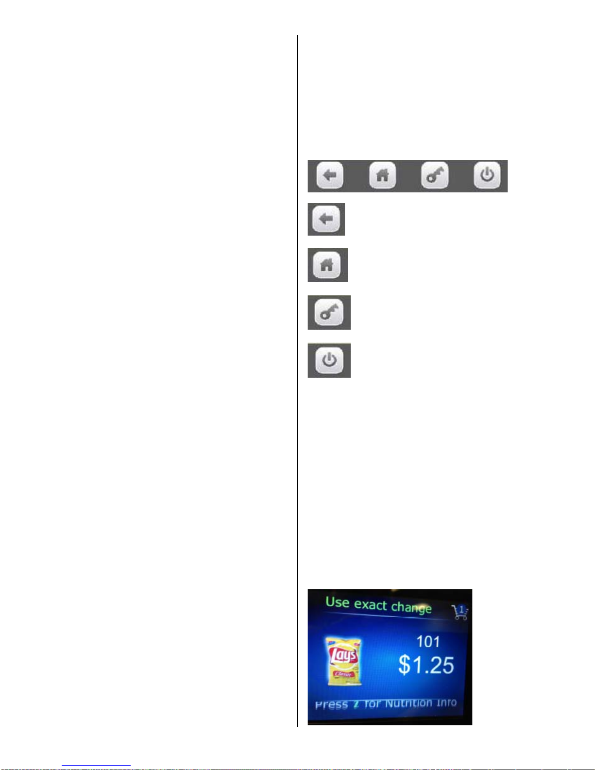
provide different menu options. They include
Driver Menu, Manufacturing Menu, and
Engineering Menu options. Information for
these modes is covered in the Security Codes
Mode programming section of this manual.
To Move through the Menu:
goes back one step in program.
goes back to the home menu screen.
not used at this time
not used at this time
DISPLAY of PRODUCTS and
NUTRITIONAL INFORMATION
Allows the consumer to view the product, cost, and
nutritional information of the selected product before
making a purchase. Crane Merchandising Systems is
providing the nutritional content information based on
information provided by the product manufacturers,
and Crane Merchandising Systems cannot accept
responsibility for content created by others.
• Press the product selection number. The
display will show a picture of the product
and the price of the product. Sample:
10 of 130
Page 12

• Press the icon as instructed to view the
nutritional information of the product. Sample:
Nutritional Information
Serving Size
Calories 240
% Daily Value
Total Fat 16g
25%
Sodium 250mg
11%
Total Carbohydrates 23g
8%
Sugar 1g
Protein 3g
Not a significant source of
Other nutrients
NORMAL OPERATION MESSAGES
At initial power-up, the program will start just like your
home computer and the Touch screen will display
Crane, followed by a running list of all activities being
checked during power up. The lights on vender will
cycle on and off, validator if installed will cycle, coin
return plunger motor will cycle, and then:
• If Errors exist, an error list will be displayed that
includes the time and date of the error. To exit or
escape to the home screen press the back arrow icon
on Touch Venders.
• If No errors exist, the home screen will appear with
programming menus.
INITIAL PROGRAMMING
TO VIEW DATA RECALL
To view a listing of the Data recorded for nonresettable sales data, resettable sales data, events,
and identification numbers enter the “DATA RECALL”
mode by opening the service door, entering the PIN
number, and pressing Data Recall icon on screen.
Use the top arrow and bottom arrow on the right side
of the screen to scroll through the multiple screens if
needed. Refer to the “Data Recall” programming
section for descriptions of available Data that is
recorded to be displayed.
TO VIEW ERRORS REGISTERED
To view a listing of errors along with the date and time
they occurred enter the “Diagnostics” mode by
opening the service door, entering the PIN number,
and pressing the Diagnostics icon. Use the top arrow
and bottom arrow on the right side of the screen to
scroll through the multiple screens if numerous errors
have been recorded. Refer to the “Diagnostics”
programming section for error descriptions, probable
causes, and possible solutions for many of the errors
that may display.
TO TEST VENDER OPERATIONS
To test the different operations of the vender enter the
“Test” mode by opening the service door, entering the
PIN number, and pressing the Test icon. Follow the
menu prompts or refer to the “Test” programming
section in this manual for step by step instructions to
perform tests for vending, coin return motor, surround
lighting, screen, refrigeration, MagTech Head,
cashless system, monetary, port & cup sensors,
platform movement, and lighting.
TO SET PRICES
To set the prices enter the “Price” mode by opening
the service door, entering the PIN number, and
pressing the Price icon. Follow the menu prompts or
refer to the “Price” programming section in this
manual for step by step instructions. This menu
allows you to set regular prices for an individual item,
a complete tray, or the entire machine. For other
pricing options you need to refer to the following
programming sections: “Special Vend Modes” or
“Timed Events”.
TO SET DATE/TIME
To set the date and time enter the “System Settings”
mode by opening the service door, entering the PIN
number, and pressing the System Settings icon.
Follow the menu prompts or refer to the “Time & Date”
programming section in this manual for step by step
instructions.
TO SET NEW PIN
To set a new PIN enter the “Security Codes” mode by
opening the service door, entering the PIN number,
and pressing the Security Code icon. Follow the
menu prompts or refer to the “Security Codes”
programming section in this manual for step by step
instructions.
TO SET STS
To set Space to Sales open the service door, enter
the PIN number, and press the Product Configuration
icon, then press the FIFO Setup icon or refer to the
FIFO Setup programming section in this manual for
step by step instructions.
For all other options please refer to the programming
quick reference chart on the following pages and the
related programming section in this manual for step by
step instructions.
11 of 130
Page 13
BEVMAX MEDIA – PROGRAMMING MAP
SOFTWARE VERSION 10.7.2 KEYPAD
Page 12 of 128
Data Recall Pg Price Pg Special Vend Modes Pg System Settings Pg
1 Non-Resettable Sales Data 14 1 By Tray 1 37 1 Free vend 45 1 Machine Information 59
1. Overall Totals 14 2 By Tray 2 37 2 Winner Mode 45 2 Time & Date 60
2. by Tray 15 3 By Tray 3 37 1. Add Group 45 3 Language 62
3. by Product 15 4 By Tray 4 37 2. Delete Group 47 4 DTS (Data Transfer System) 63
4. Cash 16 5 By Tray 5 37 3. Edit Group 47 1. DTS Standby mode 63
5. Cashless 16 6 By Entire Machine 37 4. Winner Selections Mappings 48 2. DTS Audit List 63
6. Bill Data 16 7 By Individual Selection 38 3 Combo Vends 48 3. CA304/CA308 Data Type 64
2 Resettable Sales Data 17 1. Discount Type 48 4. OnBoard Cashless Data 64
1. Overall Totals 17
Product Configuration
2. Add New Combo 48 5. Data Reset on Transfer 64
2. by Tray 17 1 Selection Configuration 39 3. Delete Promotion 50 6. Event Data Reset on Transfer 64
3. by Product 18 1. Tray 1 39 4. Edit Promotion 51 7. Pass-Code Reset 64
4. Cash 18 2. Tray 2 39 5. Combo Vend Selection 52 8. DTS Cache Settings 65
5. Cashless 19 3. Tray 3 39 4 Token Enable 53 5 Software Updates 65
6. Bill Data 19 4. Tray 4 39 5 Rapid vend 53 6 Backup/Restore 66
7. Clear Data 19 5. Tray 5 39 6 Multivend Discount 54 7 Clone (copy) Configurations 67
3 Events 20 2 FIFO Set-Up 39
Monetary
1. Prepare Flash Drive 67
1. Power Losses 20 1. Add Group Menu 39 1 Coins In/Out 55 2. Create Config Clone 67
2. Door Events History 20 2. Delete Group 40 1. Stop Dispensing 55 3. Install Config Clone 67
4 Identification Numbers 21 3. Edit FIFO Group 41 2. 0.05 55 4. Remove Clone from Stick 67
Mech, Validator, Cashless 21 4. FIFO Mappings 42 3. 0.10 55 8 Clone (copy) Board 68
Diagnostics
3 UPC/EAN Codes 42 4. 0.25 55 9 Screen Brightness 68
1 Screen Data 21 4 Shopping Cart Set-Up 43 5. Set Up Channels 55 10 LED Color 68
2 Diagnostics Errors 22 1. Shopping Cart Size 43 2 Bill Validator 56 11 Idle Time Out 69
2. Max. Fund Amount 44 3 Coin Mechanism 56 12 Advertisements 69
Test
5 View Plan-O-Gram 44 4 Card Reader A 56 13 Custom Messages 70
1 Test Vend 33 1. Tray 1 44 5 Card Reader B 56 14 Automatic Reboot Settings 70
2 Coin Return Motor 33 2. Tray 2 44 6 On Board Cashless Enable 57 15 SKip Main Menu 70
3 Surround Lighting Test 34 3. Tray 3 44 7 Correct Change Parms 57
4 Screen Test 34 4. Tray 4 44 1. Declining Balance 57
5 Refrigeration System 34 5. Tray 5 44 2. Force Vend 57
Security Codes
6 MagTeck Head Test 35 3. Accept on low change 57 1 Enter PIN 71
7 Cashless system test 35 4. Low change message 58 1. Details for Driver PIN 71
8 Monetary 35 5. Credit for failed vend 58 2. Details for Operator PIN 71
9 Port & Cup Sensors 36 6. Allow consumer over pay 58 3. Details for Engineers PIN 73
10 Platform Movement 36 8 Stack Bills 58 4. Details for Manufacturers PIN 74
11 Turn Lighting Off 37 1. Wait 58 2 Change Driver PIN 71
2. Stack Immediately 58 3 Change Operator PIN 71
9 Cash Discount 58
Page 14
BEVMAX MEDIA – PROGRAMMING MAP
SOFTWARE VERSION 10.7.2 KEYPAD
Page 13 of 128
Timed Events
1 Time of Day Events 77
1. Price Adjust 77
2. Free Vend 79
3. Inhibit 81
2 Backup Events 82
3 Power Savings Events 83
Telemetry
1 Assign Unit 84
2 Ping Server 86
3 Get Network Status 86
4 Show Network Config 87
5 Load Network Config 87
6 Radio Setup 87
7 How Telemetry Works 90
8 Definitions 91
Machine Configuration
1 Refrigeration Settings 93
2 Space to Sales 94
3 Picker Cup Sensor 95
4 Port Sensor 95
5 Manual Key Switch 95
6 Firmware Information 96
Cabinet Offsets 96
EVS Compliance 96
Shelf Location 97
Model # 97
Encoder Resolution # 97
Page 15
BEVMAX MEDIA – PROGRAMMING MAP
SOFTWARE VERSION 10.7.2 Touch
1. DATA RECALL……………………………Press icon to bring up a list.
Press the Data Recall icon brings up a list of the groups in this function.
Data Recall
Non Resettable Sales Data >
Resettable Sales Data >
Events >
Identification Numbers >
1. Non-Resettable Sales Data – Press the icon to bring up a screen
Press the Non Resettable icon will bring up a screen listing the sub-groups that contain
the data in this group.
TECH TIP – The listings in this group are a running total and will not be reset when a
DEX read is done or the “DATA CLEAR” function is used.
Non Resettable Sales Data
Over-All Totals >
By Tray >
By Product >
Cash >
Cashless >
Bill Data >
1. Overall Totals – Press the icon to bring up a table listing data.
Press the screen to choose a group.
Choosing a group will bring up the first screen in
the chosen group.
Press an icon to choose a Sub-Group.
Choosing a Sub-Group will bring up the first
screen in that Sub-Group.
Overall Totals
#
Sales $0.00 0
Discounts $0.00 0
Surcharge $0.00 0
Test Vend $0.00 0
Free Vend $0.00 0
Token Vend $0.00 0
Page 14 of 128
Page 16
BEVMAX MEDIA – PROGRAMMING MAP
SOFTWARE VERSION 10.7.2 Touch
2. By Tray – Press the icon to bring up a screen listing all trays.
Press icon to select a tray and you will bring up a screen with a table listing data as
shown.
By Tray
Tray #1 >
Tray #2 >
Tray #3 >
Tray #4 >
Tray #5 >
Tray 1 Data
#
Sales $0.00 0
Discounts $0.00 0
Surcharges $0.00 0
Test Vend $0.00 0
Free Vend $0.00 0
3. By Product – Press the icon to bring up a screen listing all trays
Press an icon to select a tray and you will bring up a screen listing the product selections
on that tray.
By Product
Tray #1 >
Tray #2 >
Tray #3 >
Tray #4 >
Tray #5 >
Tray #1
101 101>
102 102>
103 103>
104 104>
105 105>
106 106>
107 107>
108 108>
109 109>
Press an icon to select an individual product selection and you will bring up a table listing
dollar values and number of vends for that product. This table includes a line to include
the Price of the product set in the selection. The date and time of the last vend of the
selected product is displayed below the table.
101
#
Price $0.00
Sales $0.00 0
Discounts $0.00 0
Surcharge $0.00 0
Test Vend $0.00 0
Free Vend $0.00 0
Last Vend Date / Time
Page 15 of 128
Page 17
BEVMAX MEDIA – PROGRAMMING MAP
SOFTWARE VERSION 10.7.2 Touch
4. Cash – Press the icon to bring up a table listing Cash Data.
.
Cash
#
Cash In $0.00 ______
To Cash Box $0.00 ______
To Tubes $0.00 ______
Bills In $0.00 ______
Dispensed $0.00 ______
Manual Dispensed $0.00 ______
Sales $0.00 0
Discounts $0.00 0
Surcharge $0.00 0
Over Pay $0.00 0
5. Cashless – Press the icon to bring up a table listing Cashless Data.
Cashless A #
Sales $0.00 0
Discounts $0.00 0
Surcharge $0.00 0
Revalue $0.00 0
Cashless #
Sales $0.00 0
Discounts $0.00 0
Surcharge $0.00 0
Revalue $0.00 0
6. Bill Data – Press the icon to bring up a table listing Bill Data.
The contents of the recycler unit have been listed below the table.
Bill Data
In Out
One $0.00 $0.00
Two $0.00
Five $0.00 $0.00
Ten $0.00
Twenty $0.00
Fifty $0.00
Hundred $0.00
Recycler Contents $0.00
Page 16 of 128
Page 18
BEVMAX MEDIA – PROGRAMMING MAP
SOFTWARE VERSION 10.7.2 Touch
2. Resettable Sales Data – Press the icon to bring up a list
Press the icon will bring up a screen listing the sub-groups that contain the data in this
group.
TECH TIP – The listings in the resettable group are identical to the listings in the nonresettable group with the exception of the “CLEAR DATA” function which allows the
totals to be set back to Zero.
Resettable Sales Data
Overall Totals >
By Tray >
By Product >
Cash >
Cashless >
Bill Data >
Clear Data >
1. Overall Totals – Press the icon to bring up a table listing data.
Press the icon to choose a Sub-Group.
Choosing a Sub-Group will bring up the first
screen in the chosen Sub-Group.
Overall Totals
#
Sales $0.00 0
Discounts $0.00 0
Surcharge $0.00 0
Test Vend $0.00 0
Free Vend $0.00 0
Token Vend $0.00 0
2. By Tray – Press the icon to bring up a screen listing all trays.
Press a numeric Key to select a tray and you will bring up a screen with a table listing
data as shown.
By Tray
1) Tray #1 >
2) Tray #2 >
3) Tray #3 >
4) Tray #4 >
5) Tray #5 >
Tray 1 Data
#
Sales $0.00 0
Discounts $0.00 0
Surcharges $0.00 0
Test Vend $0.00 0
Free Vend $0.00 0
Page 17 of 128
Page 19
BEVMAX MEDIA – PROGRAMMING MAP
SOFTWARE VERSION 10.7.2 Touch
3. By Product – Press the icon to bring up a screen listing all trays
Press an icon to select a tray and you will bring up a screen listing the product selections
on that tray.
By Product
Tray #1 >
Tray #2 >
Tray #3 >
Tray #4 >
Tray #5 >
Press an icon to select an individual product selection and you will bring up a table listing
dollar values and number of vends for that product.
This table includes a line to include the Price of the
product set in the selection. The date and time of the
last vend of the selected product is displayed below
the table.
4. Cash – Press the icon to bring up a table listing Cash Data.
Cash
#
Cash In $0.00 ______
To Cash Box $0.00 ______
To Tubes $0.00 ______
Bills In $0.00 ______
Dispensed $0.00 ______
Manual $0.00 ______
Sales $0.00 0
Discounts $0.00 0
Surcharge $0.00 0
Over Pay $0.00 0
Tray #1
101 101>
102 102>
103 103>
104 104>
105 105>
106 106>
107 107>
108 108>
109 109>
101
#
Price $0.00
Sales $0.00 0
Discounts $0.00 0
Surcharge $0.00 0
Test Vend $0.00 0
Free Vend $0.00 0
Last Vend Date / Time
Page 18 of 128
Page 20
BEVMAX MEDIA – PROGRAMMING MAP
SOFTWARE VERSION 10.7.2 Touch
5. Cashless – Press the icon to bring up a table listing Cashless Data.
Cashless A
#
Sales $0.00 0
Discounts $0.00 0
Surcharge $0.00 0
Revalue $0.00 0
Cashless B
#
Sales $0.00 0
Discounts $0.00 0
Surcharge $0.00 0
Revalue $0.00 0
6. Bill Data – Press the icon to bring up a table listing Bill Data.
The contents of the recycler unit have been listed below the table.
Bill Data
In Out
One $0.00 $0.00
Two $0.00
Five $0.00 $0.00
Ten $0.00
Twenty $0.00
Fifty $0.00
Hundred $0.00
Recycler Contents $0.00
7. Clear Data – Press the icon to clear resettable data.
Press the icon will bring up a screen asking you if you are sure you want to clear the
resettable data. Respond by pressing the Yes or No icon.
Do you really want to clear all
Resettable data?
Yes No
This is also the data that is cleared each time the machine successfully transmits a
DEX file.
Page 19 of 128
Page 21
BEVMAX MEDIA – PROGRAMMING MAP
SOFTWARE VERSION 10.7.2 Touch
3. EVENTS – Press the icon to bring up a screen
Press the icon will bring up a screen which is divided into two sections.
The top section of the screen allows you to view recorded data for each type of event.
Events
Power Losses >
Door Events History >
Last Data Clear
Date/Time
Last Vend
Date/Time-Selection
Last Price Change
Date/Time
Last Clock Set
Date/Time
Last Health Control Event
Date/Time-Selection
Power Losses
Duration Date Time
1 hours 09 minutes 04/24/2013 08:26
0 hours 12 minutes 04/12/2013 17:30
The data is recorded in order of occurrence and can be a valuable diagnostic tool to
determine if a power outage is the cause of a reported problem.
2. Door Events History – Press the icon will bring up a screen listing data about recorded
door events.
Door Events History
Event date time
Open Door ##/##/## 00:00:00
Closed Door ##/##/## 00:00:00
Open Door ##/##/## 00:00:00
Closed Door ##/##/## 00:00:00
Open Door ##/##/## 00:00:00
Closed Door ##/##/## 00:00:00
Press the icon to bring up a list for each type
of event.
The Last Data Clear data would include
both a manual clear and a successful DEX
read.
1. Power losses – Press the icon to bring
up a listing of data about recorded power
losses or a message of “No Power Losses”
registered
The data is recorded in order of occurrence
and can be a valuable tool used to determine
if the door has been opened and closed at a
time when it should not have been.
Page 20 of 128
Page 22
BEVMAX MEDIA – PROGRAMMING MAP
SOFTWARE VERSION 10.7.2 Touch
4. Identification Numbers – Press the icon to bring up a screen.
Press the icon will bring up a screen listing the ID numbers for the devices listed or a
message “not connected’.
Identification Numbers
Bill Validator #############
Card Reader #############
Coin Mechanism ############
2. DIAGNOSTICS……………..Press the icon to bring up a screen.
Press the icon will bring up a screen listing the errors along with the time and date they
occurred or a message of “No Errors Registered” will display.
Diagnostics
time date
Coin Tube 1 Empty 14:35 04/12/2013
Cabinet not cooling 09:45 03/25/2013
Coin Tube 2 Empty 17:00 02/28/2013
This screen will automatically come up when the service mode is entered if errors
currently exist. You may use the icon to back up to a previous menu in the
service screens.
List of many of the Errors/causes/solutions follow:
Page 21 of 128
Page 23

Page 22 of 128
Error Description Probable Cause Possible Solutions
Stuck Keys Fatal. Stuck keys on keypad or shorted connections/harness. Check connectors to be properly installed.
Check harness for damage.
Replace the keypad.
No Monetary Device Fatal. The control board has not been able to detect a Check connectors to be properly installed.
working monetary device. Check harness for damage.
Check for faulty bill validator/harnessing.
Retest without the bill validator and harnessing
installed.
Replace the coin mechanism.
Coin Mech No Comms. No Communications are occurring between the Check connectors to be properly installed
coin mechanism and the control board. Check harness for damage
Retest without the bill validator and harnessing
installed.
Replace the coin mechanism.
Coin Mech ROM Error Coin Mech ROM Error Replace the coin mechanism.
Coin Mech Acceptor Coin Mech Acceptor Unplugged. Check the connections within the coin mechanism
Unplugged. Replace the coin acceptor.
Replace the coin Mechanism.
Coin Mech Acceptor Coins or other items are stuck in the acceptor Remove the coins or other items from the acceptor.
Jammed. causing the gate to remain open. Replace the acceptor.
Replace the coin mechanism.
Coin Mech Payout Jammed. Coin pay out motor or solenoid is stuck in cycle. Check for and remove bent coins or other items
causing the jam.
Replace the coin mechanism.
Coin Mech Sensor Error. Bad coin mechanism sensor. Check for an item causing a blockage and remove.
Replace the coin mechanism.
Coin Mech All Tubes Error. Coin mechanism not sensing any pay out tubes. Check for proper pay out cassette placement.
Replace the payout cassette.
Replace the coin mechanism.
Page 24

Page 23 of 128
ErrorDescription ProbableCausePossibleSolutions
Coin Mech Tube Error. Coin mechanism not sensing a payout tube. Check for proper pay out cassette placement.
Replace the payout cassette.
Replace the coin mechanism.
Coin Mech Disabled. Coin mechanism has been disabled by the board Power down the machine and re-start.
Remove bill validator and/or card reader from system.
Replace the coin mechanism.
Reset the control board.
Replace the control board.
Exec Price Error. Executive coin mechanism error. Check for a price set outside of allowed parameters.
Replace executive coin mechanism.
No Monetary Device. No monetary device detected by the board. Check connectors to be properly installed.
Check harness for damage.
Retest without the bill validator and harnessing
installed.
Replace the coin mechanism.
Coin Return Motor Not Control board not sensing the presence Check the connection J6 on the I/O board to the
Present. of a coin return motor. coin return motor.
Home the coin return motor.
Replace the coin return motor.
Check for damage to harnessing.
Reset or replace the control board.
Coin Return motor Run The board has determined that the coin Check the connections to the coin return motor.
Time Timeout. return motor should have arrived at home Home the coin return motor.
position, but it has not. Replace the coin return motor.
Check for damage to harnessing.
Reset or replace the control board.
Coin Return Motor Short Coin return motor has shorted out. Check connections and harnessing for damage.
Circuit. Replace the coin return motor.
Coin Return Motor Drive The coin return motor is not engaging the Check for damaged or missing drive linkage.
Failure. coin return arm on the coin mechanism. Check for proper mounting of coin mechanism.
Check for damage on coin mechanism pay out parts.
Page 25

Page 24 of 128
ErrorDescription ProbableCausePossibleSolutions
Low Change. The coin mechanism has reported a low or Add coins to the tubes using the coins in/out screen in
empty condition in one or more of the coin the monetary section of the service modes.
pay out tubes. Do vends with coins to add coins to the tubes.
Replace coin mechanism.
No IO Comm. The control board is not communicating with Check for proper connections on the I/O board.
the I/O board. Check for proper connections on the control board.
Check for damage to the harnessing.
Remove the monetary devices from the system and
check for restored communication.
Replace the I/O board.
Reset and/or replace the control board.
Please Wait. The board is asking you to wait while it completes Wait for the board to finish the operation.
an ongoing operation. Re-start the machine and let it re-boot.
Remove monetary devices and re-start the machine.
Reset and/or replace the control board.
No Selections Available. The control board is not sensing any motors Check for motors to be homed.
available for use. Check for motors and harnesses to be connected.
Check for power to I/O board.
Replace I/O board.
Reset and/or replace control board.
All Selections Disabled. The control board has disabled all the motors in Check SureVend settings and operation.
the machine. Check motors to be homed and connected properly.
Check for a timed event to be enabled causing the
Condition.
Check/replace I/O board.
Reset/replace control board.
IO Board Voltage. The control board has detected improper voltage Check voltage to the machine.
for I/O board operation. Check voltage to the I/O board.
Replace the I/O board.
Init Failed. The control board has failed to initialize successfully. Power down and re-start the machine.
Power down, disconnect monetary devices and
re-start the machine.
Replace the control board.
Page 26

Page 25 of 128
ErrorDescription ProbableCausePossibleSolutions
Health Control Active. The control board has detected a temperature Check for clean screens and condenser.
condition which is outside the allowed parameters Check for acceptable clearance behind the machine.
and has stopped allowing sales of involved products. Check temperature sensor for accurate readings.
Check refrigeration system for proper function.
Anti Jackpot Error. The control board has detected multiple attempts to Check SureVend calibration.
vend a product from a selection and has not seen a Check SureVend function.
successful delivery. Check motor function.
# XXX Sold Out. The control board has determined that a selection is Check to see that there is product.
sold out. (XXX indicates the selection number Check SureVend calibration.
involved). Check SureVend function.
Check motor function.
Factory Init. An attempt to restore factory default settings has Power down, power up, try again.
been unsuccessful. Power down, remove monetary devices and try again.
Replace the control board and reset.
Card Reader No Comms. The control board is not able to communicate with Check connections for the card reader.
the card reader. Check for damage to the harness (cut, pinched, etc.).
Replace the card reader.
Reset the control board.
Replace the control board.
Card Reader Comms Error. The control board is not communicating with the Check the connections and harness for damage.
Card reader. Check the settings on the board and on the reader.
Replace the reader.
Reset and/or replace the board.
Bill Validator No Comms. The control board is not communicating with the Check the connections and settings for the validator.
bill validator. Replace the harness.
Replace the validator.
Bill Validator Motor Error. The validator has reported an error to a drive motor Check for a broken belt or blockage.
within the validator. Replace the bill validator.
Bill Validator Sensor Error. The validator has reported an error to a sensor within Check for a sensor blockage.
the validator. Replace the bill validator.
Page 27

Page 26 of 128
ErrorDescription ProbableCausePossibleSolutions
Bill Validator ROM Erro. An error has been detected in a main chip in the Replace the bill validator.
Validator.
Bill Validator Acceptor A jam in the bill path has been detected. Check the bill path for items that are blocking sensors.
Jammed. Check to see that the bill path gates are not open.
Replace the bill validator.
Bill Validator Stacker Error. An error has been reported concerning the bill box. Check the bill box to be mounted to the validator
properly.
Replace the bill box.
Replace the bill validator.
Bill Validator Stacker Full. The bill validator is reporting that the bill box is full Check for bills and remove them.
of bills. Replace the bill box.
Replace the bill validator.
Bill Validator Disabled. The control board has disabled the bill validator. Check for coins in the payout tubes of the coin
Mechanism.
Check for a fault with the bill validator.
Check Winner Prize. The control board has detected a failed winner vend. Check for the presence of product.
Check motor function.
POWER OFF. The control board has detected a power outage. Check the power cord and plug.
Check the circuit breaker.
Check the On/Off switch in the machine.
DOOR OPEN. The control board is reporting that the door has Check to see if someone has been in the machine.
been opened. Check the door switch.
Check switch connections and harnessing for damage.
Power Save mode. The machine is in a power save event. Let the event complete.
Modify or eliminate the event in the software settings.
Sold Out Machine. The control board has determined that all selections Check SureVend settings and function.
in the machine are sold out. Check for vend motor function.
Check harnessing connections.
Check for board function (selection configuration).
Page 28

Page 27 of 128
ErrorDescription ProbableCausePossibleSolutions
Recycler Motor Problem. A problem has been detected with a motor inside Check for an obstruction or blockage within the
the bill validator. recycler which is stopping the motor from completing
its cycle.
Replace the bill validator.
Recycler Sensor Problem. A problem has been detected in a sensor within Replace the recycler cassette.
the recycler. Replace the bill validator.
Recycler Jam. The recycler is unable to function. Check for an obstruction or blockage which is
preventing the recycler from completing its cycle.
Replace the recycler cassette.
Replace the bill validator.
Recycler Checksum Error. A communications error has been reported Check the bill validator harnessing for damage.
between the recycler and the control board. Re-start the system to restore communication.
Replace the recycler.
Recycler Disabled. The recycler has been disabled by the control board. Check for proper function of the recycler unit (errors).
Check the recycler cassette for proper installation.
Replace the bill validator.
# XX Coin Mech Tube Empty. The coin mechanism is reporting that there is an Check for an empty tube and replenish.
empty payout tube. (# XX indicates which tube is Check for a bad sensor.
empty). Replace the coin cassette.
Replace the coin mechanism.
Bill Validator Stacker Motor An error has been reported concerning the stacker Check the bill path for a blockage preventing the
Error. Motor in the bill validator. proper operation of the bill stacker motor.
Replace the bill validator.
Bill Validator Recycler Gate An error has been detected in the recycler gate Check for an blockage in the bill path preventing the
Error. gate from functioning.
Replace the bill validator.
Bill Validator Recycler Tape An error has been reported in the operation of Check for a blockage in the bill path which prevents
Error. the recycler tape within the recycler cassette. the tape from moving backward and/or forward.
Replace the recycler cassette.
Replace the bill validator.
Page 29

Page 28 of 128
ErrorDescription ProbableCausePossibleSolutions
Optical Sensor Failure. The failure of an optical sensor within the Check the bill path for an obstruction or blockage
bill validator has been detected. which prevents the optical sensor from functioning.
Replace the bill validator.
Magnetic Sensor Failure. The failure of the magnetic sensor within the Check the bill path for an obstruction or blockage
bill validator has been detected. which prevents the magnetic sensor from functioning.
Replace the bill validator.
Recycler Cass Jammed. The recycler cassette is not able to move. Check for an obstruction or blockage which is
preventing the cassette from moving.
Replace the recycler cassette.
Replace the bill validator.
Bill Validator Path Jammed. A blockage of the bill path has been reported. Check for an obstruction or blockage which is
preventing the bills from moving thru the bill validator.
Replace the bill validator.
Bill Validator Cashbox The bill box has become jammed and is not Check for a full bill box
jammed. allowing the stacker motor to complete its cycle. Check for damaged bills blocking the operation of the
stacker plate.
Replace the bill box.
Replace the bill validator.
Stacker Out Of Position. The control board has detected that the stacker Check for a blockage or obstruction which is not
has stopped out of its home position. allowing the stacker motor to complete its cycle.
Check for proper installation of the bill box.
Replace the bill box.
Replace the bill validator.
Recycler Out Of Position. The recycler is not able to accept bills. Check for proper installation of the recycler cassette.
Check for an obstruction or blockage which is
preventing the cassette from locking into position.
Replace the recycler cassette.
Replace the bill validator.
Page 30

Page 29 of 128
ErrorDescription ProbableCausePossibleSolutions
X Motor Failure. The control board is reporting that the X motor is Check for proper connections to the motor.
not functioning. Check for damage to the harnessing.
Check for proper switch function.
Check for over tightening of the motor.
Replace the motor.
Y Motor Failure. The control board is reporting that the Y motor is Check for proper connections to the motor.
not functioning. Check for damage to the harnessing.
Check for proper switch function.
Check for over tightening of the motor.
Replace the motor.
Picker Motor The control board is reporting that the picker motor Use the position test functions to test the picker motor.
Failure. is not functioning. Replace the picker cup.
Port Motor The control board is reporting that the port motor Use the port test functions to test for function
Failure. is not functioning. Check wiring connections.
Check switch functions including the position cam.
Replace the motor.
Vend Timeout. The control board is reporting that a successful vend Check for a picker cup that did not return to the home
cycle has not been completed in the allowed amount position.
of time. Check for a port door that did not open/close."
Cabinet Failure. An error that has not yet been defined. Should not be seen in a machine.
Replace the control board.
Coin Return The control board is reporting that the coin return Check the wiring connections.
Motor Failure. Motor has failed. Check for proper mounting of the motor.
Check for proper mounting of the coin mechanism.
Replace the coin return motor.
Picker Home The control board has reported that the picker Use the position test functions to test or cycle the
Failure. has failed to return to its home position at the picker back to its home position.
end of a cycle. Replace the picker cup.
Temperature The control board is reporting that the Compare the reported temperature against a
Sensor Error. temperature sensor has failed. Thermometer.
Replace the temperature sensor.
Page 31

Page 30 of 128
ErrorDescription ProbableCausePossibleSolutions
Cooling System The control board is reporting that the refrigeration Check for a bad temperature sensor.
Not Cooling. system is not functioning. Check for other errors that would cause the
refrigeration system to have been shut down
by the board.
Cabinet Too Hot. The control board is reporting that the cabinet is Check for an accurate temperature reading.
operating at three degrees, or more, above the Check refrigeration system for proper function
allowed parameter. (clean screens, condenser also distance from rear wall).
Check for proper fan operation.
Cabinet Too Cold. The control board is reporting that the cabinet is Check for an accurate temperature reading.
operating at three degrees, or more, below the Check refrigeration system for proper function
allowed parameter. (clean screens, condenser also distance from rear wall).
Check for proper fan operation.
Card Reader Manuf Trans The card reader has reported an error in Check the card reader for proper function.
Error. transmitting data. Replace the card reader.
Card Reader Service Error. An internal error has occurred within the card Reset the card reader and retry.
reader. Replace the card reader.
Card Reader Manufact Error. An internal error has occurred within the card Reset the card reader and retry.
reader. Replace the card reader.
Card Reader Failed OOS Error. An internal error has occurred within the card Reset the card reader and retry.
reader. Replace the card reader.
Card Reader Comms OOS An internal error has occurred within the card Reset the card reader and retry.
Error. reader. Replace the card reader.
Card Reader Jam OOS Error. An internal error has occurred within the card Reset the card reader and retry.
reader. Replace the card reader.
Card Reader Manufact OOS An internal error has occurred within the card Reset the card reader and retry.
Error. reader. Replace the card reader.
Page 32

Page 31 of 128
ErrorDescription ProbableCausePossibleSolutions
Health Check Error. The control board is reporting that an error occurred Check temperature sensors for proper function.
in the process of conducting a health check. Check the refrigeration system for function.
Reset machine for another cool down period to check
for proper health control function.
Reset the control board to default settings and set up
for another test.
Replace the control board and re-test.
Heath Timer Error. The control board is reporting that an error has Reset machine for another cool down period to check.
occurred in the operation of the timer during a for proper health control function.
health check function. Reset the control board to default settings and set up
for another test
Replace the control board and re-test.
Health Recheck Error. The control board is reporting that an error Check temperature sensors for proper function.
occurred in the process of conducting a second Check the refrigeration system for function.
attempt at a health check. Reset machine for another cool down period to check
for proper health control function.
Reset the control board to default settings and set up
for another test.
Replace the control board and re-test.
Capacity Sensor Failure. An error has been reported with a sensor inside Re-start the bill validator and check function.
the bill validator. Replace the bill validator.
Not Calibrated Sensor Error. An error has been reported with a sensor inside the Re-start the bill validator and check function.
Bill validator. Replace the bill validator.
X Motor Home Failure The X motor home switch is not detected. Check XY Assy is all the way to the left at the top.
Replace the X Home Switch.
Replace the Atlas Board.
Y Motor Home Failure The Y motor home switch is not detected. Check XY Assy is all the way to the left and Delivery
Cup is all the way to the bottom.
Replace the Y Home Switch.
Replace the Y Board.
Replace the Atlas Board.
Page 33

Page 32 of 128
ErrorDescription ProbableCausePossibleSolutions
Picker Home Failure The picker home switch is not detected. Check the plunger is all the way in at the home position.
Replace the Picker Home Switch.
Replace the Delivery Cup Assy.
Replace the Y Board.
Replace the Atlas Board.
Port Open Error The port closed switch is not detected. Check the port door is all the way closed.
Replace the Port Closed Switch.
Replace the Port Assy.
Replace the Atlas Board.
Page 34

3. TEST
Press the icon will bring up a screen listing the functions within the group.
Test
Test Vend >
Coin Return Motor >
Surround Lighting Test >
Screen Test >
Refrigeration Test >
MagTeck Head Test >
Cashless system test >
Monetary >
Port and Cup Sensors >
Platform Movement >
Turn Lighting Off >
1. Test Vend – Press the icon will bring up a screen.
Test Vend
Credit $0.00
Credit Card
Token
Select Product 101
Price $0.00
Start Vend >
2. Coin Return Motor – Press the icon to activate the test.
Press the icon will run one cycle on the coin return motor and display will show a success message if
motor runs.
Test
Test Vend >
Coin Return Motor >
Surround Lighting Test >
Screen Test >
……………….........................Press the icon to bring up a screen.
Press the icon to choose a function.
Use the top arrow and bottom arrow on the right side of the screen
to scroll through the multiple screens if needed.
Choosing a function will bring up the first screen within each
function.
Insert coins, bills or tokens to increase credit amount. If an MDB
cashless device is present or the onboard cashless interface is used
in the machine, the user may swipe a card to establish credit to test
function.
Press the Select product icon opens a window allowing you to enter
another selection using the numeric icons. Press the “Done” icon
to save. Press the “Start Vend” icon to run the selected motor.
Note: The left door switch must be pulled to the out position for the
XY to move.
Success
Page 33 of 128
Page 35

3. Surround Lighting Test – Press the icon to enter the function.
Press the icon brings up a screen listing one option.
Surround Lighting Test
Perform test >
Press the icon to perform the test. The display will say “Surround Lights should change now” and the
integrated payment openings lights will turn on, change colors, and turn off, then the pill light tube will
turn on, change colors, then turn off.
Surround Lighting Test
Surround lights should change now
4. Screen Test – Press the icon to enter the function.
Press the icon will bring up a screen with four colored bands which get progressively brighter.
Green
Blue
Red
White
The colors from left to right are Red, Green, Blue and at the bottom White.
5. Refrigeration System – Press the icon to enter the function
Press the icon will bring up a screen which displays the data
listed.
Test
Return Air 71°F
Refrigeration State 0
Turn Compressor On >
Turn Evaporator Fan On >
Return Air is the temperature of the air inside the vender.
Refrigeration State is an unused field and does not represent
anything.
Turn Compressor On, if you press icon it will toggle to off.
At this state the compressor is On or running.
Turn Evaporator Fan On, if you press icon it will toggle to off. At this the fan is On or running.
Page 34 of 128
Page 36

6. MagTeck Head Test – Press the icon to enter the function.
Press the icon will bring up a screen and the top portion is asking you to swipe your card.
MagTeck Head Test
Please swipe card
Swiping your card will tell you if it was a good or bad swipe
and on which tracks data was detected.
Good / Bad Swipes 0 / 0
Last Swipe Information
Track 1 0
Track 2 0
Track 3 0
7. Cashless system test – Press the icon to enter the function.
Press the icon will bring up a screen and the top portion will read “Please Swipe Card”. The bottom of
the screen will tell you the most recent swipe status.
Cashless system test
Please swipe card
Most recent swipe status
8. Monetary – Press the icon to bring up a
screen.
Press the icon will bring up the screen that shows data
about the coin mechanism and the bill validator.
When there are empty columns with no column header,
it simply means we are using a pre-built Flash table. It
provides room for future data to be inserted.
If no Mech or Validator is detected the screen will
show a message. Example - Error: no bill validator
detected. Please attaché one and enable it in Money
menu.
Monetary
Coin Mechanism
Coin
$0.05
$0.10
$0.25
Bill Validator
$1.00
$5.00
Token
Page 35 of 128
Page 37

9. Port and Cup Sensors – Press the icon to bring up a screen.
Port and Cup Sensors
Port Sensor
Sensor off
Vend detect off
Port Open Switch off
Port Closed Switch on
Turn Port Sensor On >
Open Port >
Picker Cup Sensor
Sensor off
Vend Detect off
Picker Motor Home on
Picker Motor out off
Turn Cup Sensor On >
Cycle Cup Plunger >
Data lists the current state concerning the Port Sensor.
Use the icon to Change the state concerning the Port
Sensor.
Data lists the current state concerning the Picker Cup
Sensor.
Use the icon to Change the state concerning the Cup
Sensor.
10. Platform Movement – Press the icon to bring up a screen.
Press the icon will bring up a screen allowing you to turn the components on and off.
Platform Movement
X Home On
Y Home On
Picker Motor Home On
Picker Motor out Off
Port Open Off
Port Close On
Door Switch Opened
Motor Positions 10005 9919
Select ‘0’ to ‘home’ the platform
Move to Selection
Cycle Cup Plunger >
Data listed is showing the current state of the various
switches as seen by the machine.
Motor positions: number on right is vertical motor counts;
number on left is horizontal motor counts.
Press the Move to Selection icon opens a window allowing
0
you to enter a selection number using the numeric icons.
Press the “Done” icon to move XY to the selection. Press
the “Cycle Cup Plunger” icon to cycle the plunger and
vend product from the column selected. Note: The left door switch must be pulled to the out position for
the XY to move & plunger to cycle. Press the Move to Selection icon opens a window allowing you to
enter a selection number using the numeric icons. Enter “0”, and then press the “Done” icon to move
XY to the home position.
Page 36 of 128
Page 38

11. Turn Lighting Off – Press the icon to bring up a screen.
Press the icon will bring up a screen allowing you to turn the Vertical Lighting on and off.
Press the icon will toggle the state of the Vertical Lights
between On and Off.
Test
Platform Movement >
Turn Lighting Off >
Note: The top LEDs are not controlled by this switch.
4. PRICE ……………………… Press the icon to bring up a pricing screen.
Pricing of selections can be accomplished in three ways with the pricing screen open.
BY TRAY
Price
Price for Tray #1
$0.00
Price for Tray #2
$0.00
Price for Tray #3
$0.00
Price for Tray #4
$0.00
Price for Tray #5
$0.00
Entire Machine
$0.00
Individual Price >
BY ENTIRE MACHINE – Press the icon to enter Price for Entire Vender.
Press the icon to select Entire Machine, and a window will open allowing you to enter a new price using
the numeric icons. Press the “Done” icon to accept the new pricing.
Press an icon, to select a Tray (1 to 5) and a window will
open allowing you to enter a new price.
Press the numeric icons to enter a new price for all
selections on the selected tray.
Press the “Done” icon to accept the new pricing.
Price
Entire Machine
Individual Prices >
$0.00
Page 37 of 128
Page 39

BY INDIVIDUAL SELECTION – Press the icon to enter Price for Individual Selection.
Press the icon to select Individual Prices and a tray list will come up.
Individual Prices
Tray 1 >
Tray 2 >
Tray 3 >
Tray 4 >
Tray 5 >
Press an icon to select a tray and you will bring up a screen listing
the product selections on that tray.
Tray #1
101
$0.00
102
$0.00
103
$0.00
104
$0.00
105
$0.00
106
$0.00
107
$0.00
108
$0.00
109
$0.00
Press an icon to choose a selection will open up a window allowing
you to enter a new price.
Press the numeric Key icons to enter a new price for the chosen
selection.
Press the “Done” icon to accept the new pricing.
5. PRODUCT CONFIGURATION ……..Press the icon to bring up a screen.
Press the icon brings up a screen listing the various functions.
Product Configuration
Selection Configuration >
FIFO Setup >
UPC/EAN Codes >
Shopping Cart Setup >
View Planogram >
Press an icon will bring up the first screen in the function
selected.
Page 38 of 128
Page 40

1. Selection Configuration – Press the icon to bring up a screen.
Press the icon will bring up a screen with a tray list.
Selection Configuration
Tray #1 >
Tray #2 >
Tray #3 >
Tray #4 >
Tray #5 >
Use the icon to choose a tray and bring up a screen listing the
selections on the chosen tray.
Tray #1
101 √
102 √
103 √
104 √
Check marks will indicate the active selections.
Use the numeric icons to check or un-check selections as needed.
105 √
106 √
107 √
108 √
109 √
When selections are complete press the to return to
Selection Configuration, Tray selections screen.
2. FIFO Setup – Press the icon to bring up a screen.
This screen will only show Add Group Menu if no Groups have
FIFO Setup
Add Group Menu >
Delete Group >
Edit FIFO Group >
FIFO Mappings >
been created. It will be expanded to include options in grey after a
group is added. Press the Add Group Menu icon to add a group.
1. Add Group Menu - Press the icon to bring up a screen to create group(s).
The Tray icons are used to add a group of selections that will
operate in FIFO mode. Included selections will be listed on the
Add Group Menu
Create Group nothing selected
Trays
Tray #1 >
Tray #2 >
Tray #3 >
Tray #4 >
Tray #5 >
right side of the Create Group window.
Once the selections have been added to the group, It must
be saved by pressing the Create Group icon to create the
group, or your work will be lost!
Selecting a tray will bring up a screen that will allow you to
choose selections that will be included in the group. A group
can include selections on more than one tray.
Page 39 of 128
Page 41

Tray
Set All >
Clear All >
101 √
102 √
103 √
104 √
105 √
106 √
107 √
108 √
109 √
Press the Set All icon will include all selections on the tray in the
group. A check will appear for each selection. Press the Clear All
icon will remove all selections on the tray from the group. All
checks for selections will disappear.
Press an icon for an individual selection will check or un-check
that selection. Checks will appear for selections included in the
group and disappear for selections not included in the group.
Use the top arrow and bottom arrow on the right side of the screen
to scroll through the multiple screens if needed.
Once the selections have been added to the group, It must be
saved by pressing the Create Group icon to create the group,
or your work will be lost!
Once a group has been created, the original screen will be expanded to include more functions for
managing the FIFO operations.
FIFO Setup
Add Group Menu >
Delete Group >
Edit FIFO Group >
FIFO Mappings >
2. Delete Group – Press the icon to bring up a screen listing the existing groups.
Delete Group
Delete Group #1 >
Delete Group #2 >
Delete Group #3 >
Use the icon to select the group to be deleted and a screen will come
up asking if you are sure you want to delete the group.
Yes No
Are you sure you want to
Delete group #1?
Respond using the Yes/No icons.
Page 40 of 128
Page 42

Once a selection is made a screen will come up reminding you prices will remain the same as they
were set in the FIFO group settings.
Please modify using the Price menu if needed.
All individual prices will remain
as they were set in the FIFO group.
OK
3. Edit FIFO Group – Press the icon to bring up a screen listing the existing groups that you or
others have created.
Use an icon to choose a group to be edited and a
screen will come up which will allow you to edit
Edit Group #1 >
Edit Group #2 >
Edit FIFO Group
the chosen group.
Use the Save Group icon to save the changes made
to the group.
If you do not save the changes you make by pressing
the Save Group icon, your work will be lost!
Use the icons to select a tray to edit.
Edit FIFO Group
1) Save Group 301, 302, and 7 more>
Trays
1) Tray #1 >
2) Tray #2 >
3) Tray #3 >
4) Tray #4 >
5) Tray #5 >
Once a tray is selected a screen will come up that will allow you to edit all the selections on that tray.
Tray #1 FIFO Selections
Set All >
Clear All >
101 √
102 √
103 √
104 √
Press the Set All icon will include all selections on the tray
in the group. A check will appear for each selection. Press
the Clear All icon will remove all selections on the tray
from the group. All checks for selections will disappear.
Press an icon for an individual selection will check or uncheck that selection from the group. Checks will appear
and disappear for the chosen selection.
105 √
106 √
107 √
108 √
109 √
When selections are complete press the to return
to Edit FIFO Group and press the Save Group icon to save
changes.
If you do not save the changes you make by pressing the Save Group icon, your work will be lost!
Use the top arrow and bottom arrow on the right side of the screen to scroll through the multiple screens
if needed.
Page 41 of 128
Page 43

Remember to return to the screen with “SAVE GROUP” icon; press the Save Group icon to save
the changes you have made to the group or your changes will be lost!
4. FIFO Mappings – Press the icon to bring up a tray list.
Use an icon to bring up a list of the selections on the selected tray.
FIFO Mappings
Tray #1 >
Tray #2 >
Tray #3 >
Tray #4 >
Tray #5 >
Tray # 2 FIFO Selections
201 Group #1
202 Group #1
203 Group #1
204 unassigned
205 unassigned
206 unassigned
207 unassigned
208 unassigned
209 unassigned
The selection list will tell you what group each selection is
assigned to, or that it is unassigned.
Some selection lists use more than one screen. Use the top arrow
and bottom arrow on the right side of the screen to scroll through
the multiple screens if needed.
4. UPC (Universal Product Codes)/EAN(Article Numbering System) Codes – Press the icon
to bring up a list.
UPC/EAN Codes
Clear all Products >
Tray #1 >
Tray #2 >
Tray #3 >
Tray #4 >
Tray #5 >
Press the icon will bring up a tray list of UPC/EAN Codes.
Press an icon to choose a tray. Choosing a tray will bring up a
screen listing all the selections on that tray.
Page 42 of 128
Page 44

The “UPC/EAN Code” will be listed on the same line as the
Tray #2
Clear all Products >
201 201
202 202
203 203
204 204
205 205
206 206
207 207
208 208
209 209
selection. The code is the same as the selection number.
Press the numeric icons for a selection will open a window that
will allow you to set another code number for that selection
using the numeric keypad.
All UPC/EAN codes are numeric only, you cannot enter letters.
You can use the “Shopping Cart” button to delete a character.
Press the “Done” icon to accept the changes to the code, or use the X icon to back out.
Some selection lists use more than one screen. Use the top arrow and bottom arrow on the right side of
the screen to scroll through the multiple screens if needed.
4. Shopping Cart Set-Up – Press the icon to bring up a list.
Press the ion brings up a screen listing two options for setting up the shopping cart function.
Shopping Cart Setup
Shopping cart size
3
Max Fund Amount
$0.00
1. Shopping Cart Size – Press the icon opens a window allowing you to set
the maximum number of items to be placed in the shopping cart so they can
be purchased in one transaction.
Shopping Cart Setup
1) Shopping cart size
3
2) Max Fund Amount
$0.00
Use the numeric icons to edit the number of items that may be placed in the
cart. The maximum number of items that can be placed in the cart is eight (8).
Use the “Done” icon to accept the change.
Page 43 of 128
Page 45

2. Maximum Fund Amount – Press the icon opens a window allowing you to set the maximum value
of items placed in the shopping cart.
Shopping Cart Setup
1) Shopping cart size
3
2) Max Fund Amount
$0.00
The recommended value should be calculated by multiplying the number of
items allowed in the cart by the highest price set in the machine.
Use the numeric icons to edit the value of the items.
Use the “Done” icon to accept the change.
5. View Planogram – Press the icon to bring up a tray list.
Press the icon will bring up a tray list.
101
101 102 103 104 105 106 107 108 109
$0.00 $0.00 $0.00 $0.00 $0.00 $0.00 $0.00 $0.00 $0.00
201
201 202 203 204 205 206 207 208 209
$0.00 $0.00 $0.00 $0.00 $0.00 $0.00 $0.00 $0.00 $0.00
301
301 302 303 304 305 306 307 308 309
$0.00 $0.00 $0.00 $0.00 $0.00 $0.00 $0.00 $0.00 $0.00
401
401 402 403 404 405 406 407 408 409
$0.00 $0.00 $0.00 $0.00 $0.00 $0.00 $0.00 $0.00 $0.00
501
501 502 503 504 505 506 507 508 509
$0.00 $0.00 $0.00 $0.00 $0.00 $0.00 $0.00 $0.00 $0.00
102
202
302
402
502
103
203
303
403
503
104
204
304
404
504
105
205
305
405
505
106
206
306
406
506
107
207
307
407
507
108
208
308
408
508
109
209
309
409
509
The tray list will show you the selections on the tray along with the product codes and prices.
Press the X (delete) icon to back out.
Custom Planograms can be downloaded in the machine from a memory (USB) stick.
X
Page 44 of 128
Page 46

6. SPECIAL VEND MODES ……Press the icon to bring up a screen.
Press the icon will bring up a screen listing all of the functions that can be accessed within this group.
Use the icons to choose a function.
Special Vend Modes
Free vend Off
Winner Mode >
Combo Vends >
Token Enabled >
Rapid Vend No
MultiVend Discount >
1. Free vend – Press the icon.
Press the icon will toggle an entry in a window on the first screen between On
and Off.
Special Vend Modes
1) Free vend Off
2. Winner Mode – Press the icon to bring up a screen.
Press the icon will bring up a screen that will prompt you to press the Add Group icon.
Winner Mode
Add Group >
Press the icon will bring up a screen allowing you to create a group of selections to operate in the
Winner Mode. It is divided into multiple sections.
1. The Add New Winner Group icon is used to
save the group you create. If you fail to save
the group you create, your work will be
lost!
Press the Mode icon allows you to toggle the setting
between Winner and Prize. If Winner is selected, the
chosen product is given and credit returned. If Prize
is selected, the chosen product is given and a second
product (the Prize) is also given.
Press the Frequency icon allows you to determine the
frequency or how often a Winner Vend happens,
based on the number of successful vends completed.
Press the numeric icons to set the number of vends.
Press the “Done “ icon to save the number set.
Use the icon to toggle between On and Off for the Free Vend
function.
Choosing a function will bring up the first screen of the
chosen function.
This screen has only one option at this point.
Once a group has been created, this screen will be expanded to
include more options for control and editing of the group.
Add Group
Add New Winner Group
nothing selected
Parameters
Mode Prize
Frequency 100
Prize 101
Trays
Tray #1 >
Tray #2 >
Tray #3 >
Tray #4 >
Tray #5 >
Page 45 of 128
Page 47

The Prize icon only appears if the Prize Setting has been chosen in the Mode menu.
Press the Prize icon will open a live window allowing you to enter the selection number for the product
that will be given as a Prize in a winner vend, using the numeric icons. Press the “Done” icon to save
the number set.
The last section of the screen is a tray list. Use an icon to choose a
tray. The icons will vary depending on your previous choice of
Tray #2 Winner Selections
Set All >
Clear All >
201 √
202 √
203 √
204 √
205 √
206 √
207 √
208 √
209 √
Winner or Prize.
Choosing a tray will bring up a screen that displays the selections
on the chosen tray. There is a second screen.
Use the Set All icon to include all the selections on the tray in the group. Use the Clear All icon to
remove all selections on the tray from the group.
Use the selection icons to check or un-check the selections to be included or removed from the group.
Checked selections are the selections included in the group. Some selection lists use more than one
screen. Use the top arrow and bottom arrow on the right side of the screen to scroll through the multiple
screens if needed.
Use the to leave one tray so that you can enter another. Selections can be chosen for a group
from all trays.
Once all your choices have been entered, you MUST return to Add New Winner Group Group
icon on the screen and press it to save the group. This will save all your choices and create a
group. If you fail to save the data for your group, the data will be lost!
Once a group has been created, the original screen will be expanded to include more functions for
managing the Winner Mode function.
Winner Mode
Add Group >
Delete Group >
Edit Group >
Winner Selections >
Page 46 of 128
Page 48

2. Delete Group – Press the icon to bring up a screen listing the existing groups.
Delete Group
Delete Group #1 >
Delete Group #2 >
Use the icons to select the group to be deleted and a screen will
come up asking if you are sure you want to delete the group.
Yes No
Are you sure you want to
delete group #2?
Respond using the Yes or No icon.
3. Edit Group – Press the icon to bring up a screen listing the existing groups.
Edit Group
Edit Group #1 >
Edit Group #2 >
Use an icon to choose a group to be edited and a screen will come
up which will allow you to edit the group.
Edit Group #1
1) Save Group 101, 102 and 7 more>
Parameters
Mode Prize
Frequency 100
Prize 101
Trays
Tray #1 >
Tray #2 >
Tray #3 >
Tray #4 >
Tray #5 >
Press the Set All icon will include all selections on the tray in
the group. A check will appear for each selection.
Press the Clear All icon will remove all selections on the tray
from the group. All checks for selections will disappear.
Use the Save Group icon to save the changes made to the
group.
Use the icon to select a tray to edit. Once a tray is selected a
screen will come up that will allow you to edit all the
selections on that
tray.
Edit Group
Set All >
Clear All >
201 √
202 √
203 √
204 √
205 √
206 √
Page 47 of 128
Page 49

Press an icon for an individual selection will include or remove that selection from the group. Checks
will appear and disappear for the chosen selection.
Some selection lists use more than one screen. Use the top arrow and bottom arrow on the right side of
the screen to scroll through the multiple screens if needed.
Checked selections are included in the Group.
When you have finished Editing, you MUST return to the screen with “SAVE GROUP” and press
the Save Group icon to save the changes you have made to the group. If you fail to save your
changes, the changes will be lost!
4. Winner Selections Mappings – Press the icon to bring up a screen.
Press the icon will bring up a screen listing all the trays.
Winner Selections Mappings
Tray #1 >
Tray #2 >
Tray #3 >
Tray #4 >
Tray #5 >
Choosing a tray will bring up a list of the selections on that tray.
The right side of the selection list will tell you what group each
selection is assigned to, or that it is unassigned.
Use an icon to choose a tray.
Tray #2 Winner Selections
201 Group #1
202 unassigned
203 unassigned
204 unassigned
205 unassigned
206 unassigned
207 unassigned
208 unassigned
209 unassigned
3. Combo Vends – Press the icon to bring up a screen.
Press the icon will bring up a screen listing two options.
Combo Vends
Discount Type Percent
Add New Combo >
Delete Promotion >
Edit Promotion >
Combo Vend Selection >
1. Press the Discount Type icon will toggle the
setting in a window between Value and Percent.
This will set the way the discount is used, either
a set monetary amount (value) or as a
percentage of the purchase.
Press the Add New Combo icon will bring up a screen
allowing you to create a new combo group.
Once a group has been created, the original screen will be expanded to include more options for
control and editing of the group. See in grey above.
Page 48 of 128
Page 50

The Add New Combo icon is the save button
Add New Combo Promotion
Add New Combo Promotion
for your Combo. If you fail to save the combo
you create, your work will be lost!
Groups Not Selected>
Number of Groups in Promotion 2
Discount Percentage 0
Discount All No
Edit Group 1 0 Selected>
Edit Group 2 0 Selected>
Enable Custom Message Yes
Message (only visible when Enable is set to Yes)
1. Press the Add New Combo icon once you have created it. If you do not use this icon to SAVE YOUR
WORK after you are done with all the other settings, your work will be lost!
Note: this functionality is available as long as you have selections assigned to the combo groups.
2. Press the Number of Groups in Promotion icon will toggle the active setting in the window between 2
and 3 Number of Groups in the Combo Promotion. This setting determines the number of groups of
products that will be involved
in the Combo.
A. The 2 setting will involve two groups of products.
Example – (Chips, Candy Bar)
B. The 3 setting will involve three groups of products.
Example – (Chips, Candy Bar, Cold Drink)
If 3 setting is selected, an additional line will appear further down in your screen. It will have the title of
“Edit Group 3” and show the number selected as do the other two groups. The icons for the functions
below will also shift to reflect the additional line.
3. Press the Discount Percentage icon will open a window that will allow you to enter a Discount
Percentage for the promotion using the numeric icons. Press the “Done” icon to accept the new number.
4. Press the Discount All icon will toggle the active setting in the window for Discount All between Yes
and No.
A. Selecting YES will apply the discount to each of the items in the Combo.
B. Selecting NO will apply the discount to only the last item in the Combo.
5. Press the icon to Edit Group1 will bring up a tray list.
A. Choosing a tray icon will bring up a screen listing all the selections on that Tray . The
list has more than one screen.
B. The checked selections are the selections that are currently included in the group.
C. Use the numeric icons to check or un-check selections as needed.
6. Press the icon to Edit Group 2 will bring up a tray list
A. The editing of Group 2 is the same as for Group1.
Page 49 of 128
Page 51

7. Press the icon to Edit Group 3 (if Number of Groups in was set to 3) will bring up a tray list.
A. This option will only appear if the three group setting has been chosen
previously with the Number of Groups in Promotion menu.
B. The editing for Group 3 is the same as for Group1.
8. Pressing the “Enable Custom Message” icon will toggle the setting in the live window between Yes and
No. When Yes is selected, an additional line will appear at the bottom of the screen titled “Message”.
9. Press the icon for “Message” will open a live window allowing you to enter a custom message using a
alpha numeric keypad.
Add New Combo Promotion
Message
A B C D E F G
H I J K L M N
O P Q R S T U
V W X Y Z
123 Aa #@ X Done
Press the icons on the display to cycle between alpha (upper case & lower case) and numeric (123)
characters. Once your message is complete, press the “Done” icon to save message.
Once a group has been created, the original screen will be expanded to include more options for
control and editing of the group.
Combo Vends
Discount Type Percent
Add New Combo >
Delete Promotion >
Edit Promotion >
Combo Vend Selection >
Press the Discount Type icon will toggle the setting in a
window between Value and Percent.
This will set the way the discount is used, either a set
monetary amount or as a percentage of the purchase.
Press the Add New Combo will bring up a screen allowing you to create Another New Combo group.
The new Combo Group will be created in the same way as the first, with all the same rules in effect.
Press the Delete Promotion icon will bring up a screen listing the existing groups that can be deleted.
Delete Promotion
Delete Promotion #1 >
Delete Promotion #2 >
Page 50 of 128
Page 52

Use the Yes or No icon to select the group to be deleted and a screen will come up asking if you are sure
you want to delete the group.
Yes No
Are you sure you want to
delete group #2?
Press the Edit Promotion icon will bring up a screen listing the existing groups that can be edited.
Use an icon to choose a group to be edited and a screen will come up which will allow you to edit the
group.
Edit Promotion
Edit Promotion #1 >
Edit Promotion #2 >
Use the Edit Promotion ## icon to save the changes made to the group after you have finished editing.
It is the save button for your group. If you fail to save the changes, the work you have done editing
will be lost!
Edit Promotion #
Save Promotion Save Promotion>
Number of Groups in Promotion 2
Discount Percentage 0
Discount All No
Edit Group 1 9 Selected>
Edit Group 2 9 Selected>
Enable Custom Message Yes
Message (only visible when Enable is set to Yes)
Use the numeric icons to select a promotion group
to edit.
Once a group is selected a screen will come up that
will allow you to select a tray, then a screen will
come up that will allow you to edit all the
selections on that tray.
Some selection lists use more than one screen. Use the top arrow and bottom arrow on the right side of
the screen to scroll through the multiple screens if needed.
Page 51 of 128
Page 53

Press the Set All icon will include all selections on the tray in the
group. A check will appear for each selection.
Edit Selections
1) Set All >
2) Clear All >
101 √
102 √
103 √
104 √
105 √
106 √
107 √
108 √
109 √
Press the Clear All icon will remove all selections on the tray from
the group. All checks for selections will disappear.
Press an icon for an individual selection will include or remove that
selection from the group. Checks will appear and disappear for the
chosen selection.
The list uses more than one screen, use the top and bottom of the
OK Key to scroll to the desired selection.
Checked selections are included in the Group.
When you have finished Editing, you MUST return to the screen with “SAVE GROUP” icon and
press it to save the changes you have made to the group. If you fail to save your changes, the
changes will be lost!
Press the Combo Vend Selection Mapping will bring up a screen showing Tray icons.
Press a Tray icon will bring up a screen that will let you see the Combo Vend Selections for that Tray.
Combo Vend Selection Mapping
Tray #1 >
Tray #2 >
Tray #3 >
Tray #4 >
Tray #5 >
Choosing a tray will bring up a list of the selections on that
tray.
The right side of the selection list will tell you what group each
selection is assigned to, or that it is unassigned.
Tray #2 Combo Selections
201 Promo #1
202 Promo #1
203 Promo #1
204 Promo #1
205 Promo #1
206 unassigned
207 unassigned
208 unassigned
209 unassigned
Page 52 of 128
Page 54

4. Token Enable – Press the icon to bring up a screen.
Press the icon will bring up a tray list.
Use an icon to choose a tray.
Choosing a tray will bring up a screen that will allow you to
include or remove selections that will work with tokens and
coupons.
Token Enable
Tray #1 >
Tray #2 >
Tray #3 >
Tray #4 >
Tray #5 >
Press the Set All icon will include all selections on the tray to
Tray #2
Set All >
Clear All >
201 √
202
203 √
204
205 √
206
accept Token for a Vend. A check will appear for each selection.
Press the Clear All icon will remove all selections on the tray to
accept Token for a Vend. All checks for selections will disappear.
Press an icon for an individual selection will include or remove that
selection to accept Token for a Vend. Checks will appear and
disappear for the chosen selection.
IMPORTANT: Tokens must also be enabled in the Money
Menu under Bill Acceptance in order to work. Also, your coin
mechanism and/or bill validator must be tuned and/or
configured to accept the token or coupon you are using.
5. Rapid Vend – Press the icon to bring up a screen.
Press the icon will toggle the setting in the live window between No and Yes.
1. When set to No, the shopping cart is active and you can
Special Vend Modes
Free vend Off
Winner Mode >
Combo Vends >
Token Enabled >
Rapid Vend No
MultiVend Discount >
use it to purchase multiple items in one transaction. The Buy
More icon is used to select another purchased item. The
Purchase icon must be used to complete the transaction.
2. When set to Yes, the shopping cart is disabled and the
transaction is completed when the selection is made and
delivered. The Purchase icon is not used to complete the
transaction.
1. Set to No. 2. Set to Yes.
Page 53 of 128
Page 55

6. MultiVend Discount – Press the icon to bring up a screen.
Press the icon will toggle the setting in the live window between No and Yes.
When set to No, the display will show the below message.
MultiVend Discount
MultiVend Discount Enable No
All selections in a cart with two or more
items will be discounted by the percent
amount specified.
When set to Yes, the display will show the below message.
Press the Percent Discount icon to open a window
MultiVend Discount
MultiVend Discount Enable Yes
Percent Discount 10
All selections in a cart with two or more
items will be discounted by the percent
amount specified.
to allow setting the percent number to discount.
Use the arrow to delete last number
entered. Press the “Done” icon to save the
percent you wish to Discount MultiVends.
7. MONETARY…………………….… Press the icon to bring up a screen.
Press the icon will bring up a screen listing all of the functions that can be accessed within this group.
Use the icons to choose a function.
Choosing a function will bring up the first screen for that function or toggle choices.
Monetary
Coins In/Out >
Bill Validator MDB
Bill Validator MDB Level 1
Coin Mechanism MDB Coin Mechanism
Coin Mech MDB Level 3
Card Reader A No Card Reader
Card Reader B No Card Reader
Onboard Cashless Enable No
Bill Acceptance >
Correct Change Parms >
Stack Bills Wait
Cash Discount None
Current settings are listed on the right side of the line.
Bill Validator MDB Level 1.
Coin Mech MDB Level 3.
Some selection lists use more than one
screen. Use the top arrow and bottom arrow
on the right side of the screen to scroll
through the multiple screens if needed.
Page 54 of 128
Page 56

1. Coins In/Out – Press the icon to bring up a screen.
Press the icon will bring up a screen divided into two sections.
Coins In/Out
Stop dispensing >
Coin Count Value
0.05 0 $ 0.00
0.10 0 $ 0.00
0.25 0 $ 0.00
0.05 >
0.10 >
0.25 >
Setup channels >
1. The top section is a table listing the type of coin, the
number of coins, and the value of the coins.
2. The bottom section of the screen allows you to pay out
selected coins using the icons. To stop pay out of coins
press the Stop dispensing icon.
Press the icon to Setup channels.
Press the Setup channels icon will allow you to toggle the setting in the live window between On and
Off.
The ON setting – Enables the Auto-detection feature for the machine.
The OFF setting – brings up a screen allowing you to use the numeric icons to check and un-check the
channels.
Use the icon to toggle the Auto-Detection feature between On
and Off.
Channels Visibility
Auto detection Off
Channel #1 √
Channel #2 √
Channel #3 √
Channel #4 √
Channel #5 √
Channel #6
Channel #7
Channel #8
Channel #9
Channel #10
Channel #11
Channel #12
Channel #13
Channel #14
Channel #15
Channel #16
If set to Off use the icons to check and un-check the channels.
The checked channels are active.
The list uses more than one screen.
Some selection lists use more than one screen. Use the top arrow
and bottom arrow on the right side of the screen to scroll through
the multiple screens if needed.
.
Page 55 of 128
Page 57

2. Bill Validator – Press the icon to toggle the setting between MDB and No Bill Validator.
Press the icon will allow you to toggle the setting in the live window between MDB and No Bill
Validator. The current setting is displayed at the right.
Monetary
1) Coins In/Out >
2) Bill Validator MDB
Monetary
1) Coins In/Out >
2) Bill Validator No Bill
3. Coin Mechanism – Press the icon to bring up a screen.
Press the icon will bring up a screen allowing you to choose the type of coin mechanism being used.
Use the icons to select the type of coin mechanism in
the machine.
Monetary
The checked option is active.
Coin Mechanism
MDB Coin Mechanism
Coin Mech MDB Level 3
Card reader A No Card Reader
No Mech
MDB Mech √
Exec Mech
Use the “Done” icon to accept any changes.
4. Card Reader A – Press the icon to bring up a screen.
Press the icon will bring up a screen allowing you to choose the card reader type being used.
Use the icons to select the type of card reader being used in the
machine.
Monetary
Card Reader A
No Card Reader √
MDB Card Reader
The checked option is active.
Use the “Done” icon to accept any changes.
5. Card Reader B – Press the icon to bring up a screen.
Press the icon will bring up a screen allowing you to choose the card reader type being used.
Use the icons to select the type of card reader being used in the
machine.
Monetary
Card Reader B
No Card Reader √
MDB Card Reader
The checked option is active.
Use the “Done” icon to accept any changes.
Page 56 of 128
Page 58

6. Onboard Cashless Enable - Press the icon to bring up a screen.
Press the icon to toggle the Onboard Cashless Enable feature between No and Yes.
Monetary
Coins In/Out >
Bill Validator MDB
Bill Validator MDB Level 1
Coin Mechanism MDB Coin Mechanism
Coin Mech MDB Level 3
Card Reader No Card Reader
Onboard Cashless Enable No
Bill Acceptance >
Correct Change Parms >
7. Correct Change Parms – Press the icon to bring up a screen.
Press the icon will bring up a screen listing all of the functions that can be accessed within this group.
Declining Balance – Press the icon to toggle
Correct Change Parms
Declining Balance No Yes
Force Vend No Yes
Accept On Low Change $0.00
Low Change Message $1.00
Credit For Failed Vend Return Change
Allow Consumer Overpay No Yes
between Yes and No.
When the YES setting is selected, a declining
balance will be allowed. This means that when
money is inserted and a purchase is made, the
change will be held for a period of time so that a
second purchase can be made without re-inserting
the money.
When the NO setting is selected, a declining
balance will not be allowed. The change will be
returned without delay at the end of a successful
purchase.
2. Force Vend – Press the icon to toggle between Yes and No.
When the YES setting is selected, Forced Vend will be allowed. This means no change will be
returned without a purchase.
When the No setting is selected, Forced vend is not allowed. This means change may be returned
prior to purchase or selection.
3. Accept On Low Change – Press the icon to bring up a screen.
This will open a window allowing you to enter an amount using the numeric icons. This amount is
the maximum amount of money that will be accepted by the machine when the coin mechanism is
low on coins and may not be able to make change for a purchase.
The default setting is $0.00 and setting an amount higher than that could cause the customer to be
shortchanged.
Bill acceptance will not be allowed if there is less change than the value of the bill available to be
returned.
Once the amount has been entered, use the “Done” icon to accept the new amount.
Page 57 of 128
Page 59

4. Low Change Message – Press the icon to bring up a screen.
This will open a window allowing you to enter an amount using the numeric icons.
This amount is the amount of change, that when reached, will cause a low change message to be
displayed on the screen.
Once the amount has been entered, use the “Done” icon to accept the new amount.
5. Credit for Failed Vend – Press the icon to bring up a screen.
Press the icon will bring up a screen that allows you to set an option in the case of a failed vend.
Correct Change Parms
Credit For Failed Vend
Return Change
Allow Consumer Overpay No Yes
Return Change √
Hold Credit
X Done
Use the icons to check and un-check the action
that will happen in the case of a failed vend.
Return Change - Return the credit to the
customer.
Hold Credit - Hold the credit to allow another
vend attempt.
Press the “Done” icon to accept the new setting.
6. Allow Consumer Overpay – Press the icon to toggle between Yes and No.
This will change the setting in the live window between Yes and No. This allows you to set an
option in the case there is not enough change to pay back, but will allow overpay and a vend.
When the YES setting is selected, Consumer Overpay will be allowed. This means the vender is
allowed to vend with the risk of not being able to return the full amount of change.
When the No setting is selected, Consumer Overpay is not allowed. This means the vender is not
allowed to vend unless it is able to return the full amount of change.
8. Stack Bills – Press the icon to bring up a screen.
Press the icon will bring up a screen listing all of the functions that
can be accessed within this group.
Use the icons to check and un-check the action that will happen
when a bill is inserted in the validator.
Monetary
Stack Bills
Wait √
Stack Immediately
8. Cash Discount – Press the icon to bring up a screen.
Press the icon will bring up a screen listing all of the functions that can be accessed within this group.
Currently this item is not used.
Page 58 of 128
Page 60

8. SYSTEM SETTINGS………….Press the icon to bring up a screen.
Press the icon will bring up a screen that will allow you access to the functions in this group.
Use the icons to choose a function.
Choosing a function will bring up the first screen for that
function or toggle choices.
Some selection lists use more than one screen. Use the top arrow
and bottom arrow on the right side of the screen to scroll
through the multiple screens if needed.
Current settings are listed on the right side of the line.
1. Machine Information – Press the icon to bring up a screen.
Press the icon will bring up a screen allowing you to select to set the Machine ID or set the Machine
Location.
Press the icon for “Machine ID” will open a live window
allowing you to enter a Machine ID using an alpha numeric icon
Machine Information
Machine ID
BevMaxG
Machine Location
Location Not Set
keypad. Use the numeric icons to choose a number to be entered
in place of BevMaxG. Once the number has been entered, use
the “Done” icon to accept the entry.
Press the icon for “Machine Location” will open a live window allowing you to enter a Machine
Location using an alpha numeric icon keypad. Use the alpha numeric icons to enter the vender location.
Once the information has been entered, use the “Done” icon to accept the entry.
System Settings
Machine Information >
Time And Date >
Language >
DTS (data transfer system) >
Software Updates >
Backup / Restore >
Clone (copy) Configurations >
Clone Board >
Screen Brightness >
LED Color Blue
Idle Time Out 30s
Advertisements >
Custom Messages >
Automatic Reboot Settings >
Skip Main Menu No Yes
Page 59 of 128
Page 61

2. Time and Date – Press the icon to bring up a screen.
Press the icon will bring up a screen allowing you access to the various settings in the function.
Use the icons to choose a setting to be changed.
Time and Date
Time Zones Eastern
Time Format use 24h
Date Format
North American (MM/DD/YYYY)
Machine will be rebooted after next door
closure if time or date gets changed
Time 09:33
Date 02/19/2013
Choosing a setting will bring up a screen allowing the
setting to be altered.
If the time or date is changed, the machine will re-boot on
the next door closure.
Time Zones - Press the icon will open a live window
Time and Date
Time Zones
Time Format
Eastern
use 24h
Date Format
North American (MM/DD/YYYY)
Machine will be rebooted after next door
closure if time or date gets changed
Alaska
Aleutian
Arizona
Central
Dublin
East Indiana
Eastern √
Hawaii
Indiana – Starke
London
Michigan
Mountain
Pacific
Pacific-New
Samoa
allowing you to enter select the Time Zone by location.
Some selection lists use more than one screen. Use the top
arrow and bottom arrow on the right side of the screen to
scroll through the multiple screens if needed.
Use the icon to choose the Time Zone to be set.
Use the “Done” icon to accept the chosen selection.
Page 60 of 128
Page 62

Time and Date
Time Zones
Time Format
Eastern
use 24h
Date Format
North American (MM/DD/YYYY)
Machine will be rebooted after next
door closure if time or date gets
changed
Use 24 Hour (military) √
Use AM / PM
Time and Date
Time Zones
Time Format
Eastern
use 24h
Date Format
North American (MM/DD/YYYY)
Machine will be rebooted after next
door closure if time or date gets
changed
North American (MM/DD/YYYY) √
European (DD/MM/YYYY)
Time and Date
Time
Date
HH:MM
02/19/2013
Time and Date
Date
MM/DD/YYYY
Time and date - Press the icon will open a live window
allowing you to select the Time Format for displaying the
time.
Use the icons to choose a format. The selected format will be
checked.
Use the “Done” icon to accept the chosen selection.
Date Format - Press the icon will open a live window
allowing you to enter select the Date Format.
Use the icons to choose a format. The selected format will be
checked.
Use the “Done” icon to accept the chosen selection.
Time - Press the icon will open a live window allowing
you to set the Time.
Use the numeric icons to set the Time.
Use the “Done” icon to accept the chosen selection.
Date - Press the icon will open a live window allowing you
to set the Date.
Use the numeric icons to set the Date.
Use the “Done” icon to accept the chosen selection.
Page 61 of 128
Page 63

Language – Press the icon to bring up a screen.
Press the icon will bring up a screen with language options.
Language
Service Application
User Interface
English-US
Use the icons to choose a function.
>
Choosing a function will bring up the first screen for that function or toggle choices.
Service Application - Press the icon for Service Applications will bring up a screen that displays
available languages for the service menus.
Use the icons to choose an option. The chosen option
Language
Service Application
English-US
User Interface
Nederlands
English-UK
English-US √
will be checked. Use the “Done” icon to accept the
chosen selection.
User Interface - Press the icon for User Interface brings up a screen listing the choices for applying
languages that will display to the customers.
Press the icon will bring up a screen listing two
options.
Language
Enable Languages >
Default Language English-US
Use the icons to choose a function. Choosing a
function will bring up the first screen for that function.
Enable Languages - Press the icon will bring up a
screen allowing you to select the language that is to be
Enable Languages
English
English-US √
Nederlands
enabled in User Interface applications.
Use the icons to choose an option. The chosen option
will be checked. Use the “Done” icon to accept the
chosen selection.
Default Language – Press the icon will open a screen
Default Languages
Enable Languages >
Default Language
English-US
showing the selected default language as checked and
listed in the open window. This is the language that
will be used in User Interface applications. Use the
“Done” icon to accept the chosen selection.
English-US √
Page 62 of 128
Page 64

DTS (data transfer system) – Press the icon to bring up a screen.
Press the icon will bring up a screen listing the functions in this group.
DTS
DTS Standby mode DEX
DTS Audit List >
CA304 / CA308 Data Type Numeric
Data Reset after Transfer Reset No
Event Data Reset after Transfer Reset No
Passcode Reset >
DTS Cache Settings >
Use the icons to choose a function.
Choosing a function will bring up the
first screen for that function, or toggle
settings.
DTS Standby mode - Press the icon will bring up a screen allowing you to choose the way the Data is
transferred.
DTS
DTS Standby mode
DEX
DTS Audit List
CA304/CA308 Data Type
Onboard Cashless Data
Numeric
DA DB
Data Reset on Transfer
DDCMP
DEX √
Use the icons to choose a function. The selected option will
be checked. Use the “Done” icon to accept the chosen
selection.
*Domestically the setting will typically be set for DEX.
DTS Audit List - Press the icon will bring up a screen divided into two sections.
Use the icons to select an action. Selecting an action will cause all the items in the audit list to change
status to active or in-active depending on the icon used.
Use the icons to change the status of individual lines.
Checked lines are active. This gives you the ability to shorten
DTS Audit List
Set All >
Clear All >
DTS Audit List
ID 1 √
ID 4 √
ID 5 √
VA 1 √
VA 2 √
VA3 √
BA 1 √
the DEX file. Do not remove items without checking with your
DEX provider or manufacturer representative. Some selection
lists use more than one screen. Use the top arrow and bottom
arrow on the right side of the screen to scroll through the
multiple screens if needed.
Audit list that is available is as follows:
ID 1, ID 4, ID 5. VA 1, VA 2, VA 3. BA 1. CA 1, CA 2, CA 3,
CA 4, CA 7, CA 8, CA 9, CA 10, CA 15, CA 17, CA 22. CB 1.
DA 1, DA 2, DA 3, DA 4, DA 5, DA 6, DA 10. DB1, DB2,
DB3, DB4, DB5, DB6, DB10. TA 1, TA 2. PA 1, PA 2, PA 3,
PA 4, PA 5, PA 7, PA 8. EA 1, EA 2, EA 3, EA 4, EA 5, EA 6.
MA 5. LA 1.
Page 63 of 128
Page 65

CA304.CA308 Data Type - Press the icon will bring up a screen allowing you to choose the way to
display Bill Data in these files.
Use the icons to select an option. The Currency
setting will display bills as a monetary value. The
DTS
DTS STANDBY MODE
DEX
DTS Audit List
CA304/CA308 Data Type
Onboard Cashless Data
Numeric
DA DB
Data Reset on Transfer
Currency
Numeric √
Numeric setting will display bills as the number of
bills.
>
Once the option is selected, use the “Done” icon to
accept the changes.
Onboard Cashless Data – Press the icon will transfer the setting in a live window from DA to DB.
DTS
DTS STANDBY MODE
DEX
DTS Audit List
CA304/CA308 Data Type
Onboard Cashless Data
Data Reset on Transfer
Event Reset on Transfer
Numeric
DA DB
Reset No
Reset No
Passcode Reset >
DTS Cache Settings >
>
DA/DB Setting. DA refers to the first cashless
module in the machine and DB refers to the second
cashless module in the machine (if installed).
Data Reset on Transfer - Press the icon will transfer setting in a live window between RESET and NO.
If the RESET setting is active, all the resettable data will be reset to zero upon successful
completion of a data transfer.
If the NO setting is active, the resettable data will not be reset.
Event Reset on Transfer - Press the icon will transfer setting in a live window between RESET and
NO.
If the RESET setting is active, all the event data will be reset upon successful completion of a
data transfer.
If the NO setting is active, the event data will not be reset.
Passcode Reset - Press the icon for Passcode Reset will bring up a screen asking if you are sure you
want to reset the passcode. This function does not work and will be removed in all future software
revisions.
Are you sure you want to
Reset the passcode?
Reset No
Press the Yes icon to choose to reset the passcode.
Note: This feature does not work at this time.
Press the No icon to choose not to reset the
passcode.
Page 64 of 128
Page 66

DTS Cache Settings - Press the icon will bring up a screen for DTS Cache Settings.
Press the icon to toggle between No and Yes. When
set to No, DTS Cache is disabled or off.
DTS Cache Settings
Enable DTS Cache No Yes
This option enables DTS to build data
every 5+ minutes to allow for quicker
DTS data reads.
When set to Yes, DTS Cache is enabled or turned on.
Press the DTS Cache Interval icon to open the
window to allow you to change the time. Press the
DTS Cache Settings
Enable DTS Cache No Yes
numeric icons for the time interval you wish to use.
Use the “Done” icon to accept the time selected.
DTS Cache Interval 5
This option enables DTS to build data
every 5+ minutes to allow for quicker
DTS data reads.
Software Updates – Press the icon to bring up a screen.
Press the icon will bring up a screen with only one option.
Press the Start to update icon will choose the option.
Choosing the option will bring up a screen prompting further
Software updates
Start To Update >
Atlas folder is not found on the
flash drive.
action.
If you have no memory stick installed in USB Port 3 – A screen
will come up stating that the Atlas folder is not found, Re-Plug the
Stick and Re-Boot the Machine.
If a memory stick is installed in USB port 3 – A screen will come up listing the files available on that
stick that can be used for an Up-Grade.
Use an icon to choose the file to be used for the Up-Date.
Item / Action
6wide_2619 (BIN)
custom_filename (BIN)
Use a numeric Key to Start to Up-Date. This may take several
minutes. When done, shut down the machine and re-start.
Start To Update
Note: It is recommended that a backup copy always be made before Up-Dating software.
Page 65 of 128
Page 67

Backup / Restore – Press the icon to bring up a screen.
Press the icon will bring up a screen listing the available options for this function.
This function is used to create, save, and re-store configuration settings within a machine.
Use the icons to choose an option.
Backup/Restore
Make New Backup >
Backup #1 or
No backups found.
Restore Factory Backup >
Choosing an option will bring up a screen asking if you are sure
you want to complete the action.
Press the Make new Backup icon to make a new backup file.
Yes No
Are you sure you want to start
backup creating? It will take a
Few seconds, please wait.
Press the YES icon, or the NO icon.
1. Use the Yes icon to make a new backup. They are listed by number. The new
backup will be a copy of the currently set prices, product codes, motor pairings
and any other options you have set up in the currently loaded firmware.
2. Use a numeric icon to choose the stored backup copy you wish to restore to.
3. Use a numeric icon to restore the factory backup
Press the Restore Factory Backup icon to restore factory backup.
Yes No
Do you want to reset all
settings to defaults? (machine
will be rebooted).
1. When the Yes icon has been pressed, the restore will begin. After it has been restored the lights
will come back on and you are ready to test the machine to be sure it is set the way you want it.
You do not have to reboot the machine.
2. When the No icon has been pressed, nothing will be changed or restored.
Page 66 of 128
Page 68

Clone (copy) Configurations – Press the icon to bring up a screen.
Press the icon will bring up a screen listing the available options for this function.
This function is used to load a memory stick that can be used to copy the current configuration settings
from a machine to other machines, making them all identical.
If there is no USB flash drive plugged in USB Port 1 on the
Clone Configurations
Atlas folder is not found on the
flash drive.
Control Board, a screen will come up saying, flash stick not found,
please replug it and reboot machine.
1. Prepare Flash Drive -
Before attempting to copy a configuration you must create a folder named atlas on a USB flash drive
using a computer. The USB flash drive will then need to be inserted in to any available USB port 1 on
the Control Board. Note: USB 1 is where the radio is connected if using on board telemetry. Do not
unplug the radio.
After preparing the flash stick and inserting it in to an available USB Port.
2. Create Configuration Clone -
Function
Create Configuration Clone
Press the icon will bring up a screen that allows you to load the memory
stick. There are two options:
Function
Name Clone
Make Clone
Press the Name Clone icon will open a window that will allow you to
give the clone a name using the icons. The stick can contain more than
one clone.
Press the Make Clone icon will save the clone to the memory stick using the name you have given it.
Function
Create Configuration Clone
Your name from 100003557
Another clone
Once the clone has been saved to the stick, the first screen will
be expanded to include all the clones that are saved to the stick.
Press the icon to choose a clone will bring up a screen with two
options.
3. Install/Remove Configuration Clone –
Function
Install
Remove Clone From Stick
Press the Install icon will bring up a screen asking if you are sure
you want to install the clone.
Press the Remove Clone from Stick icon will bring up a screen asking if you are sure you want to
remove the clone from the stick.
In both cases, respond by pressing the icon.
A. Press the YES icon – and the action will be carried out.
B. Press the NO icon – and the action will not be carried out. The screen will
return to the previous choices.
Page 67 of 128
Page 69

Clone (copy) Board– Press the icon to bring up a screen.
Press the icon will bring up a screen listing the available options for this function.
This function is used to load a memory stick that can be used to copy the current board information from
this vender.
Clone Board
Atlas folder is not found on the
flash drive.
Screen Brightness – Press the icon to bring up a screen.
Press the icon will bring up a screen that has two options.
Press the Screen brightness icon will open a window that allows
you to enter a new setting for the screen brightness. 79 is the
Screen Brightness
Screen Brightness 79
Save Current Brightness >
default value.
Use the icons to enter a new value from 10 to 90. Use the Done
icon to accept the new setting selected and change the screen
brightness.
Press the Save Current Brightness to save the new value and return you to the Systems Settings Menu.
LED Color – Press the icon to bring up a screen.
Press the icon will bring up a screen listing the available options for setting the LED color.
Press the color icon to check the desired color. The checked color
will be the color used.
LED Color
Blue
Idle Timeout
Advertisements
Custom Messages
Automatic Reboot Settings
Blue √
White
Red
Green
Purple
Orange
Yellow
Press the Done icon to lock in your choice and the color of the
LED‘s will change and you will be returned to the menu.
Page 68 of 128
Page 70

Idle Time Out – Press the icon to bring up a screen.
Press the icon will open a window allowing you to enter a new time to set the time in seconds for idle
time out to return to operation using the touch pad.
Use the numeric icons to enter a new value from 15 seconds to
System Settings
LED Color Blue
Idle Timeout 30s
Advertisements >
Custom Messages >
Automatic Reboot Settings >
Skip Main Menu No Yes
100 seconds. Use the center of the Done icon to lock in the new
time.
30 seconds is the default time.
Advertisements – Press the icon to bring up a screen.
Press the icon will bring up a screen listing five options.
Use the icons to check or uncheck the options.
Advertisements
Selection √
Generic √
ComboVend √
MonetaryCards √
MonetaryMoney √
CreditCard Types Accept >
The checked options are active.
The default setting is for all five to be checked or active.
This menu will show all advertisements that are currently loaded
on the machine. It is not necessarily just the five listed, since the
customer may have uploaded an advertisement configuration.
If CreditCard Types Accept is selected, a list of card types will be displayed. Use the icons to check or
uncheck the options.
CreditCard Types Accept
Visa √
Master Card √
American Express √
Discover √
ID Card
Page 69 of 128
Page 71

Custom Messages – Press the icon to bring up a screen.
Press the icon will bring up a screen listing the options for messages.
Press the Use Vending Screen Message or Use Idle Screen
Message icons to check or uncheck the option to use the
Custom Messages
Use Vending Screen Message √
Vending Screen Message
( Message not Set)
Use Idle Screen Message √
Idle Screen Message
( Message not Set)
message. Note: Vending Screen Message and Idle Screen
Message options only appear if Options at Use Vending
Screen Message or Use Idle Screen Message are checked.
Press the Vending Screen Message and Idle Screen Message
icons to open a window allowing you to create your own
message. Use the alpha numeric icons to enter the message.
Once the information has been entered, use the “Done” icon
to accept the entry.
Automatic Reboot Settings – Press the icon to bring up a screen.
Press the iocn will bring up a screen listing the options for
Automatic Reboot Settings
Machine will be rebooted after next door
closure if reboot settings are changed.
Enable Automatic Reboot No Yes
Reboot Time 02:00
Idle Time Seconds 300
Automatic Reboot Settings
Reboot Time HH:MM
Idle Time Seconds 300
Press the icon will toggle the Enable Automatic
Reboot between Yes and No. Yes will enable the
Automatic Reboot to occur at the time set. No will
not allow an Automatic Reboot.
Press the Reboot Time icon will open a window
allowing you to enter a time in HH:MM using the
numeric icons to allow the Automatic Reboot to
automatically occur. Use the Done icon to lock in the
new time.
Automaticy Reboot Settings
Idle Time Seconds 300
Press the Idle Time Seconds icon will open a window
allowing you to enter a time in seconds using the
numeric icons to allow for idle time out to return to
operation. Use the Done icon to lock in the new time.
Skip Main Menu – Press the icon to bring up a screen.
Press the icon will toggle the setting from No to Yes.
When set to yes, the Main Menu will be skipped.
System Settings
LED Color Blue
Idle Timeout 30s
Advertisements >
Custom Messages >
Automatic Reboot Settings >
Skip Main Menu No Yes
When set to no, the Main Menu will display.
Page 70 of 128
Page 72

9. SECURITY CODES……………..Press the icon to bring up a screen.
Press the icon will bring up a screen listing the following options.
Use the icons to choose an action.
Security Codes
Enter PIN >
Change Driver PIN
Change Operator PIN
Choosing an action will bring up a screen or open a window that
will allow you to complete the action.
ENTER PIN
_____ _____ _____ _____
Press the Enter PIN icon will bring up a screen asking you to enter
the PIN. The default number is 3,3,3,3 for the Operator PIN or
Personal Identification Number. Entering this number will bring up
the service mode menu. There are different PIN’s that may be
entered here to enable different menu sets. They include operator,
Driver, Manufacturing, and Engineering PINs.
Security Codes
Enter PIN >
Change Driver PIN
Change Operator PIN
Press the Change Driver PIN icon will open a window that will
allow you to change the Driver PIN. The default number is 1,1,1,1.
Use the numeric icons to enter a new 4 digit number. Use the Done
icon to lock in the new PIN number.
Security Codes
Enter PIN >
Change Driver PIN
Change Operator PIN
Press the Change Operator PIN icon will open a window that will
allow you to change the Operator PIN. Use the numeric icons to enter
a new 4 digit number. Use the Done icon to lock in the new PIN
number.
Entering the Operator PIN of 3,3,3,3 will allow full access to all the Operators functions in the service
mode as detailed in the pages of the programming section of the manual.
Entering the Driver PIN of 1,1,1,1 will allow a driver limited access to the service mode functions
listed as follows:
Data
Recall
Telemetry Planogram
Management
Use the icons to choose an option. Choosing an option will bring up the first screen for that option.
Page 71 of 128
Page 73

Press the Data Recall icon will bring up a screen listing two options for Data Recall.
Use the icons to choose an option.
Choosing an option will bring up a
Data Recall
Non Resettable Sales Data Refer to Section 1 Data Recall
Resettable Sales Data Refer to Section 1 Data Recall
screen listing data categories as
described in the Data Recall section of
this manual.
Press the Telemetry icon will bring up a screen stating that this unit is currently unassigned – please log
in with a higher level PIN entry to assign this unit.
Telemetry
This unit is currently unassigned.
Please log in with a higher level PIN
entry to assign this unit.
Press the Planogram Management icon will bring up a screen with two options.
Use the icons to choose an option.
Planogram Management
Planogram Audit >
Edit Planogram >
Choosing an option will bring up the first screen for that
option.
Press the Planogram Audit icon will bring up a screen with
three actions.
Use the icons to choose an action.
Planogram Audit
Selection Code
Undefined
Product
Picture
101
$0.05
Previous Next
Press the Selection Code icon opens a window to enter a
selection number to view data.
Press the Previous icon moves back to the previous selection
number to view its data.
Press the Next icon moves forward to the next selection
number to view its data.
Use the Done icon to lock in the new number. Press the X
Key moves back to the Planogram Management Menu.
When a selection number is entered or scrolled to, a screen will come up listing the following data about
that selection.
A. The name of the product, if defined.
B. The Universal Product Code.
C. The currently set price for the product.
Page 72 of 128
Page 74

Press the Edit Planogram icon will bring up a screen with four actions.
Press the Selection Code icon opens a window to enter a
Edit Planogram
Selection Code 101
Undefined
Product
Picture
101
$0.05
UPC 101
Previous Next
selection number to view data.
Press the UPC icon opens a window to enter a UPC number
to view data.
Press the Previous icon moves back to the previous selection
number to view its data.
Press the Next icon moves forward to the next selection
number to view its data.
Use the Done icon to lock in the new number. Press the X
Key moves back to the Planogram Management Menu.
Entering the Engineering PIN of 4,4,4,4 will bring up a screen very similar to the Operator service
screen. IMPORTANT: This is for Factory Engineering use only and should not be used in the field.
Added options include:
In the TEST mode functions, Reliability Test icon and Reliability Keypad Test icons are added tests,
shifting the other entries down. These tests are meant for Factory Engineering use only and should not
be used in the field.
Test
Test Vend >
Coin Return Motor >
Reliability Test >
Surround Lighting Test >
Screen Test >
Refrigeration System >
MagTeck Head Test >
Cashless system test >
Monetary >
Port and Cup Sensors >
Platform Movement >
Turn Lighting Off >
Press the icons to choose a function.
Choosing a function will bring up the first screen within each
function.
In the Special Vend Modes functions, a function called “Trade Show Vend Bypass” was added shifting
other entries down.
Special Vend Modes
Free vend Off
Winner Mode >
Combo Vends >
Token Enabled >
Trade Show Vend ByPass No
Rapid Vend No
MultiVend Discount >
Use the icons to choose a function.
Use the Trade Show Vend ByPass icon to toggle between
No and Yes for the Trade Show Vend ByPass function.
Page 73 of 128
Page 75

In the Security Codes Mode functions, Change Engineer PIN function was added.
Press the Change Engineer PIN icon will open a window that will
Security Codes
Enter PIN >
Change Driver PIN
Change Operator PIN
Change Engineer PIN
allow you to change the Engineer PIN. Use the numeric icons to
enter a new 4 digit number. Use the Done icon to lock in the new
number.
This feature is meant for Factory Engineering use only and should
not be used in the field.
Entering the Manufacturing PIN of 5,5,5,5 will bring up a screen used in the factory for set up and
testing. IMPORTANT: This feature is meant for Factory use only and should not be used in the field.
Use the icons to choose an option.
Choosing an option will bring up the first screen for that
option.
RAM
Test Security
Clear
Factory
Setup
Final
Checkout
Codes
Firmware
Information
Press the RAM Clear icon will bring up a screen with the
RAM Clear
Restore Factory Config >
Are you sure you want to restore factory
settings? Machine will reboot.
Reset No
option to restore factory config and clear all Databases.
Press the Reset icon to restore factory settings. Press the No
icon to return to the Menu Screen.
Press the Test icon will bring up a screen with the option for
Manufacturing Tests. In version 10.8.2 this has been removed.
Test
Manufacturing Tests >
In software versions prior to 10.8.2 this menu was visible but
did not work. Press the back icon to return to the Menu
Screen.
Page 74 of 128
Page 76

Press the Security Codes icon will bring up a screen with five
options. #Change Engineer PIN and Change Manufacturer PIN are
Security Codes
Enter PIN >
Change Driver PIN
Change Operator PIN
Change Engineer PIN
Change Manufacturer PIN
added options. Press the back arrow to return to the Menu Screen.
Change the PIN numbers in the same manner as listed in the
Operators Menu Security Codes of the manual.
Press the Factory Setup icon will bring up a screen listing the options and functions for Factory
Setup and Screen Brightness.
Use the icons to choose an option.
Choosing an option will bring up the first screen for that option.
Factory setup
Next Step >
Diagnostics >
Screen Brightness
Screen Brightness
Press the Next Step icon will scroll forward through the
available options of settings to adjust.
Press the Diagnostics icon will list any errors registered.
Press the Screen Brightness icon will enter the option shown
and allow adjustments as explained in System Settings Screen
Brightness section of this manual. Press the Done icon to save
new setting. Press the X icon to move backward 1 step in the menu.
Press the Next Step icon will scroll forward through the available options of settings to adjust.
Press the Diagnostics icon will list any errors registered. Press the EVS Compliant icon will toggle the
option setting shown from No to Yes. Press the back arrow icon to move backward 1 step in the menu.
Factory setup
Next Step >
Diagnostics >
EVS Compliance
EVS Compliant No Yes
Press the Next Step icon will scroll to the next item available and bring up a screen with the option.
Press the Diagnostics icon will list any errors registered.
Factory Setup
Next Step >
Diagnostics >
Machine Configuration
Shelf Location D2
Model Number 3800 5800
Shelf Offset 700
Press the Shelf Location icon will enter the option shown and allow
you to select the available Shelf Location Settings. Use the icons to
check or uncheck the options. The checked option is active.
Factory Setup
Shelf Location
D
D2 √
E1
E2
E3
E4
E5
E6
G
M1
M2
Page 75 of 128
Page 77

Press the Done icon to save selection and return to the Factory Setup menu. Press the X icon to move
backward 1 step in the menu.
Press the Model Number icon to toggle the model number from 3800 to 5800.
Machine Configuration
Model Number 3800 5800
Press the Shelf Offset icon to enter the Shelf Offset option and
open a window that will allow you to change the setting. The
Factory Setup
Shelf Offset 700
factory default setting is 700.
Adjust Shelf (Y) Offset (up and down). To change the offset
enter a new number (3310 counts = 1 inch) and press the Done
icon to save and display will show Shelf Offset ###. Press the X icon to move backward 1 step in the
menu.
Press the Next Step icon will scroll to the next item available
Factory Setup
Next Step >
Diagnostics >
Set Test Defaults
Press the button to set the price for all
selections to 0.00, the temperature
setpoint to 50 degrees F and Rapid
Set Initial Defaults >
and bring up a screen with the option. Press the Diagnostics
icon will list any errors registered.
Press the Set Initial Defaults will make the changes listed on
display and the display will move to the Next step.
Press the Move to 502 icon and the platform moves to the
Factory Setup
Next Step >
Diagnostics >
Platform Movement Test
Move to 502 >
502 position. The icon text changes to Cycle Cup Plunger,
which causes the plunger to cycle when pressed. The icon
text then changes to Move to 508 and repeats process for 108
and 102. Then the test is complete with an icon message
stating the platform will be homed when the Next icon is
pressed. Note: Make sure the left door switch is activated
(pulled to the out position) so that the motors are powered. If
this switch is not pulled out, then the motors won’t move and nothing will happen.
Factory Setup
Next Step >
Diagnostics >
Hook Swipe Position Test
Valid values for the hook
swipe position are between
81704 and 105052.
Move to Swipe Position >
Hook Offset 93500
Press the Next Step icon will scroll forward through the
available options of settings to adjust. Press the Diagnostics
icon will list any errors registered. Press the Move to Swipe
Position icon will move the Delivery (Picker) Cup to the
delivery position at the Port opening. Make sure the door
switch is activated so that the motors are powered. If this
switch is not pulled out, then the motors won’t move and
nothing will happen.
Page 76 of 128
Page 78

Press the Hook Offset icon to enter the Hook Offset option and open a window that will allow you to
change the setting. The factory default setting is 93500.
Adjust hook Offset (right and left). To change the offset enter a new number (3310 counts = 1 inch) and
press the Done icon to save, the display will show Hook Offset #####, the cup will move back to the
home position. Press Move to Swipe Position icon to test new setting. Press the Next step icon to scroll
to the Next step. Press the back arrow icon to move backward 1 step in the menu.
Press the Next Step icon and display will show Initial Setup is
Factory Setup
Initial Setup is complete.
Return to Main Menu >
complete.
Press Return to Main Menu icon to return to the Factory Main
Menu.
Or Close door to exit program.
10. TIMED EVENTS….. Press the icon to bring up a screen.
Press the Timed Events icon, bottom left on the touch pad, will bring up a screen listing the timed events
options.
Timed Events
Time of Day Events >
Backup Events >
Power Saving Events >
Use the icons to choose an option.
Choosing an option will bring up the first screen for that option.
1. Press the Time of Day Events icon will bring up the first screen for this menu.
Use the icons to choose the type of event you wish to create.
Choosing a type of event will bring up the first screen for that type
Time of Day Events
Price Adjust >
Free Vend >
Inhibit >
of event.
1. Press the Price Adjust icon will bring up a screen listing
options for Price Adjust.
Press the Create Event icon here will create an event and begin a
list of saved events that can be set up as needed. If no events have
Price Adjust
Create Event >
Price Adjust #1 >
Price Adjust #2 >
been created you will see a message – There is no Price Adjust
event on this machine. You can create one if it’s needed.
Use the icons to choose a created event to set up for use and
another screen will come up allowing you to configure the event to
fit your needs.
Page 77 of 128
Page 79

Press the Save this event icon to SAVE your settings or your work will be lost.
Press the Remove this event icon to REMOVE the event from
memory.
Press the Enable state icon to toggle the setting for the state of
the event between ON and OFF.
Press the Frequency icon to toggle the setting for the frequency
of the event between DAILY and WEEKLY.
Press the Start Time icon to open a window allowing you to use
the numeric icons to enter a time of day for the event to begin.
Press the Done icon to save the time entered and return to the
menu.
Press the Stop Time icon to open a window allowing you to use
the numeric icons to enter a time of day for the event to end.
Price Adjust
Save this event >
Remove this event >
Enable state On Off
Frequency Weekly Daily
Start time 00:00
Stop time 00:00
Days of week >
Price Adjust Type Discount
Price Adjust Percentage 0
Selections >
Press the Done icon to save the time entered and return to the
menu.
Press the Days of Week icon to bring up a screen allowing you to choose the days of the week when the
event will be active. The checked days are active.
A. Use the up and down arrow icons to scroll thru
the screens.
B. Use the Set All icon to check all the days of the week at
once.
C. Use the Clear All icon to uncheck all the days of the week at
once.
D. You do not need to save the choices here, just return to
the setup menu for the event by pressing the back arrow
icon.
Days of week
Set All
Clear All √
Monday
Tuesday
Wednesday
Thursday
Friday
Saturday
Sunday
Press the Price Adjust Type icon to bring up a screen that allows
you to choose the type of price adjustment that is happening. Use
the icons to check one. Use the Done icon to lock in the choice
and return to the setup menu.
Price Adjust
Price Adjust Type Discount
1) Discount √
2) Surcharge
Press the Price Adjust Percentage icon to open a window that
will allow you to enter percentage for the price adjustment
Price Adjust
Price Adjust Percentage 0
Selections >
using the numeric icons. Use the Done icon to lock in the new
percentage and return to the menu screen.
Page 78 of 128
Page 80

Press the Selections icon to bring up a tray list.
Use the numeric Keys to choose a tray.
Selections for event
Tray 1 >
Tray 2 >
Tray 3 >
Tray 4 >
Tray 5 >
Add all selections >
Choosing a tray will bring up a screen listing all the selections on
that tray. Some selection lists may use more than one screen.
Use the up and down arrow icons to scroll thru the entire list.
Tray #2
Add all selections
201
202
203
204
205
206
207
208
209
Use the icons to check or un-check the selections as needed. Checked selections will be involved in the
event.
REMEMBER TO SAVE YOUR SETTINGS OR YOUR WORK WILL BE LOST!
2. Press the Free Vend icon will bring up a screen listing the options for Free Vend.
Time of Day Events
Price Adjust >
Free Vend >
Inhibit >
Free Vend
Create Event >
There is no Free Vend event
on this Machine. You can
create one if it’s needed.
Press the Create Event icon here will create an event and begin a list of saved events that can be set up
as needed.
Free Vend
Create Event >
Free Vend #1 >
Use the icons to choose a created event to set up for use and
another screen will come up allowing you to configure the event
to fit your
needs.
Press the Save This Event icon to SAVE your
settings or your work will be lost.
Press the Remove This Event icon to REMOVE the
event from memory.
Press the Enable state icon to toggle the setting for the
state of the event between ON and OFF.
Free Vend
Save This Event >
Remove This Event >
Enable State On Off
Frequency Weekly Daily
Start time 00:00
Stop time 00:00
Days of week >
Selections >
Page 79 of 128
Page 81

Press the Frequency icon to toggle the setting for the frequency of the event between DAILY and
WEEKLY.
Press the Start time icon to open a window allowing you to use the
numeric icons to enter a time of day for the event to begin. Press
the Done icon to save the time entered and returns to the menu.
Press the Stop time icon to open a window allowing you to use the
numeric icons to enter a time of day for the event to end. Press the
Done icon to save the time entered and returns to the menu.
Press the Days of week to bring up a screen allowing you to
choose the days of the week when the event will be active. The
checked days are active.
Days of week
Set All
Clear All √
Monday
Tuesday
Wednesday
Thursday
Friday
Saturday
Sunday
A. Use the up and down arrow icons to scroll thru the screens.
B. Use the Set All icon to check all the days of the week at once.
C. Use the Clear All icon to un-check all the days of the week at once.
D. You do not need to save the choices here, just return to the set up menu for the event and proceed.
Press the Selections icon to bring up a tray list.
Selections for event
Tray 1
Tray 2
Tray 3
Tray 4
Tray 5
Add all selections
Use the icons to choose a tray.
Choosing a tray will bring up a screen listing all the selections on
that tray.
Some selection lists will use more than one screen.
Use the up and down arrow icons to scroll thru the entire list.
Use the numeric icons to check or un-check the selections as
needed. Checked selections will be involved in the event.
REMEMBER TO SAVE YOUR SETTINGS OR YOUR
WORK WILL BE LOST!
Tray #2
Add all selections
201
202
203
204
205
206
207
208
209
Page 80 of 128
Page 82

3. Press the Inhibit icon will bring up a screen listing the
options for Inhibit.
Time of Day Events
Price Adjust >
Free Vend >
Inhibit >
Press the Create Event icon here will create an event and begin a
list of saved events that can be set up as needed.
Inhibit
Create Event >
There is no inhibit event on
this machine. You can create
one if it’s needed.
Use the icons to choose a created event to set up for use and
another screen will come up allowing you to configure the event
Inhibit
Create >
Inhibit #1 >
Inhibit #2 >
to fit your needs.
Press the Save this event icon to SAVE your
settings or your work will be lost.
Press the Remove this event icon to REMOVE the
event from memory.
Press the Enable state icon to toggle the setting for
the state of the event between ON and OFF.
Press the Frequency icon to toggle the setting for
the frequency of the event between DAILY and
WEEKLY.
Inhibit Event
Save this event >
Remove this event >
Enable state On Off
Frequency Weekly Daily
Start time 00:00
Stop time 00:00
Days of week >
Selections >
Press the Start time icon to open a window allowing you to use the numeric icons to enter a time of day
for the event to begin. Press the Done icon to save the time entered and returns to the menu.
Press the Stop time icon to open a window allowing you to use the
numeric i to enter a time of day for the event to end. Press the
Done icon to save the time entered and returns to the menu.
Press the Days of week icon to bring up a screen allowing you to
choose the days of the week when the event will be active. The
checked days are active.
A. Use the up and down arrow icons to scroll thru the screens.
B. Use the Set All icon to check all the days of the week at
once.
C. Use the Clear All icon to un-check all the days of the week
at once.
D. You do not need to save the choices here, just return to the
set up menu for the event and proceed.
Days of week
Set All
Clear All √
Monday
Tuesday
Wednesday
Thursday
Friday
Saturday
Sunday
Page 81 of 128
Page 83

Press the Selections icon to bring up a tray list.
Use the icons to choose a tray.
Selections for event
Tray 1
Tray 2
Tray 3
Tray 4
Tray 5
Add all selections
Use the icons to check or un-check the selections as needed.
Checked selections will be involved in the event.
REMEMBER TO SAVE YOUR SETTINGS OR YOUR
WORK WILL BE LOST!
Choosing a tray will bring up a screen listing all the selections on
that tray.
Some selection lists will use
more than one screen. Use the
up and down arrow icons to
scroll thru the entire list.
Tray #2
Add all selections
201
202
203
204
205
206
207
208
209
2. Press the Backup Events icon will bring up the first screen for Backup Events.
Press the Backup Events icon will bring up a screen allowing you
Timed Events
Time of Day Events >
Backup Events >
Power Saving Events >
to set up a timed backup of events.
Press the Save this event icon to SAVE your settings or your work will be lost.
Press the Enable state icon to toggle the setting for the state of
the event between ON and OFF.
Press the Start time icon to open a window allowing you to
use the numeric icons to enter a time of day for the event to
begin.
Press the Done icon to
Backup Events
Save this event >
Enable state On Off
Start time 00:00
Days of week >
save the time entered and returns to the menu.
Days of week
Set All
Clear All
Monday
Tuesday
Wednesday
Thursday
Friday
Saturday
Sunday
Press the Days of week icon to bring up a screen allowing you to
choose the days of the week when the event will be active. The
checked days are active.
A. Use the up and down arrow icons to scroll thru the screens.
B. Use the Set All icon to check all the days of the week at
once.
C. Use the Clear All icon to un-check all the days of the week
at once.
D. You do not need to save the choices here, just return to
the set up menu for the event and proceed.
v
Page 82 of 128
Page 84

REMEMBER TO SAVE YOUR SETTINGS OR YOUR WORK WILL BE LOST!
3. Press the Power Saving Events icon will bring up the first screen for Power Saving events.
Press the Power Saving Events icon will bring up a screen allowing
you to set up timed power saving events.
Timed Events
Time of Day Events >
Backup Events >
Power Saving Events >
Press the Create Event icon here will create an event and begin a
list of saved events that can be set up as needed.
Use the icons to choose a created event to set up for use and
another screen will come up allowing you to configure the event to
fit your needs.
Power Save Events
Create Event >
Power Save #1 >
Light Timer >
Press the Save this event icon to SAVE your settings or your work will be lost.
Press the Remove this event icon to REMOVE the
event from memory.
Press the Enable state icon to toggle the setting for
the state of the event between ON and OFF.
Press the Frequency icon to toggle the setting for
the frequency of the event between DAILY and
WEEKLY.
Press the Start time icon to open a window allowing
Power Save Events
Save this event >
Remove this event >
Enable state On Off
Frequency Weekly Daily
Start time 00:00
Stop time 00:00
Days of week >
Inactivity Minutes
you to use the numeric icons to enter a time of day
for the event to begin. Press the Done icon to save the time entered and return to the menu.
Press the Stop time icon to open a window allowing you to use the numeric icons to enter a time of day
for the event to end. Press the Done icon to save the time entered and return to the menu.
Press the Day of week icon to bring up a screen allowing you to
choose the days of the week when the event will be active. The
checked days are active.
A. Use the up and down arrow icons to scroll thru the screens.
Days of week
Set All
Clear All
B. Use the Set All icon to check all the days of the week at
once.
C. Use the Clear All icon to un-check all the days of the week
at once.
D. You do not need to save the choices here, just return to
the set up menu for the event and proceed.
Monday
Tuesday
Wednesday
Thursday
Friday
Saturday
Sunday
Page 83 of 128
Page 85

Press the Inactivity Minutes icon to open a window allowing you to use the numeric icons to enter a
number of minutes that the vender goes with no activity before the
power save will enable and turn off the lights and also changes the
Refrigeration Set Point to the Storage Set Point value. Default
setting is 0.
Press the Light Timer icon to open a window allowing you to use the numeric icons to enter a number of
hours that the vender goes with no activity before the power save will enable and turn off the lights.
Default setting is 10 hours. This may not be disabled and id
independent from the Power supply events.
REMEMBER TO SAVE YOUR SETTINGS OR YOUR WORK WILL BE LOST!
Power Save Events
Inactivity minutes
Power Save Events
Create Event >
Power Save #1 >
Light Timer
10
0
12. TELEMETRY……….Press the icon to bring up the first screen.
Press the zero Telemetry icon will bring up the first screen listing the telemetry options.
Use the icons to choose an option.
Telemetry
Assign unit >
Ping Server >
Get Network Status >
Show Network Config >
Load Network Config >
1. Press the Assign unit icon to Assign a Unit.
Choosing an option will bring up the first screen for that option.
Assign unit
Unable to find configuration
file. Please insert the flash
drive with the proper
configuration file.
Retry >
ASSIGNING AN ATLAS UNIT (board)
Required items for assigning an Atlas Unit via onboard Telemetry Service Mode menu:
1. A USB flash memory stick.
2. A folder must be created on the flash memory stick and named “atlas”.
3. A file must be copied and pasted in the atlas folder. (VIXConfigData.cfg)
4. The file is received by e-mail after setting up an account with Streamware.
Page 84 of 128
Page 86

A DESCRIPTION OF THE PROCESS
When the “Assign unit” icon is pressed in the service mode function named “Telemetry”, the assignment
process looks for the (VIXConfigData.cfg) file in the “atlas” folder on the USB flash memory stick.
1. The assignment process will automatically look for the VIXConfigData.cfg file and can also
allow the user to select a different file. The relevant parameters from the selected file will be
displayed so that the user can confirm that the correct values are being set.
2. If the file is not present, the user is notified of this fact and the process will go no further.
3. If the file is present, it is loaded and the configuration values are compared to the currently
loaded configuration values in the Atlas Board.
If any of the required parameters are different, the new parameters are loaded and the machine is no
longer rebooted after the configuration parameters are loaded. Instead, the telemetry agents are reset
and the assignment process is then automatically continued without having to reenter Service Mode.
This will verify the customer identification and user entered fields to the server and finalize the
assignment process. The process can be halted at each step if an error is encountered. Errors will be
displayed to the user with as much detail as possible. In many cases, simply re-trying the current
operation will successfully complete the operation, especially if the error was caused by a
communications interruption. In order to re-try an operation, the user must press the back arrow icon at
the top of the menu structure when the error status is displayed.
Again, the machine is no longer rebooted after the assignment process is completed. The telemetry
agents will be reset to complete the assignment process. When the button the reset the agents is shown,
then the process is complete: no further waiting is necessary (the wait was required because of an issue
in the 10.6.X releases).
ASSIGN STEPS - A path for success
1. Insert a prepared USB flash memory stick into the USB port 3 on the Atlas Board.
2. Enter the service mode and press the icon to go into the “Telemetry” menu.
3. Press the icon to enter the “Assign Unit” function.
A. If the values in the new file on the stick are different than the current values in the Board, the new
values will be loaded into the board and the telemetry agents will be reset rather than rebooting the
machine.
B. After the telemetry agents are reset, the process will automatically enter the ‘Verify Customer ID’
section.
C. With the new configuration successfully loaded, a screen will come up displaying “Verify Customer
ID” icon. Press this icon to verify the customer ID with the server.
D. When the customer ID is verified successfully, a screen will come up displaying a “Set User Fields”
icon. Press this icon to display the fields that need to have data entered by the user.
E. Each user field will have a icon that will allow the user to enter or edit the data in that field. As of
now, there is only one required field that must be filled in. Press the icon for the field “Machine
ID”. This will allow the user to enter the machine identification number for the machine being
assigned.
Note – when assigning a Bevmax Media embedded onboard card reader for an existing Streamware
Vend Max customer, you must use their machine/equipment asset number. Any other Machine ID such
as the machine serial number will cause the assign process to be invalid.
4. When the user has completed entering data into the fields, a “Validate Entries” icon will appear.
Pressing this icon will send all the user fields to the server for validation.
5. When the user validation is successful, a “Finalize Assign” icon will appear. Press this icon to
finalize the assignment process with the server.
Page 85 of 128
Page 87

6. When the finalization process is completed, in the 10.8.X release & higher the System Time will be
checked against the value in DMS. If the time has changed, then the system will reboot. Otherwise,
only the telemetry agents will be reset. There will be three possible messages on this final button:
a. Unit is assigned. System time is correct. Remove the flash drive. Press the button to
reset the agents.
b. Unit is assigned. Unable to update the system time. Remove the flash drive. Press the
button to reset the agents.
c. Unit is assigned. System time as been updated. The system will now reboot to complete
the time update.
2. Press the Ping Server icon will cause the
machine to attempt to Ping the Server.
Telemetry
Assign unit >
Ping Server >
Get Network Status >
Show Network Config >
Load Network Config >
If the machine is not able to do so, it will report “ Failed”.
A ‘Failed’ status means exactly that. The attempt to communicate
with the server was not successful. This can be due to the radio
being unable to attach to the cellular network, a hardware error
with the telemetry system, an invalid URL in the configuration
Ping Server
Failed
file, or the server itself may be down.
3. Press the Get Network Status icon to Get Network Status.
Get Network Status Screen
Network Status
Node type : No Mesh Network (Client)
AID:
Network flags: (##)
Last error: (0)
Adaptor type: none
Net type: No Adaptor
Not Applicable
IP : Not Applicable
URL : http://streamwareonline.com:
8081/WANServiceSB.asmx
ESN : Not Applicable
Sim ID: Not Applicable
BT:
Node types can be:
No Mesh Network (no mesh network hardware or radio
installed).
Gateway (radio and mesh network hardware is installed).
Client (mesh network, but no radio, is installed).
Solo (radio, but no mesh network, installed).
AID: is the Asset ID given to the machine when it is assigned.
Network flags: is a bitmapped field showing the status of the
network.
Adaptor type: shows the type of radio installed (none, CCM,
GSM, CDMA, Ethernet, or undefined).
Net Type: identifies the radio type that is plugged into the
VMC. It will read either GSM or CDMA if a radio is present.
If the radio is unplugged it will read No Adaptor.
Page 86 of 128
Page 88

IP: is the IP address of the machine if it’s assigned.
URL: is the URL for the DMS that handles the SOAP calls from the machine.
ESN: is electronic serial number of the radio.
Sim ID: is the ID of the SIM card in the radio.
BT: is a holdover from the Bluetooth days and is not currently used.
4. Press the Show network Config icon to Show Network Configuration data.
URL: is the address for the DMS that handles the SOAP calls
from the machine.
GSM APN: is the Access Point Name used by the GSM radio.
GSM User: is the username used by the GSM radio.
GSM Password: is the password used by the GSM radio.
Zigbee Pan ID: is one of the Zigbee parameters that identify the
mesh network.
Zibgee Net Key Seed: is the other Zigbee parameter used to
identify the mesh network.
5. Press the Load network Config icon to Load Network Configuration.
If the “Flash stick not found” message is displayed, the system
cannot detect that a USB stick has been inserted into the Atlas
Load Network Config
Flash stick not found.
board. Make sure the USB stick is properly formatted and contains
an /atlas folder.
Network Configuration
URL : http://streamwareonline.com:
8081/WANServiceSB.asmx
GSM APN: attz.cranems.com
GSM User:
GSM Password:
Zigbee Pan ID: (0)
Zigbee Net Key Seed: (0)
BevMax/Merchant Media
Intergraded Wireless Radio Setup
Cashless / Remote DEX / Alerts
1. Heartland / Streamware Acct - Before installing the radio for intergraded wireless function, you must
establish an account with Vantiv or Heartland Payment Systems and Crane Streamware.
A. When the customer account is established, Crane Streamware will email the customer a
configuration file for uploading and assigning the BevMax Media (referenced as BMM below).
2. On the BMM, check/load the Control Board software. It should be version 10.6.10 or higher.
3. On the BMM, check/set the current Time and Date.
4. Make sure the machine fully operates and vends product before proceeding.
5. On Atlas Control Board, make sure J27 has a jumper across pins 2 & 3.
6. On the BMM, set cashless reader to “Onboard Reader”
A. In Service Mode, go into Monetary Menu.
B. At Cashless Reader, select “Onboard Reader”
Page 87 of 128
Page 89

7. Radio Installation
A. On the BMM, turn OFF the power switch.
B. Connect the USB cable between the Radio and USB1 on the Atlas Control board.
USB1 is located at top left of other two USB sockets facing the board.
*** Very Important *** The Radio will only work in USB1, not USB2 or USB3.
C. Connect the antenna’s to the Radio
D. Velcro the Radio assembly against the cover panel of the control board.
E. On the BMM, turn ON the power switch.
F. Within a couple of minutes the LED on the radio should flash or stay lit.
G. Neatly route and tie wrap all the Radio cables in order to prevent them from catching/pinching
when closing the monetary panel.
8. Download the customer configuration file on the USB memory stick.
A. Use a blank USB memory stick and plug it into your computer.
B. When account and machine information is established by Vantiv or Heartland and Streamware,
they will email the following customer configuration file: “VixConfigData.cfg”.
C. Open up the computer drive where the USB memory stick is inserted.
D. Create a new folder called “atlas” on your blank USB stick.
E. Copy the emailed file “VixConfigData.cfg” and paste into the “atlas” folder.
9. Check Radio signal strength.
A. In Service menu, press “Telemetry” icon.
B. Press “Get Network Status” icon.
C. The first line should show Node Type: “Gateway”. If it shows “Client” the radio is not
communicating with the board.
D. Check the RSSI parameter line on screen. If the signal strength is very low (above -100 DB), you
might consider switching to a different radio type (i.e., GSM vs. CDMA or vice-versa).
10. Assigning Telemetry:
A. Depress the Monetary Panel interlock switch and wait for security pin entry to appear on display.
Enter four digit pin (factory default = 3333).
B. Insert USB memory stick into any open USB port on control board.
C. At Service Menu screen, press the “Telemetry” icon.
D. In Telemetry screen, press the “Assign Unit” icon.
E. Reboot is no longer done at this point. The telemetry agents are reset if the configuration changes.
(Note: Wait at least 5 minutes to fully allow upload and reboot.)
F. The following screen should appear:
• Press Machine ID icon and enter the machine ID
\Assign init\Assign unit
Please enter values for each of the
fields below. Selecting the button will
bring up an editor for entering values.
Machine ID
\Assign unit\Assign unit
Machine ID
A B C D E F G
H I J K L M N
O P Q R S T U
V W X Y Z
123 Aa #@ X Done
Page 88 of 128
Page 90

The Machine ID Keypad will be similar to a text type phone that does not have a full keyboard.
Press 123 button to change the keypad character function to Numeric or the Aa to switch from Alpha:
Upper Case to Alpha Lower Case. Example machine ID 34585 (p= pause for .5 seconds):
G. Press Validate Entries icon. This step will validate the Machine ID entered.
\Assign init\Assign unit
Please enter values for each of the
fields below. Selecting the button will
bring up an editor for entering values.
Machine ID SMV002
Validate Entries
• Machine ID is validating user information
• Machine ID validated and assignment complete
\Assign unit\Assign unit
Validating User entries
\Assign unit\Assign unit
Finalizing Assignment
H. Press Reboot to complete Assign icon to reboot machine and complete assignment process.
\Assign unit\Assign unit
Unit has been assigned. Press the
button to reboot the machine.
Reboot to complete Assign
I. Upon reboot, remove USB memory stick from the Atlas Control Board.
J. Test machine for wireless operation.
Page 89 of 128
Page 91

TELEMETRY – How it Works
Telemetry Devices come in 3 packages.
1. Clients – Telemetry units that only contain ZigBee chips installed to communicate to a Gateway
Telemetry unit.
2. Gateways – Telemetry units that have both ZigBee chips for Mesh network communication and
cell Radios (GSM or CDMA) for cell network communication.
3. Solo – Telemetry units that only contain Cell radios for cell network communication, no ZigBee
ship for mesh communication.
1
The Navigator or merchant Media onboard Telemetry devices query the Vending machine for DEX
file information on a predetermined schedule. This is done 2 times per day, generally in the AM – 2am
and again in the PM – 2pm.
Machine alerts are processed upon receipt by the telemetry devices and sent to the Operators VendMAX
system or by email to non-VendMAX users.
2
The Gateway Navigator or Merchant media Machine onboard Gateway device receives DEX, and
machine Alert information from the Client devices on its mesh network. It then transmits the
information over the cell network to Streamware Connect for storage and processing.
3
Credit Card Transaction, data is sent to the Credit card processor (Vantiv, Heartland) for Credit
Card validation and processing. If the card is valid, an acknowledgement is returned to the Vending
machine and the product is vended. If not, a denied acknowledgement is returned to the Vending
Machine and no vend takes place until a valid card is used. The same information both Denied and
Validated, are sent to Streamware Connect were it is stored in the Consumer Insight report of the
specific Operator. This report captures and stores all transaction data and the results of the transaction
Page 90 of 128
Page 92

for both Credit Cards and Cash transactions. The Operator receives monthly statements with detail on
all transactions, Number of, Price per transaction, etc. from the Card Processing Company (Vantiv,
Heartland). Daily Transactional data is sent from Vantiv or Heartland to the operators VendMAX
system for automated reconciliation.
4
All DEX, Machine alerts, and Transactional history is pulled from Streamware Connects server by
the Operators VendMAX system and stored in the VendMAX database for processing.
Streamware Connect supports the VDI Standard which allows for operability with other VMS systems
that are VDI compatible. This pertains to DEX files only; VendMAX is the only VMS that performs
cashless transaction reconciliation. VDI support is only available for DEX file transfers to VDI
compliant VMS, NOT cashless transactions. Only VendMAX provides support for Cashless
reconciliation.
5
For Merchant Media machines, all plan-o-gram, Nutritional information, and product graphics are
generated by Streamware Connect. Crane Merchandising Systems is providing the nutritional content
information based on information provided by the product manufacturers and Crane Merchandising
Systems cannot accept responsibility for content created by others.
The generated output files are sent via email to the Operator for inclusion on a flash drive for upload to
the Merchant Media Machine.**
Alerts received from Vending Machines are routed via email to non-VendMAX customers.
**At the time of purchase, Streamware Connect sends the Operator a welcome package with all
templates and instructions for filling out the plan-o-gram template and where they send it once it’s
complete for processing.
Definitions:
DEX – stands for Data Exchange and is uniform data that allows vending machines to report
information to data collection systems.
Alerts – provide operators with information (Machine Alerts) about the Vending Equipment’s
operations. Examples: Door open, Temperature sensing, Coin Tube Empty, Inventory levels, etc. these
alerts are real-time alerts separate from DEX reports.
POG – Plan-O-Gram, contains Product descriptions, UPC Codes, prices, Column/Spiral locations, MAX
quantity and planned quantity for each column/spiral locations for the inventory being sold in each
Vending Machine.
Nutritional information – Calories, Carbohydrates, Protein, Sodium, total Fat, Saturated Fats for each
product being sold in the vending machine. Crane Merchandising Systems is providing the nutritional
content information based on information provided by the product manufacturers and Crane
Merchandising Systems cannot accept responsibility for content created by others.
GSM – Global System for Mobile Communications, is used by AT&T and T-Mobile as their method for
Cell communication.
CDMA – Code division multiple access, is used by Verizon and Sprint at their method for Cell
communication.
Page 91 of 128
Page 93

ZigBee – is a proprietary wireless network that Crane Merchandising Systems uses for Mesh
communication. This network is used for Telemetry device, Client to Gateway communication,
Gateway to Client communication.
Credit Card Processing – Payment processing to accept credit/debit card payments for product
purchases. Using a Payment Processor such as Vantiv or Heartland provides the Operator with all the
services necessary to give consumers a secondary means of payment. Merchant accounts and terminal
ID’s, card processing and validation and transaction processing from card Swipe to the Operators bank
account.
Credit Card Settlement – Better known as Credit Card Reconciliation, it’s the method of balancing the
amount of dollars collected and balancing it against the amount of product sold. Just like balancing your
check book but totally automated using VendMAX.
Streamware Connect – simply stated, Streamware Connect provides telemetry devices and infrastructure
to reliably pass both Transactional and operational data about Vending machines from one software
application to another, so that multiple applications can contribute to a comprehensive, networked
solution.
With or without a vending management system, Streamware Connect lets you manage your Media
Machine content including plan-o-grams, nutritional information, pricing, and marketing content. It also
lets you receive alerts – learn if your payment system doesn’t have change or your Media Machine
reached your cash limit (or many other potential alerts) via email.
Streamware Connect also maintains a state of the art server farm located in a remote co-location facility
with redundant power, networks, and on-site support. The infrastructure serves the entire installed base
of telemetry devices and the communications to and from the operators VendMAX systems.
Navigator – the telemetry device that receives information from the Vending machine and transmits the
files across the cell network and internet to Streamware Connect, the Credit card Processor, and to the
Operators VendMAX or other VDI compliant VMS.
VMS – Vendor Management System. A process or system for managing vending machines such as
VendMAX.
VDI – Vending Data Interchange. A NAMA standard for monitoring 2 types of data: Transactional data
includes product selection, pricing, sales, and payments while Operational data involves error messages,
conditional alerts, and malfunction reporting.
Media – Crane Merchandising Systems new equipment platform is the industry’s most advanced
vending solution. Built on NAMA Open Standards, Media integrates the following capabilities in to one
powerful solution: graphics, touch screens, consumer insights data, advertising, and promotions, social
media, networking options (including machine to machine, cellular, & Ethernet), cashless payment
options including mobile wallet, USB peripherals, and much more.
VendMAX – our VendMAX customers can take advantage of a whole new level of business integration
with Media including: route efficiency optimization, cash and cashless reconciliation, machine alert
prioritization and resolution, merchandising, and many more benefits.
Page 92 of 128
Page 94

11. MACHINE CONFIGURATION....Press the icon to bring up the first screen.
Pressing the Machine Configuration icon brings up a screen listing the Machine Configuration menu
items. Note: Of the items listed below, Firmware Information on this initial screen is view only and
cannot be changed at this point in the programming. They are for information purposes only. They may
be changed at other menu locations in the programming.
Machine Configuration
Refrigeration Settings >
Space To Sales On Off
Picker Cup Sensor On Off
Port Sensor On Off
Manual Key Switch Override >
Firmware Information >
Cabinet Offsets >
EVS Compliance No
Shelf Location D2
Model Number 3800 5800
Encoder Resolution 3310 counts/inch
Refrigeration Settings – Press the Refrigeration Settings icon.
Pressing the icon will bring up options for controlling the temperature and health control settings. When
the health control features are not in use the control options will not appear.
Press an icon to choose the desired option. Choosing the
Refrigeration Settings
Refrigeration Set Point 50°F
Storage Set Point 45°F
Recheck Allowed No Yes
Temperature Units Fahrenheit (°F)
Health Control >
desired option will either bring up a screen or open a
window to proceed.
Press the Refrigeration Set Point icon will open up a
window allowing you to set a new temperature (set point)
for initial pull down and reload recovery using numeric
icons. The vender leaves the factory set at 37°F
(temperature set must be between 32º and 75º F or 0º and
23.8º C). Use the Done icon to lock in the new setting.
Press the Storage Set Point icon will open up a window allowing you to set a new temperature (set
point) for storage temperature using the numeric icons. The vender leaves the factory set at 45°F
(temperature set must be between 32º and 75º F or 0º and 23.8º C). Use the Done icon to lock in the
new setting. Storage time must be set and Storage Temp Enabled for this Temperature setting to work.
Press the Recheck Allowed icon will toggle Recheck Allowed from Yes to No. When set to Yes after a
“HEALTH TIME” error has occurred, the vender will recheck the cooler compartment temperature 3
times in 15-minute intervals. If the temperature drops below 41°F, the “HEALTH TIME” error is
cleared and selections are re-enabled. If any recheck reads above a previous reading, or if the
temperature is not below 41°F by the third recheck, the “HEALTH TIME” error will remain and
selections will continue to be blocked.
Page 93 of 128
Page 95

Press the Temperature Units icon to bring up a screen
that allows you to choose the type of Temperature Units
you would like to display. Use the icons to check one.
Use the Done icon to lock in the choice and return to
the setup menu.
Press the Health Control icon will bring up a screen
Refrigeration Settings
Temperature Units Fahrenheit (°F)
Celsius (°C)
Fahrenheit (°F) √
listing the Health Control options. When enabled, if the
temperature in the vender does not reach 41º F (5º C) within 30 minutes after the service door is closed,
a “HEALTH TIME” error will occur and lockout the enabled selection(s) from vending until after the
error is cleared. Also, if the temperature in the vender goes above 41º F (5º C) for more than 15 minutes
after the initial cool down period, a “HEALTH CONTROL” error will occur and lockout the enabled
selection(s) from vending until the error is cleared.
Health Control
Add all selections >
Remove all selections >
Tray 1 >
Tray 2 >
Tray 3 >
Tray 4 >
Tray 5 >
To set selections for Health Control Press the Health Control icon.
Use the icons to choose a tray. Choosing a tray will bring up a
screen listing all the selections on that tray. Some selection lists
will use more than one screen. Use the up and down arrow icons to
scroll thru the entire list. Use the icons to check or un-check the
selections as needed. Checked selections will be involved in the
event.
Space To Sales – Press the Space To Sales icon.
Tray #2
Set All >
Clear All >
201
202
203
204
205
206
207
208
209
Pressing the Space To Sales icon will toggle the Space to Sales setting on and off.
Use the icon to toggle the setting between ON
Machine Configuration
Refrigeration Settings >
Space To Sales On Off
Picker Cup Sensor On Off
and OFF. The default setting for this option is
ON.
Page 94 of 128
Page 96

Picker Cup Sensor – Press the Picker cup Sensor icon.
Pressing the Picker Cup Sensor icon will toggle the Picker (Delivery) Cup Sensor setting on and off.
v
Machine Configuration
Refrigeration Settings >
Space To sales On Off
Picker Cup Sensor On Off
Use the icon to toggle the setting between ON
and OFF. The default setting for this option is
ON.
Port Sensor – Press the Port Sensor icon.
Pressing the Port Sensor icon will toggle the Port Sensor setting on and off.
Use the icon to toggle the setting between ON
Machine Configuration
Refrigeration Settings >
Space To sales On Off
Picker Cup Sensor On Off
Port Sensor On Off
Manual Key Switch Override >
and OFF. The default setting for this option is
ON.
Manual Key Switch – Press the Manual Key Switch Override icon.
Pressing the Manual Key Switch Override icon will bring up a list of options that may be checked to
override their setting with a manual key switch.
Press an icon for an individual selection will
Manual Key Switch Override
No Vend
Free Vend
Discount
Block
Light
Refrigeration
check or un-check that selection to be affected
when the manual key switch override is turned
to the on or off position.
No Vend when checked and Manual Key
Switch Override is on will not allow vending of
anything.
Free Vend when checked and Manual Key Switch Override is on will allow free vends to occur, unless
the No Vend override is also checked. In that case, No Vend will override the Free Vend setting.
Discount when checked and Manual Key Switch Override is on will not allow Discounted vends to
occur, even when discounted vends is set to occur. Discount prices are set in Timed Events Menu or
Special Vend Modes Menu.
Block when checked and Manual Key Switch Override is on will prevent selections from being blocked.
Light when checked and Manual Key Switch Override is on turn the vertical lights on.
Page 95 of 128
Page 97

Refrigeration when checked and Manual Key Switch Override is on will override any power save that
is in effect for the machine. In other words, it will refrigerate to the regular set point instead of the
storage point.
Firmware Information – Press the Firmware Information icon.
Pressing the Firmware Information icon will bring up information for firmware for different peripherals
in the machine.
Shown is a sample of what would be displayed
Firmware Information
Bill Validator
SMV-US-MDB CCD 0254
Cashless
No MDB Card Reader -/- -/-
Onboard Disabled -/- -/-
in a vender with a Currenza C2 Coin Mech,
Currenza Validator, no card reader, LE
(Control) Board, control board software version,
and the Kernel (Linux Operating System)
version.
Press the back arrow icon to return to Machine
Configuration.
Coin Mechanism
C2Pv0 1 455 NRI 0200
LE Board Ver Kernel
10000104000 10.6.10 2.6.34_V7.7
IO Board Version 0030
Cashless processor
Cabinet Offsets – Press the Cabinet Offsets icon.
Pressing the Cabinet Offsets icon will bring up information for current offset settings and allow you to
open windows to change the settings and to test the Swipe Position of the Delivery Cup as needed.
Press the Move to Swipe Position icon with the left door
Cabinet Offsets
Valid values for the hook
Swipe position are between
81704 and 105052.
Move to Swipe Position >
Hook Offset 93500
Shelf Offset 700
switch pulled to the out position will allow the Delivery Cup
to move to the Port location as if it were making a delivery.
Press the Hook Offset icon will open a window allowing
you to use the numeric icons to enter a setting for the Hook
of the Delivery Cup on the Port frame to occur. Press the
Done icon to save the setting entered and return to the menu.
Press the Shelf Offset icon will open a window allowing
you to use the numeric icons to enter a setting for the
Delivery Cup alignment to the Shelf to occur. Press the
Done icon to save the setting entered and return to the menu.
EVS Compliance – Press the EVS Compliance icon.
Pressing the EVS Compliance icon will not change setting. This screen is view only and cannot be
changed. It is for information purposes only.
Page 96 of 128
Page 98

Shelf Location – Press the Shelf Location icon.
Pressing the Shelf Location icon will not change
setting. This screen is view only and cannot be
changed at this point in the programming. It is
for information purposes only. It may be
changed at other menu locations in the
programming.
Model Number – Press the Model Number
icon.
Pressing the Model Number icon will not
change setting. This screen is view only and
cannot be changed at this point in the
programming. It is for information purposes
only. It may be changed at other menu
Machine Configuration
Refrigeration Settings >
Space To Sales On Off
Picker Cup Sensor On Off
Port Sensor On Off
Manual Key Switch Override >
Firmware Information >
Cabinet Offsets >
EVS Compliance No
Shelf Location D2
Model Number 3800 5800
Encoder Resolution 3310 counts/inch
locations in the programming.
Encoder Resolution – Press the Encoder Resolution icon.
Pressing the Encoder Resolution icon will not change setting. This screen is view only and cannot be
changed. It is for information purposes only.
Page 97 of 128
Page 99

BevMax 6 Media LED Driver Board Assembly (CR0014114)
LED
J2
Light Pipe
J8
Light Pipe
J7
J1
LED Bundle
J9 - J16
Coin/Bill - Card
Not
used
J15
LED Badge
J18
Power
BEVMAX 6 DN5800-6/3800-6/5800-E6/3800-E6 LED DRIVER BOARD ASSEMBLY CONNECTIONS
CONNECTION DESCRIPTION COMMENTS
J1 LED Controller Power From interior power harness to LED Driver board assy. (24VDC)
J2 LED Control From Atlas Board to LED Driver Board
J7 Light Engine Light Engine to J7
J8 Light Engine Light Engine to J8
J9/J16 LED Bundle
J15 Port 4 Not used at this time.
J18 LED Badge From J18 to PCB LED Assy. behind top of pill.
From J16 & J9 LED Driver Board to PCB LED at coin insert, bill
validator, and cashless openings.
Page 98 of 128
Page 100

BevMax 6 Media I/O Board (CR0014121)
Cup
P14
Y/Z Motors
P8
X Motor
P15
Refrig
P7
Switch
P10
Port
P2
MDB
J16
Temp
J12
Coin Return
J18
Motor Power
Interrupt P3
Fuse
FH1 & FH2
Power
P1
BEVMAX 6 DN5800-6/3800-6/5800-E6/3800-E6 I/O BOARD CONNECTIONS
CONNECTION DESCRIPTION COMMENTS CONNECTION DESCRIPTION COMMENTS
P1 Power
P2 Port
P3
P7 Refrigeration J16 MDB
P8 Y/Z Motors J18 Coin Return
P10 Switch
P14 Y/Z Motors
P15 X Motor
Motor Power
Interrupt
Power from AC
Distribution Box
J12 Temp
FH1 & FH2 Fuse 3AMP/250V
Page 99 of 128
 Loading...