

1
Crane Electronics Ltd
The force in torque management
Operators Manual
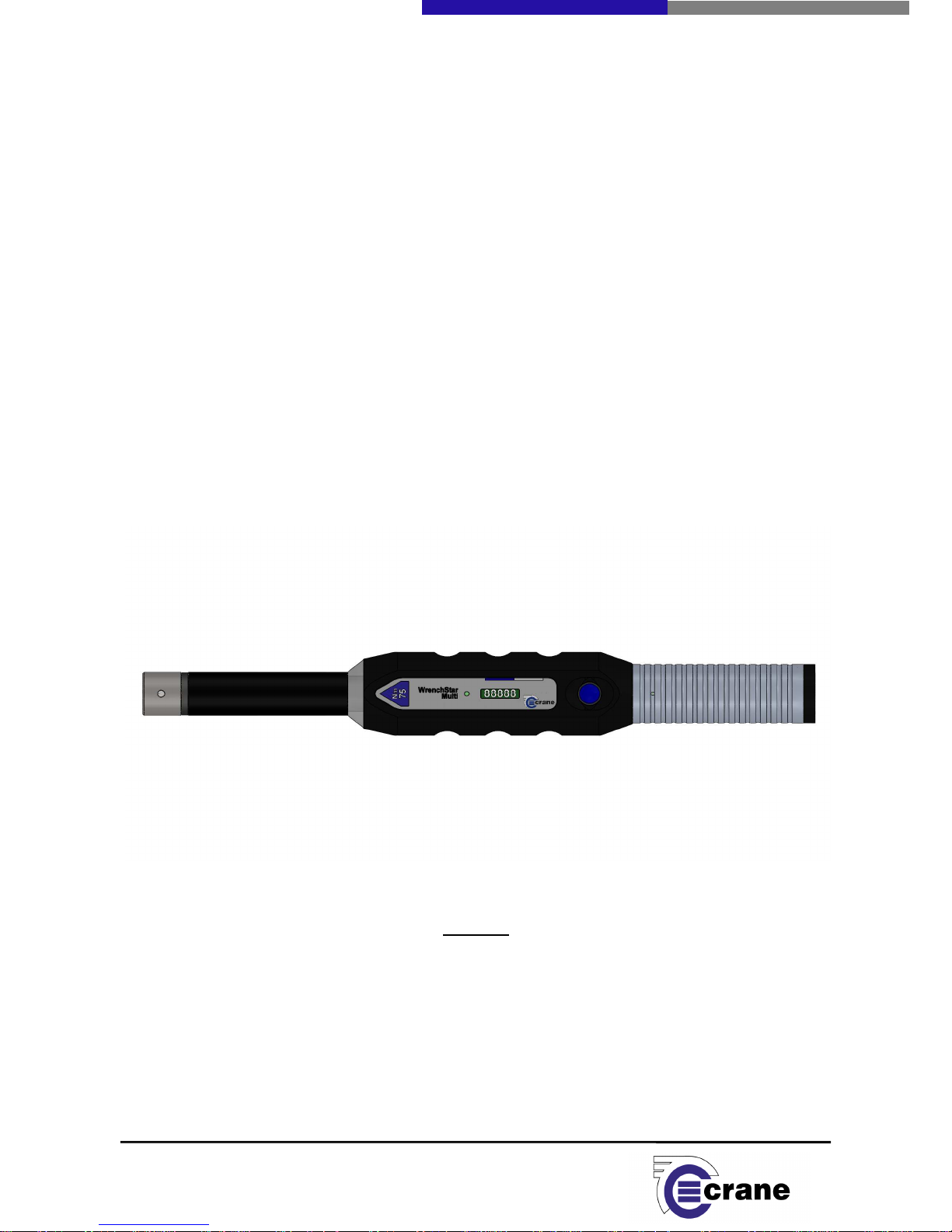
WRENCHSTAR MULTI
Manual 1230-01 Issue 1
Crane Electronics Ltd
NOTICE
ALL RIGHTS RESERVED. Reproduction of any part of this manual in any form whatsoever,
without the prior permission in writing from Crane Electronics Ltd is forbidden.
Copyright © by Crane Electronics Ltd

2
Crane Electronics Ltd
The force in torque management
Contents 2
CE Marking / Compliance 3
Product Disposal / About this Manual 4
Packing List / Spares /Care 5
Features and Dimensions / Overview WrenchStar Multi 6
Specifications 7
Main Functions and Features of WrenchStar Multi / Batteries 8
Warnings / Battery Warnings 9
Charging the WrenchStar Multi / WrenchStar Multi Button 10
Diagnostic Mode / Power on Sequence 11
Light Ring / ID Heads / Adapter Length Compensation 12
Battery Charge Status / Wrench Status LED / Vibrator 13
IQVu Setup with a WrenchStar Multi 14
Pairing the WrenchStar Multi 17
Loading Jobs 20
CONTENTS
Manufacturer:
Crane Electronics Ltd
Address:
3 Watling Drive
Sketchley Meadows
Hinckley
Leicestershire
LE10 3EY
Tel:
+44 (0)1455
Declares that this product has been assessed and complies with the requirements of
Directives.
Changes or modifications to the
could void
the user’s authority to operate the equipment.
This device complies with part 15 of the FCC rules. Operation is subject to the following two conditions: (1)
This device may not cause harmful interference, and (2) this device must accept any interference received,
including interference that may cause u
This equipment has been tested and found to comply with the limits for a Class
part 15 of the FCC Rules.
These limits are designed to provide reasonable protection against harmful
interference when the eq
uipment is operated in a
and can radiate radio frequency energy and, if not installed and used in accordance with the instruction
manual, may cause harmful interfe
rence to radio communications.
interference will not occur,
in a particular installa
radio or television reception, which can be determined by turning the equipment off and on, the user is
encourage
d to try to correct the interference by one or more of the following measures:
• Reorien
t or relocate the receiving antenna.
•
Increase the separation between the equipment
•
Connect the equipment into an outlet on a circuit different from that to
connected.
•
Consult the dealer or an experienced radio/TV technician to help.
CE MARKING
COMPLIANCE
3
25 14 88
WrenchStar Multi
not expressly approved by Crane Electronics Ltd
ndesired operation.
B
digital device, pursua
residential
environment. This equipment generates, uses,
However, there is
tion.
If this equipment does cause harmful interference to
and receiver.
which the receiver is
Crane Electronics Ltd
The force in torque management
the relevant CE
nt to
no guarantee that

4
Crane Electronics Ltd
The force in torque management
Applicable in the EU and other European Countries with separate collection systems
The symbol shown here and on the product means that the product is classed as Electrical or
Electronics Equipment and should not be disposed with normal commercial waste at the end of its
working life.
The Waste of Electrical and Electronics Equipment (WEEE) Directive (2002/96/EC) has been put in place to
recycle products using best available recovery and recycling techniques to minimise the impact on the
environment, treat any hazardous substances and avoid the increasing landfill.
For more detailed information about recycling of this product please contact your local authority or the
Company where you have purchased the product.
Battery pack disposal to take place in line with the AMENDED BATTERIES DIRECTIVE 2013/56/EU.
In Countries outside the EU:
If you wish to discard this product, please contact your local authorities and ask for the correct way of
disposal.
This manual covers the WrenchStar Multi communicating with an IQVu.
For information on torque transducers or PC software to be used in conjunction with IQVu, please refer to
Corresponding manuals accordingly.
Actual screen shots represented in this manual may differ slightly from those within the IQVu app
depending on version
For information on the operation of an IQVu please refer to its own manual.
Software Version of IQVu app =
Software Version of Torque Module = a) Main processor: 160_vx.x
b) RF processor: 162_vx.x
Software Version of TCI = a) Main processor: 184_vx.x
b) RF processor: 162_vx.x
Software Version of WSM = a) Main processor: 182_vx.x
b) RF processor: 161_vx.x
PRODUCT DISPOSAL
ABOUT THIS MANUAL

5
Crane Electronics Ltd
The force in torque management
The following items are supplied with the WrenchStar Multi dependant on model specification purchased.
1 x WrenchStar Multi
1 x User Manual (USB)
1 x Quick Start Guide (USB)
1 x Calibration Certificate
Please ensure all items are present and notify Crane Electronics Ltd immediately of any shortages.
DIN Adaptor
Battery Pack
Charging Cradle + Power Supply Unit
Charger
Cable
Operating temperature range -20 to +50 degrees C
Storage temperature range -20 to +50 degrees C
Humidity 10-75% non-condensing
IP Rating IP40 (indoor use only)
The WrenchStar Multi may be wiped clean with a soft cloth.
PACKING LIST
CARE AND STORAGE
SPARES
AND ACCESSORIES
6
Crane Electronics Ltd
The force in torque management
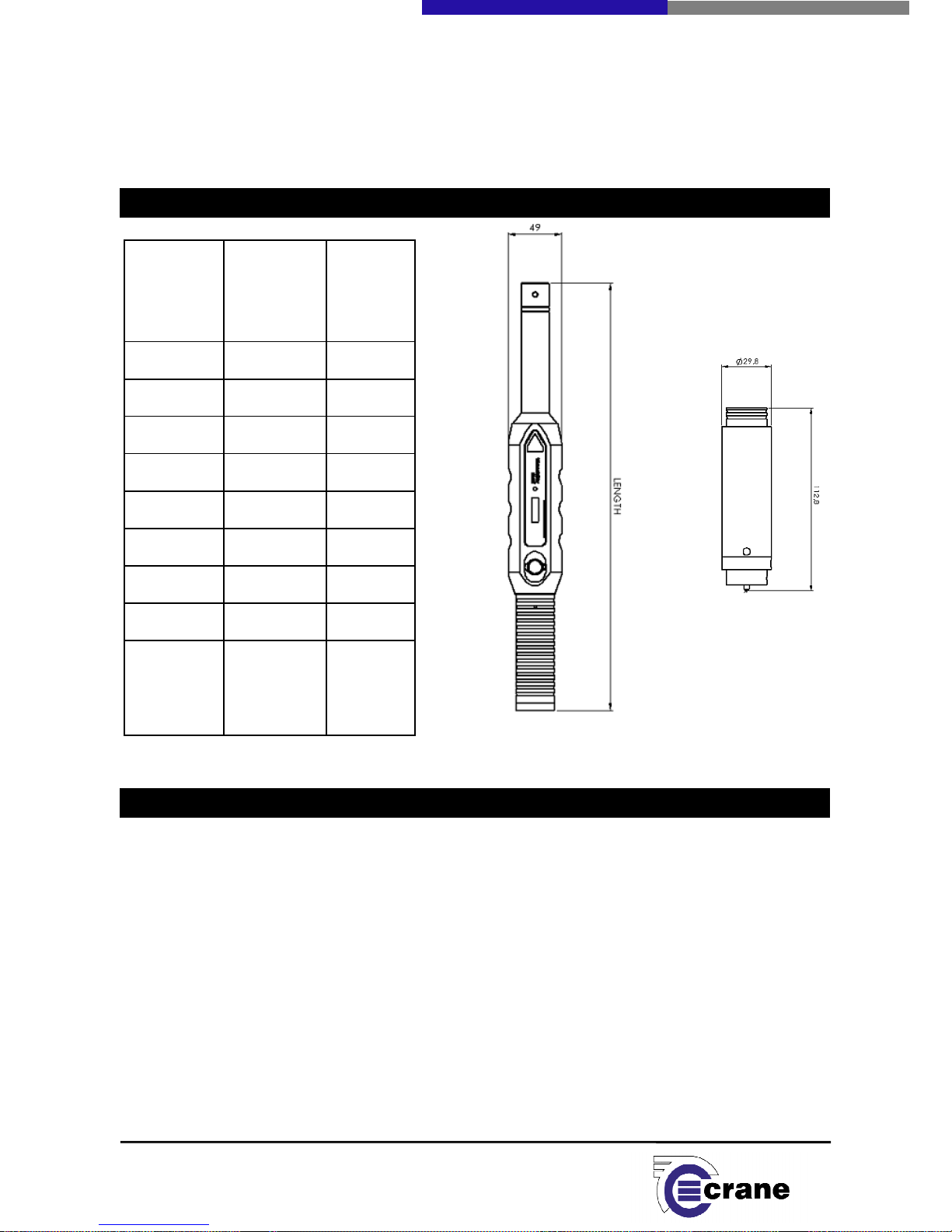
Size (Nm)
Length
(mm)
(excludes
adaptor) Mass (g)
10 380.3 832
25 380.3 839
75 395.3 926
180 613.3 1494
340 788.3 1956
500 866.5 3500
750 1178.3 5360
Battery
Pack
108.6
The WrenchStar Multi is a wireless production and quality audit wrench which works with the IQVu or TCI.
There is a variant that works with a cable connected to the IQVu. In this case there is no battery pack or RF.
The power comes from the IQVu and the Torque and Angle data are transmitted as digital signals along the
cable to the IQVu.
The WrenchStar Multi reads the Torque and Angle values in real time and converts them to digital values.
The WrenchStar Multi analyses the digital samples using measurement algorithms to calculate properties of
the fastening such as Peak. The WrenchStar Multi communicates the final fastening readings to an IQVu
using RF giving a range of approximately 10m*. If the WrenchStar Multi loses its link to the IQVu, then it
continues to work offline, storing up to 200 readings. It is very easy to pair, (associate the connection), of a
WrenchStar Multi with a particular IQVu.
The WrenchStar Multi contains its own power source which is a Lithium Ion battery pack.
* The RF range depends on the environment in which the WrenchStar Multi and IQVu are being used and
the figure quoted is for a relatively metal free work space with the IQVu in line of sight of the WrenchStar
FEATURES AND DIMENSIONS
OVERVIEW
– WRENCHSTAR MULTI

7
Crane Electronics Ltd
The force in torque management
Multi.
Physical Measurement: Bi-directional torque and angle, and pulse count
Measurement Modes: Peak Capture of highest torque value during the cycle
Move On Capture of move on point torque during auditing of tightened joint.
Yield Special measurement algorithm for use with joints being taken into
plastic region.
The Wrench supplies its Torque Range (span), PPR (for angle), serial number,
Calibration due date.
Reading Storage: The WrenchStar Multi can store up to 200 readings in offline mode.
LEDs: The WrenchStar Multi has a:
Charge LED used when charging battery pack.
Status LED
Light ring for fastening status.
Torque Measurement: Resolution to 0.006% of transducer span
Sampled every 60 micro-seconds (16,667) per second
Zero Stability: < 0.1% FSD / °C
Static Accuracy: +/-0.25% FSD
Angle Measurement: Sample every 1000 micro-seconds (1,000) per second
Frequency Response: A low pass Bessel Filter is employed for conditioning the transducer signal to
‘eliminate noise’ from the tool measurement
Selectable from 75Hz to 4608Hz
Readings: Readings are organised into subgroups.
Battery Pack: Re-chargeable Lithium Ion battery.
Capacity 2600mAh
3.7V
Weight 108.6g
Useable battery life of 10 hours with normal usage
Communication: Communicates with an IQVu using 2.400GHz RF
Warranty: 1 year manufacturer’s warranty
Display: OLED 32 x 128 pixels white
SPECIFICATIONS

8
Crane Electronics Ltd
The force in torque management
Serial number is on back.
The
The WrenchStar Multi unit has a battery pack that contains a Lithium Ion battery. From fully discharged the
unit will require up to a 4 hour charge to attain maximum capacity.
The full capacity of the battery is 2600mAh which yields approx. 10 hours of normal use.
When a WrenchStar Multi is placed in charging cradle, the charge indicator LED will illuminate with colour
according to the charge status.
MAIN FUNCTIONS AND FEATURES OF THE
WRENCHSTAR MULTI
Handle
Light Ring
Button
Status
LED
Charge
LED
BATTERIES
OLED
display
End Cap
Din adapter
Battery pack

9
Crane Electronics Ltd
The force in torque management
Charge Indicator LED Status
Red = Charging
Green = Charged
Off = no charging
Maintain unit with care. Keep unit clean for better and safer performance.
Changes or modifications to the WrenchStar Multi not expressly approved by Crane Electronics
Ltd could void the user’s authority to operate the equipment.
Always operate WrenchStar Multi with approved battery pack.
Always operate, inspect and maintain this unit in accordance with all regulations (local, state,
federal and country) that may apply.
Do not remove any labels.
Always use Personal Protective Equipment appropriate to the tool used and material worked.
Keep body stance balanced and firm. Do not overreach when operating with the tool. Anticipate
and be alert for sudden changes in motion, reaction torque, or forces during the operation.
Ensure work pieces are secure. Use clamps or vices to hold work pieces whenever possible.
Never use a damaged or malfunctioning tool or accessory with this unit.
Follow instructions for changing accessories.
Do not operate this product in explosive atmospheres, such as in the presence of flammable
liquids, gases or dust.
This unit contains no user serviceable parts. Only qualified service personnel should replace or fit
parts.
Charge the WrenchStar Multi before use.
Only charge the WrenchStar Multi in specified cradle.
Keep battery pack terminals clean.
Always store the battery pack in a dry place.
Do not short circuit the battery pack.
Do not disassemble the battery pack.
Do not expose the battery pack to high temperature.
WARNINGS
BATTERY WARNINGS

10
Crane Electronics Ltd
The force in torque management
The wrench can be charged by inserting into the charging cradle.
Note: alternative charging methods may become available in the future.
The WrenchStar Multi will monitor its battery level. If the battery level goes below 10% the status LED will
flash blue. If the status LED starts flashing it is recommended that the readings are immediately finished and
the WrenchStar Multi taken back to the IQVu to upload any remaining readings. The WrenchStar Multi
should be fully charged in a cradle before using. If the level goes to 0% the WrenchStar Multi will switch
OFF.
Charger voltage is 5V.
The WrenchStar Multi button has several functions:
• When the WrenchStar Multi is OFF pressing the button for less than 1s will turn the WrenchStar
Multi ON.
• When the WrenchStar Multi is ON and the button is pressed for approx. 2s the WrenchStar Multi will
go into pairing mode and the status LED will change to purple.
• If the WrenchStar Multi is in pairing mode pressing the button will take the WrenchStar Multi back to
normal RF mode and the status LED will change to blue.
• If the WrenchStar Multi is ON and the button is held for more than 5s then the WrenchStar Multi will
switch OFF.
The WrenchStar Multi will switch OFF after 10 minutes of no activity. It can be turned back ON with a press
of the button. No activity means no torque messages from the IQVu and no torque pulled.
CHARGING THE WRENCHSTAR MULTI
WRENCHSTAR MULTI BUTTON

11
Crane Electronics Ltd
The force in torque management
During switch ON if press blue button 3 x in quick succession it will go into Diagnostic Mode:The following information will be shown on the display. The number of taps is the number of taps on the blue
button that will advance the display onto the next diagnostic function.
• Raw ADC from gauges 1 and 2.
1 Tap
• Connected ADC
1 Tap
• Zero offset
2 Tap
• Gyro Type
2 Tap
• Torque Track
2 Tap
• Angle Track
2 Tap
• Battery % level
2 Tap
• Adapter ID and length
2 Tap
• Testing on display
Status LED cycle Red, Green, Blue
2 Tap
• Testing Light Ring cycle Red, Green, Amber
2 Tap
• Testing
• Light Ring cycle Red, Green, Amber
2 Tap
• Testing
• Vibrator turning on and off
2 Tap
Number of over torques and largest over torque
2 Tap
Start
The following information will be displayed when switch ON WrenchStar Multi:
- Crane logo
- s/w version 182-vx.x
161-vx.x
- Span in Nm
- Recal Date DD/MM/YY
- Battery level %
DIAGNOSTIC MODE
POWER ON SEQUENCE

12
Crane Electronics Ltd
The force in torque management
- WAIT if no job loaded. Else. Measure Mode (Peak, MoveOn, Yield)
Number of readings to go.
To turn OFF hold Blue Button until status LED turns off, then release the button.
To turn ON press Blue Button.
During and after fastening the light ring will indicate the primary parameter status, which will be
torque except for Peak Angle Control, in which case it will be angle.
• Amber = LO
• Green = OK
• Red = HI
If the secondary parameter goes HI then light ring will go Red regardless of state of the primary
parameter.
If MoveOn or Yield are not detected and torque was LO or OK then will get amber flash sequence
(dash dot dot), otherwise if torque was HI then will get red flash sequence (dash dot dot).
The light ring will start indicating the status as soon as torque goes above threshold.
When a new job is received the light ring will cycle twice through sequence amber, green, red to
indicate job has been received and loaded. It will do the same when power up and the job is already
loaded.
When a job is complete the light ring will continuously cycle through sequence amber, green, red
until data is completely removed.
• The WrenchStar Multi will work with the Crane 1-Touch ID Head recognition system, the Crane 1-
Touch system allows the wrench to compensate for special head designs that do not use the
standard insert head dimensions.
• The Crane 1-Touch Heads can be programmed with an ID from 1 through to 126, if there is no ID
then the WrenchStar Multi will not use the ID system and treat the head as a standard insert head,
with a critical compensation length of Zero.
• The 1-Touch ID heads can be programmed with a compensation length, these lengths can be from 0
to 200 mm. When the wrench recognises that there is an ID Head present, it will automatically
compensate the torque by the critical length programmed into the head.
• The 1-Touch ID Heads can be programmed up to 4 times, therefore if the compensation value needs
to be updated, this can be done up to 3 times. This programming is done by Crane Electronics.
• Below is a diagram of how to calculate the critical length for an ID Head.
LIGHT RING
ID HEADS / ADAPTER LENGTH COMPENSATION

13
Crane Electronics Ltd
The force in torque management
Battery Charge Status:
Battery charge status will have 2 colours:
• Red = Charging
• Green = Charged
• No LED = No charging source present and running off battery power.
Battery Charge Status will be available even when the WrenchStar Multi is off. It will only be
viewable when connected to a charging source.
Wrench Status LED:
• Black = Wrench powered Off
• Red = On and not paired
• Magenta (purple) = Ready to pair
• Blue = Paired and RF in range
• Amber = Paired, received job and not in range
• Green = Paired, received job and in range of receiver
Flashing between blue and yellow indicates low battery
BATTERY CHARGE STATUS
WRENCH STATUS LED

The strong
vibrator will be turned on when primary status becomes OK or either primary or
secondary status becomes HI.
Before using an IQVu
with the WrenchStar Multi
Turn the IQVu on.
Press and release the Power
The IQVu is configured with SOTI software in order to provide the most
Select the Crane IQVu icon, the app will load and a Crane splash screen will be displayed before entering
the login screen.
Select the relevant
user icon and a virtual keypad will be displayed.
IQVu SETUP WITH A WRENCHSTAR MULTI
VIBRATOR
14
make sure the WrenchStar Multi is
charged.
button on top of the IQVu.
secure environment.
Enter the
password and click OK.
Crane Electronics Ltd
The force in torque management

15
Crane Electronics Ltd
The force in torque management
After logging in the user is taken to the Home Page menu.
To review more icons simply swipe across the screen and select ‘settings’.
Use the right arrow to select ‘Settings: 4/9 Connection’.

Select ‘GET DATA’
. Fields will be filled with default information.
Select the ‘RF Address’ field.
Change the RF
between 0 and 65535.
Do not keep the default address that appears.
Select ‘Power’ field’.
The Power level can be 0
set to 3 then the range will be at its
maximum
0 approx 1m
1 approx 4m
2 approx 7m
3 approx 10m
Select ‘Channel’. Set the (
frequency
If there is an interfering source then you can change the channel.
After editing select ‘SET DATA’.
Select
on keypad to return to full screen.
When WrenchStar Multi
are paired with the IQVu,
can all work together.
Therefore if these
stop working and a
previously paired WrenchStar Multi
**The IQVu should be re-
booted after set up of a new RF address and channel.
button. Select ‘Power off’ then
‘Reboot
Login and select ‘Settings’ following previous instructions.
Use
the right arrow to go to ‘Settings: 8/9 Readings’
Select Home icon. S
wipe across the
At this stage there is no
WrenchStar
Switch on the WrenchStar Multi.
Press
and the
status LED will change to red.
PAIRING THE WRENCHSTAR MULTI
16
address to a unique one for that IQVu
and enter a value
– 3 and affects the transmission
range
. If power level is set to 0 then the
range
) channel between 0 and 79. Try and make
this unique for each IQVu.
they will be given the same RF Setup as the IQVu so they
settings are changed on the IQVu, then all previous pairings will
would need to be re-
paired with the IQVu.
**
.
screen and select ‘Transducers’.
Multi paired.
Blue Button for less than 1s and the
WrenchStar Multi
Crane Electronics Ltd
The force in torque management
If the Power level is
will be at its shortest.
Press and hold power
will turn ON

17
Crane Electronics Ltd
The force in torque management
Press button for approx. 2s until the status LED changes to purple. The WrenchStar Multi is now ready to be
paired. Place the WrenchStar Multi close to within 30cm of the IQVu as the pairing process occurs over a
short distance.
Select and hold one of the rows on the transducer screen, for example Row *RF1. An ‘Actions’ box will be
displayed.
Select ‘Pair’ and, if the pairing is successful, within a few seconds you will see the following screen.
The WrenchStar Multi status LED will change from purple to blue. The WrenchStar Multi will now remember
it’s pairing even if it’s turned off.
If pairing is not successful change the channel and repeat the pairing process.
You will see a row of yellow information. It will give:
• The serial number of the WrenchStar Multi it’s connected to.
• The Type ‘3’ indicates it is a WrenchStar Multi.
• The span of the WrenchStar Multi which is used in jobs to see if the WrenchStar Multi is capable of
performing a certain fastening specification./ or is used to confirm if the WrenchStar Multi is within
the range of the fastening specification.
• Port – The IQVu in the future can potentially talk with up to 6 WrenchStar Multi simultaneously. At
present only one RF WrenchStar Multi can communicate to the IQVu.
• PPR is from the attached transducer and is a statement of the angle resolution.

If you select
the paired transducer the text will turn to green to show
of the WrenchStar Multi will be
displayed
charge the battery in the WrenchStar Multi.
If you select ‘Dongle info’ from the
‘Actions’ box the following RF
Select ‘OK’ to return to the ‘Transducers’ screen.
Select icon.
Once the WrenchStar Multi
is paired and selected,
‘Check’ or ‘Jobs
’ from the home screen
Multi supports Peak (plus angle),
Move
To create a new Job select
the “Add Job” icon in
transducer selection, followed by requiring the user to select a measurement mode.
swipe to the lef
t or press the right arrow
LOADING JOBS
18
there is
a connection. The battery level
. If the battery level is below 10%, then
you should immediatel
information
will be displayed.
you can enter a mea
surement screen either through
. You can set up the measurement mode. At
pr
On and Yield.
the bottom corner of the screen.
The IQVu will
With the mode selected
and configure the settings as required.
Crane Electronics Ltd
The force in torque management
y
esent the WrenchStar
prompt for a

Select to save Job.
When you enter the measurement screen, the job will be
WrenchStar Multi can store
one subgroup of one job and up
When the job is transferred,
the WrenchStar Multi
At this stage you can start tak
ing measurements with the
left. The WrenchStar Multi
will locally measure the torque every
It will analyse the measurement with the selected algorithm.
As the measurement is taken, the
WrenchStar Multi li
19
transferred to the WrenchStar Multi
to 200 readings for that subgroup.
light ri
ng will flash amber, green then red twice
WrenchStar Multi.
It will tell you how many
20 micro seconds
and the angle every 1ms.
ght ring will
show the status of the measurement. The
Crane Electronics Ltd
The force in torque management
. The
.
readings

20
Crane Electronics Ltd
The force in torque management
primary measurement (torque unless angle control) will display:
Yellow (amber) =Threshold < Value < LSL
Green = LSL < Value < USL
Red (user should stop pulling if they see Red) = USL < Value
If the Secondary value goes greater than its USL you will see a Red light on the WrenchStar Multi to warn
the user to stop.
At the end of a measurement, until the next measurement starts, the WrenchStar Multi will display the
primary measurement status for that joint.
In the case of a MoveOn or Yield not being found the Light Ring will flash (long flash followed by 2 short
flashes) amber if the torque reading remains below the USL and flash red if the final torque reading is above
the USL.
The WrenchStar Multi is constantly being polled by the IQVu for readings (every 0.5s). If the WrenchStar
Multi goes out of range it can continue to take readings, which it will store. Once the WrenchStar Multi is in
range of IQVu, the readings will be polled out of the WrenchStar Multi, oldest first.
If the WrenchStar Multi completes the subgroup of the job it will flash amber, green then red twice. When
this happens you should take the WrenchStar Multi back to the IQVu so any remaining readings can be
uploaded. If required, you can then download the next subgroup.
IQVu check is assumed to be a job subgroup with 200 readings.
The IQVu will show the readings it gathers from the WrenchStar Multi in the standard way. The readings will
have their status colour coded as usual. The reading count will show how many readings have been
retrieved.
Note: - no traces are stored or can be retrieved from the WrenchStar Multi.
The following screens show examples of readings gathered by IQVu from the WrenchStar Multi using
different measurement modes:

21
Crane Electronics Ltd
The force in torque management
Peak plus Angle
MoveOn
Yield

22
Crane Electronics Ltd
The force in torque management
 Loading...