

Crane Electronics Ltd
The force in torque management
Crane Electronics Ltd
Watling Drive
Sketchley Meadows
Hinckley LE10 3EY
Tel: +44(0) 1455 25
www.crane
Operator’s Manual
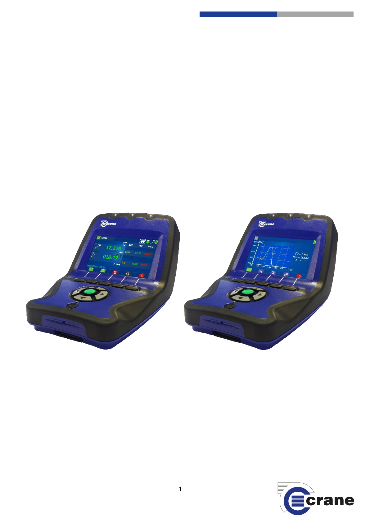
TorqueStar Plus / Pro Data Collector
Manual 1293-01 Issue 1
Crane Electronics Ltd
ALL RIGHTS RESERVED. Reproduction of any part of this manual in any form whatsoever,
14 88
-electronics.com
Notice
without the prior permission in writing from Crane Electronics Ltd is forbidden.
Copyright © April 2019 by Crane Electronics Ltd.
1

Crane Electronics Ltd
The force in torque management
Crane Electronics Ltd
Watling Drive
Sketchley Meadows
Hinckley LE10 3EY
Tel: +44(0) 1455 25
www.crane
Contents 2
CONTENTS
CE Marking & Compliance 3
Product Disposal & About this Manual 4
Packing List 5
Spares & Accessories 5
Features & Dimensions 6
Specifications 7
Hardware 8
Technical Features 8
Icons - TorqueStar Plus / Pro 9
Start Up 11
Inputs 14
Charging your TorqueStar 14
Connecting a Transducer 15
Manual Transducer Set-up 15
Settings 17
Power Settings 18
Date & Time Settings 18
Language Settings 19
Misc. Torque Settings 20
AutoPrint Settings 20
Unlocking 21
Pro Settings 21
Settings Measurement 22
Check Measurement Screen 23
Measurement Options 25
Reading List 27
Reading Trace 28
Statistics 29
Deletion 29
Warning Screens 30
TorqueStar Pro Features
Virtual keyboard 32
Login Screen 32
Communication with OMS Lite 33
Home Screen (Pro Only) 33
Jobs 34
Add Jobs & Setup 34
Job Measurement Screen 37
Job Reading List Screen 38
Job Statistics 38
Rounds 39
Add Rounds & Setup 39
14 88
-electronics.com
2
Crane Electronics Ltd
The force in torque management
Crane Electronics Ltd
Watling Drive
Sketchley Meadows
Hinckley LE10 3EY
Tel: +44(0) 1455 25
www.crane
CE MARKING
COMPLIANCE
Changes or modifications to the TorqueStar range not expressly approved by Crane Electronics Ltd could void
Manufacturer: Crane Electronics Ltd
Address: 3 Watling Drive
Sketchley Meadows
Hinckley
Leicestershire
LE10 3EY
Tel: +44 (0)1455 25 14 88
Declares that the TorqueStar range has been assessed and complies with the requirements of the relevant CE
Directives.
the user’s authority to operate the equipment.
This device complies with part 15 of the FCC rules. Operation is subject to the following two conditions: (1) this
device may not cause harmful interference, and (2) this device must accept any interference received,
including interference that may cause undesired operation.
NOTE: This equipment has been tested and found to comply with the limits for a Class B digital device,
pursuant to part 15 of the FCC Rules. These limits are designed to provide reasonable protection against
harmful interference in a residential environment. This equipment generates, uses, and can radiate radio
frequency energy and, if not installed and used in accordance with the instructions, may cause harmful
interference to radio communications. However, there is no guarantee that interference will not occur in
particular installations. If this equipment does cause harmful interference to radio or television reception
which can be determined by turning the equipment off and on, the user is encouraged to try to correct the
interference by one or more of the following measures:
• Reorient or relocate the receiving antenna.
• Increase the separation between the equipment and receiver.
• Connect the equipment into an outlet on a circuit different from that to which the receiver is connected.
• Consult the dealer or an experienced radio/TV technician for help.
14 88
-electronics.com
3
Crane Electronics Ltd
The force in torque management
Crane Electronics Ltd
Watling Drive
Sketchley Meadows
Hinckley LE10 3EY
Tel: +44(0) 1455 25
www.crane
PRODUCT DISPOSAL
ABOUT THIS MANUAL
Applicable in the EU and other European Countries with separate collection systems
The symbol shown here and on the product means that the product is classed as Electrical or
Electronics Equipment and should not be disposed with normal commercial waste at the end
of its working life.
The Waste of Electrical and Electronics Equipment (WEEE) Directive (2012/19/EU) has been put in place to
recycle products using best available recovery and recycling techniques to minimise the impact on the
environment, treat any hazardous substances and avoid the increasing landfill.
To enable this product to be disposed of properly i.e. cradle to grave, Crane Electronics is willing to accept the
return of your product (at your cost) for recycling or alternatively, for more detailed information about
recycling of this product please contact your local authority or the Distributor / Company where you have
purchased the product.
Battery disposal to take place in line with the AMENDED BATTERIES DIRECTIVE 2013/56/EU. Batteries must
not go to landfill. Check with local legislation.
Crane Electronics declares that this product does not contain any of the 191 Substances of Very High Concern
(SVHC’s) identified in the REACH Regulation in used articles make-up.
In Countries outside the EU:
If you wish to discard this product, please contact your local authority and ask for the correct way of disposal.
Signed for & on behalf of Crane Electronics Ltd.
Name: B. M. Etter
Title: Safety & Environmental Advisor Signature of Issuer:
This manual covers the TorqueStar Plus / Pro versions, working with our range of torque transducers and
digital torque wrenches.
Actual screen shots represented in this manual may differ slightly from those on the actual
TorqueStar unit, depending on the version.
For information on the operation of one of our digital torque wrenches or torque
transducers, please refer to their own manuals.
Software version: TorqueStar Plus / Pro
14 88
-electronics.com
4
Crane Electronics Ltd
The force in torque management
Crane Electronics Ltd
Watling Drive
Sketchley Meadows
Hinckley LE10 3EY
Tel: +44(0) 1455 25
www.crane
PACKING LIST
SPARES AND ACCESSORIES (with Product Code)
The following Items are supplied with the TorqueStar Pro dependent on model specification purchased.
1 x TorqueStar Plus / Pro
1 x Calibration Certificate
1 x Quick Start Guide (with QR code link to operator’s manual)
1 x 5V PSU Power Adapter
1 x USB to Micro USB connection cable
1 x USB Flash Drive
1 x Carry Lanyard
1 x Type A–A USB Cable (Pro Only)
All contents are supplied in a hard plastic case with foam insert.
Please ensure all items are present and notify Crane Electronics Ltd immediately of any shortages.
Additional Batteries 080159
5V PSU Power Adapter TSXXA – 0000 - CRPXXX
External battery charger TSXXA – 0000 - CRCXXX
USB to Micro USB connection cable 090301
Carry Lanyard 110385
Protective Case TSXXA – 0000 - CRTXXX
USB Flash Drive POA
Type A-A USB Cable POA
14 88
-electronics.com
5
Crane Electronics Ltd
The force in torque management
Crane Electronics Ltd
Watling Drive
Sketchley Meadows
Hinckley LE10 3EY
Tel: +44(0) 1455 25
www.crane
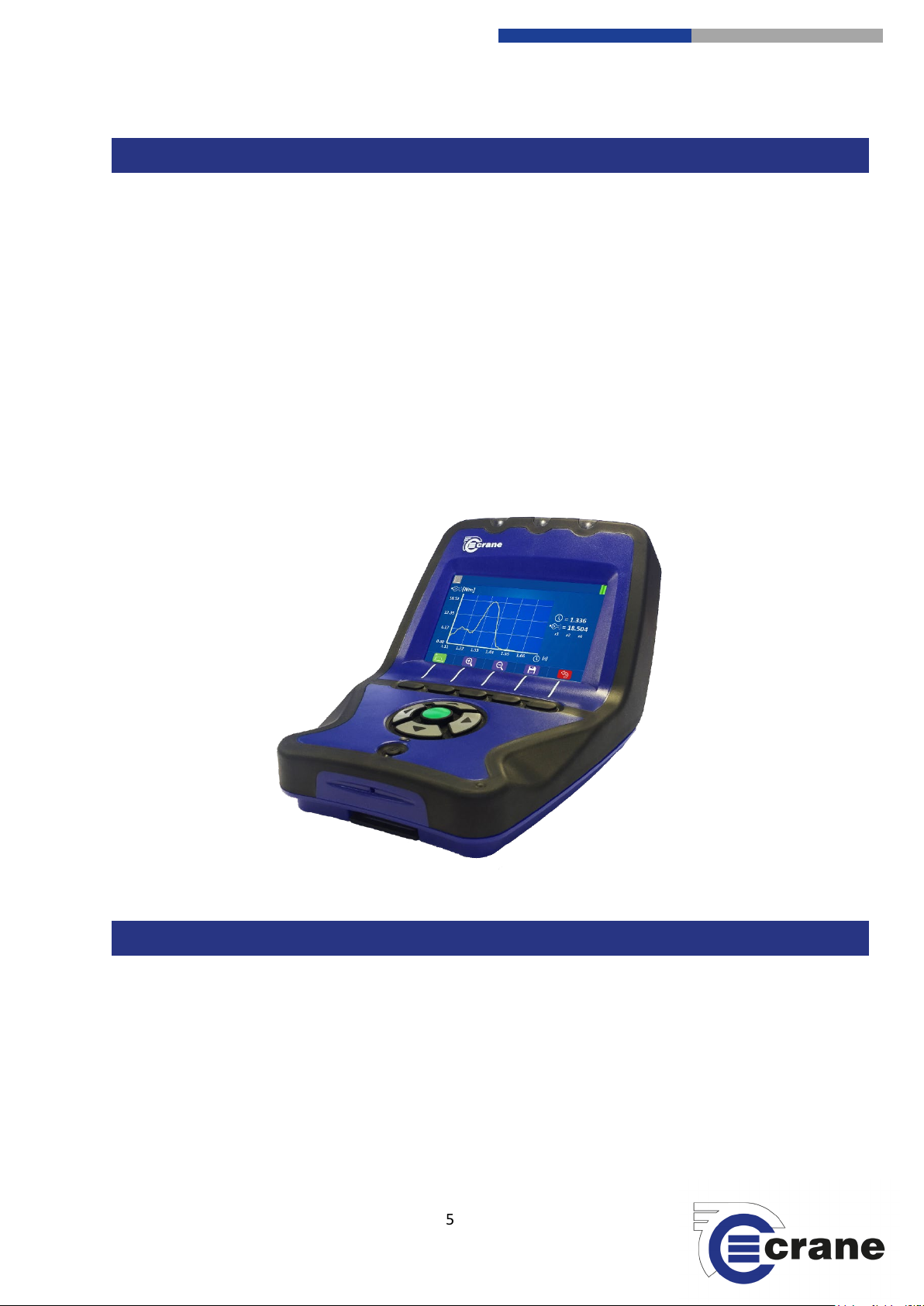
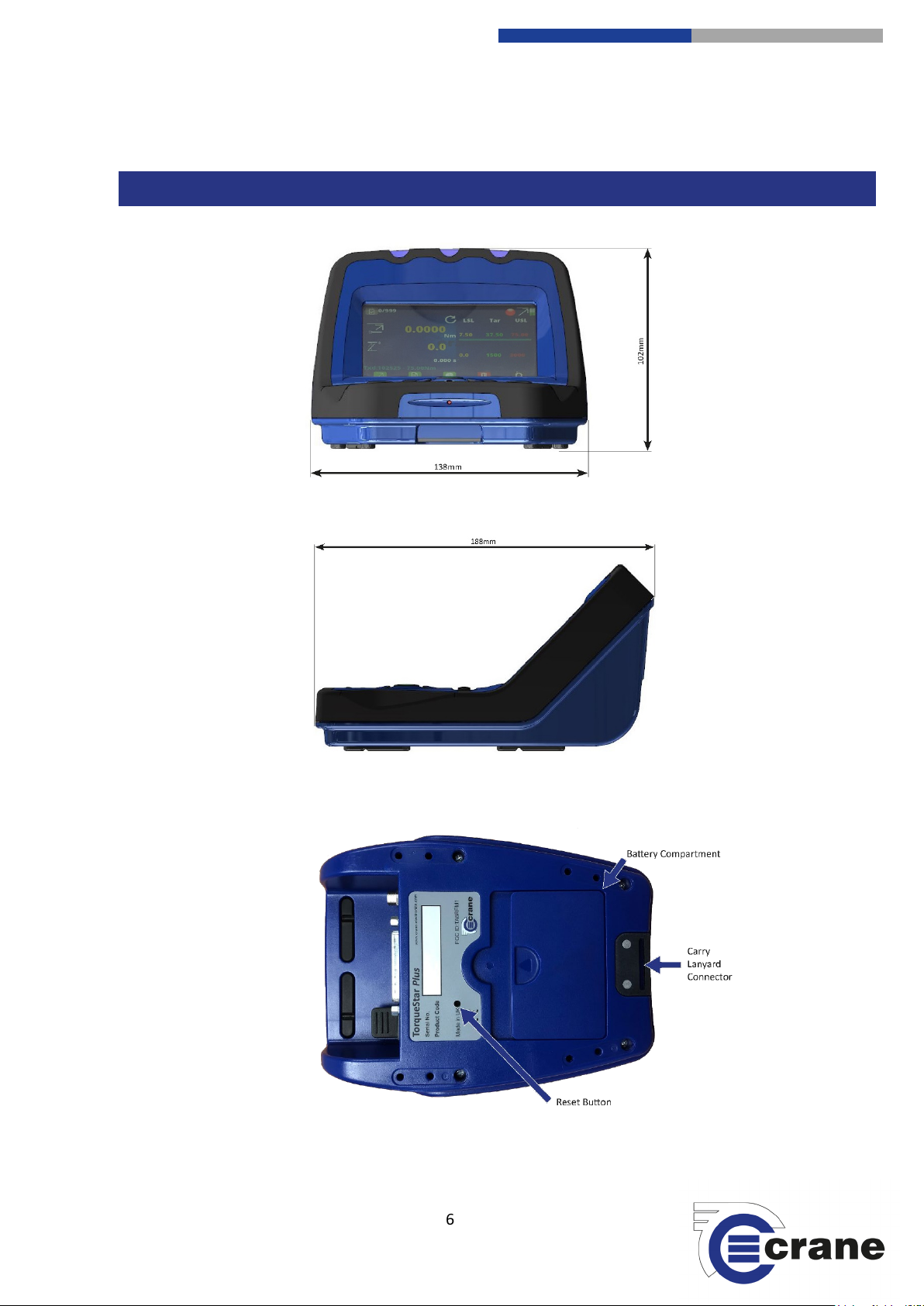
FEATURES AND DIMENSIONS
14 88
-electronics.com
6

Crane Electronics Ltd
The force in torque management
Crane Electronics Ltd
Watling Drive
Sketchley Meadows
Hinckley LE10 3EY
Tel: +44(0) 1455 25
www.crane
SPECIFICATIONS
Measurement Modes:
Track – Real time torque
Peak – Capture of the highest torque
Pulse – Special measurement algorithm for use with impulse tools, incorporating pulse count
Click – Special measurement algorithm for use with click tools
Force – Capture of peak force during cycle
Audit – Special measurement algorithm that measures torque after joint moves a certain angle
Yield – Special measurement algorithm that measures torque after joint goes into yield (Pro only)
MoveOn – Special measurement algorithm that measures torque of previously tightened joint (Pro only)
Retightened – Special measurement algorithm that untightens a fastened joint and retightens to the same
angle (Pro only)
Measurement Units:
Torque – Nm, lbft, lbin, MNm, Ncm, kgcm, kgm, kNm, klbft, Nmm, ozin
Force – kg, kkg, lb, klb, N, kN
Physical Measurements:
Auto Bi-directional torque; angle*; pulse count; RPM in track mode*; cycle time duration (*when using rotary
transducer).
Compatible Input Devices:
IS, UTA, and Multi, including WrenchStar Multi, cable products compatible, analogue or digital.
Plug & Play Transducer Data:
Auto ID of all Crane UTA/Multi products. The following information is read from the chip in the transducer -
torque range, angle encoder data, serial number, calibration due date.
Data Storage:
999 readings in ‘Check’ and 20,000 readings in ‘Jobs’.
Basic Statistics:
Count, range, mean, min, max, standard deviation.
Advanced Statistics:
Cm, Cmk, Cp, Cpk
Auto Print / Data Output:
Easy selectable output to AutoPrint or CSV. Interface to simple PC package that outputs the print data to an
Excel spreadsheet.
Cycle Status Indication:
Audible buzzer and LED HI/OK/LO torque status. User definable.
Operating Languages:
English, Chinese, Czech, French, German, Italian, Spanish, Swedish, Polish, Portuguese, Turkish
14 88
-electronics.com
7

Crane Electronics Ltd
The force in torque management
Crane Electronics Ltd
Watling Drive
Sketchley Meadows
Hinckley LE10 3EY
Tel: +44(0) 1455 25
www.crane
HARDWARE
TECHNICAL FEATURES
Construction:
High strength injection moulding. Protective rubberised trim to alleviate secondary damage. Soft rubber trim
surrounding tough internal chassis. Can survive 1.8m drop.
Display:
Colour Backlit 4”screen (86mm x 52mm)
Keypad:
Easy clean keypad. 11 Keys including 5 function keys, 5 soft directional keys and on/off key.
Power:
Universal 5V charger or USB charger.
Power Management:
User selectable auto power-off: Between 0 - 200 minutes. Screen contrast and brightness adjustment.
Battery Pack:
Lithium Ion - User swappable. Charge time: 3 hours with appropriate charger current. Chargeable via USB or
5V charger. Typical operating time: 4 hours continuous use.
Input/output ports:
25 pin ‘D’ type transducer port (female) (digital or analogue).
Micro USB (2.0) for power and export.
Standard USB type A (on-the-go).
5V DC power port for use with mains power DC charger.
Zero Stability:
<± 0.01% FSD/ °C.
Static Accuracy:
± 0.25% FSD of connected transducer.
Operating Environment:
Temperature: -20 to +50 °C.
Humidity 10-75% non-condensing.
Ingress protection rating: IP45
.
Torque Measurement
Display to 5 significant figures. Sample every 20 micro seconds.
Angle Measurement:
Quadrature phase input. Display angle to 0.1 degrees, Sample every 1000 micro seconds.
Warranty:
12 months parts and labour against faulty workmanship or materials.
14 88
-electronics.com
8
Crane Electronics Ltd
The force in torque management
Crane Electronics Ltd
Watling Drive
Sketchley Meadows
Hinckley LE10 3EY
Tel: +44(0) 1455 25
www.crane
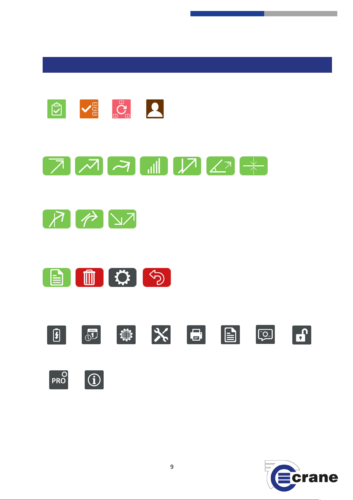
Peak
Click
Track
Pulse
Audit
ICONS – TorqueStar Plus / Pro
Power
Date / Time
Language
Misc.
Torq u e
AutoPrint
Readings
Peak Angle
Force
MoveOn
Yield
Re-tighten
Check
Jobs
Rounds
Users
Readings
Delete
Settings
Back
Comments
Unlock
Pro Only
Splash
screen
Functions:
Measurement Modes:
Pro only:
Measurement Functions:
Settings:
14 88
-electronics.com
9
Crane Electronics Ltd
The force in torque management
Crane Electronics Ltd
Watling Drive
Sketchley Meadows
Hinckley LE10 3EY
Tel: +44(0) 1455 25
www.crane
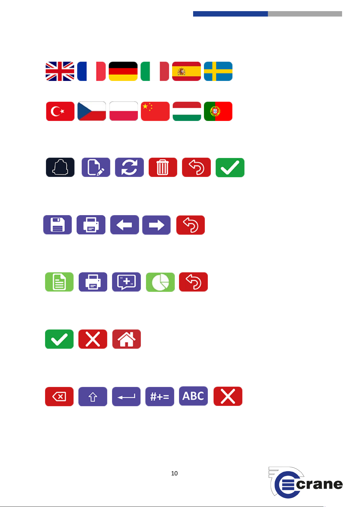
Languages:
Statistics
Swap Primary &
Secondary
Save
Print
English
French
German
Italian
Swedish
Spanish
Portuguese
Hungarian
Chinese
Polish
Czech
Turkish
Transducer
Edit
Refresh
Delete
Back
Back
Readings
Print
Add
Comment
Back
Accept /
Yes
Cancel /
No
Home
Accept
Erase
Shift Key
Enter
Numbers /
Symbols
Text
Cancel /
No
Transducer Screen:
Statistics screen:
Reading List Screen:
General:
Keyboard:
14 88
-electronics.com
10
Crane Electronics Ltd
The force in torque management
Crane Electronics Ltd
Watling Drive
Sketchley Meadows
Hinckley LE10 3EY
Tel: +44(0) 1455 25
www.crane
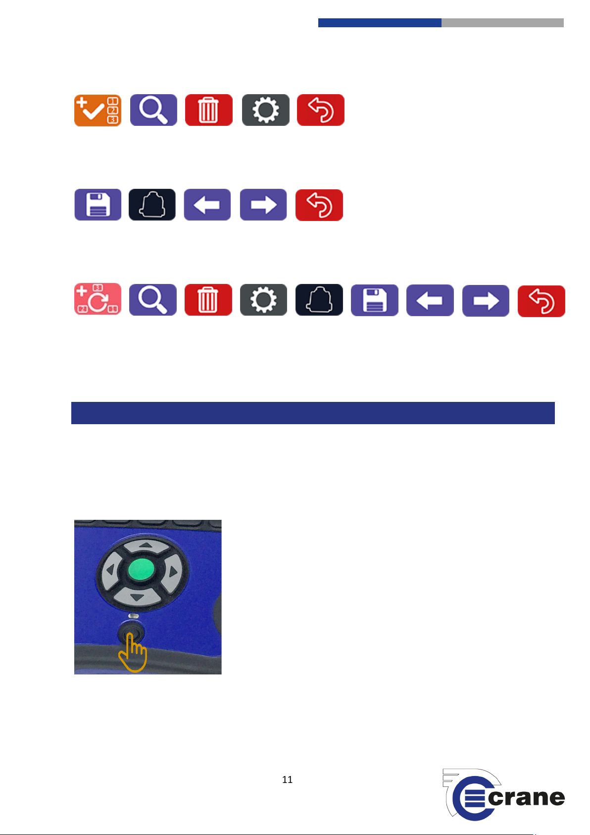
Job List Screen (Pro only):
Save
Search
Delete
Add Job
START UP
Job Setup
Search
Delete
Transducer
Previous
Setting
Save
Further
Setting
Back
Add Rounds
Round
Setup
Transducer
Back
Previous
Setting
Further
Setting
Back
Job Edit (Pro only):
Rounds List & Edit Screens (Pro only):
Turning on your TorqueStar:
Turn on the TorqueStar by pressing the on/off button situated below the arrowed keypad.
Pressing this button whilst the TorqueStar is on will turn it off.
14 88
-electronics.com
11
Crane Electronics Ltd
The force in torque management
Crane Electronics Ltd
Watling Drive
Sketchley Meadows
Hinckley LE10 3EY
Tel: +44(0) 1455 25
www.crane
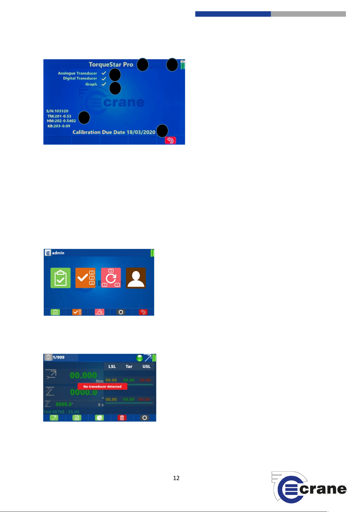
The first screen you will see is as below.
1
2 3 4
5
6
1) Model (Plus or Pro)
2) Transducers available
3) Serial Number S/N, Torque Module latest
release, HMI Module latest release,
Keyboard latest release
4) Advised calibration due date for this data
collector
5) Features unlocked
6) Battery Status
It confirms what version of TorqueStar you have. In the screenshot above it tells you that you can use
Analogue and Digital Transducers only. RF Transducers can only be used with the TorqueStar Pro (future
option).
In the top right-hand corner it will show the current level of battery life and whether it is being charged or not.
Charging is denoted by a lightning flash.
The serial number of the model you have is displayed, along with the latest software release for the Torque
Module, HMI Module and Keyboard. The opening screen also shows the calibration due date of the model you
have.
If you press the green button or wait the TorqueStar will load its settings for a few seconds and the Home
screen will be displayed.
You will notice there are 5 aligned keys with icons displayed
along the bottom of the screen. These are soft function keys
and their action depends on the icon displayed. F1 is the left
hand function key, then F2, F3, F4, and F5 is the right hand
function key.
For the TorqueStar Plus, only Check and Settings icons on the
lower part of the display are active. The Jobs and Rounds icons
will be greyed out as they are only active on the TorqueStar Pro.
Press the Check (F1) icon or use Left and Right arrow keys to highlight required function then press green key.
If no transducer is plugged in then this screen will appear.
Please connect a transducer. See ‘Connecting a Transducer’
set up.
14 88
-electronics.com
12
Crane Electronics Ltd
The force in torque management
Crane Electronics Ltd
Watling Drive
Sketchley Meadows
Hinckley LE10 3EY
Tel: +44(0) 1455 25
www.crane
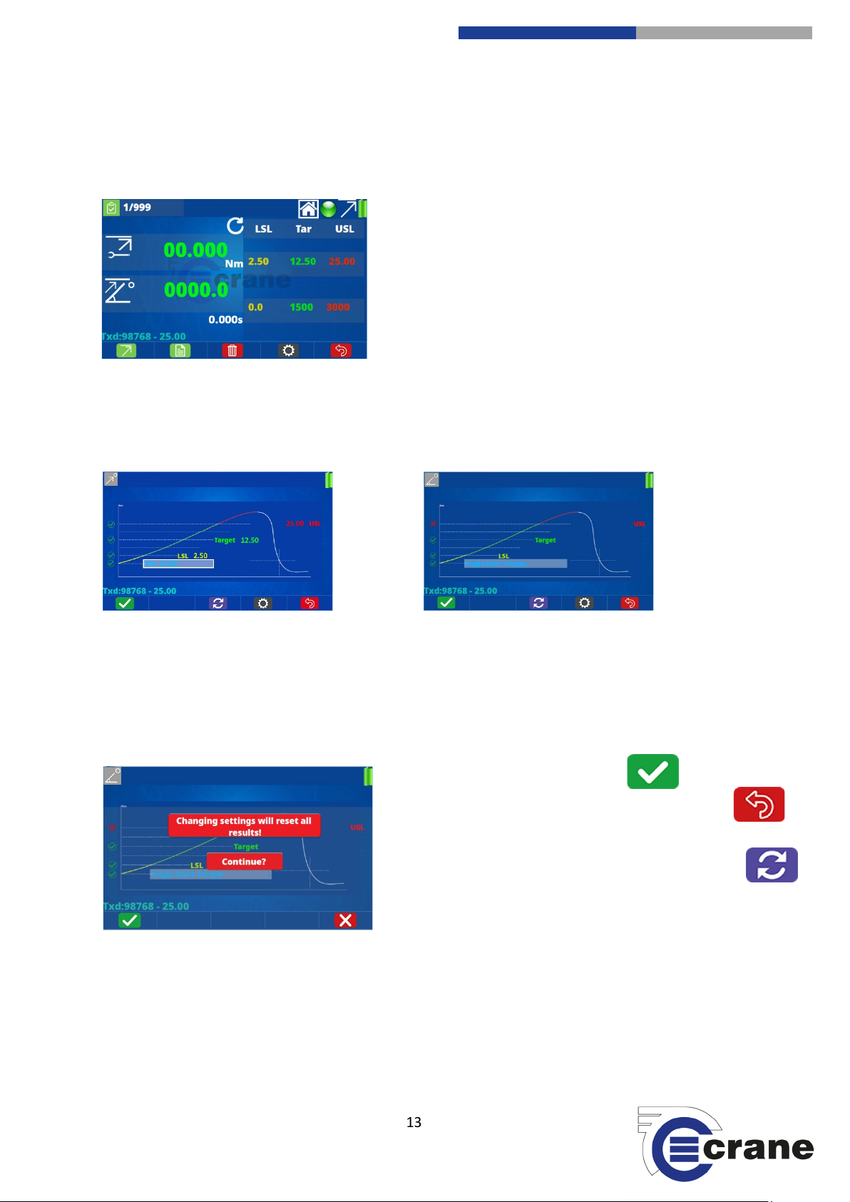
If a transducer is already plugged in then, depending on what span Nm (or torque range), it will automatically
populate the LSL (lower specification limit), target torque and USL (upper specification limit). If the transducer
has angle, this will also automatically be populated.
If you wish to change the LSL, target torque and USL, you can toggle using the Up and Down arrow keys to
highlight the torque and angle limits. The selected function is within a white rectangle. Press the green button
and you will be taken to the screen below. There is a Home icon at the top of the display. If it is highlighted
with the Up and Down arrow keys, pressing the green button will take you back to the Home screen.
Torque Angle
Use the left and right arrows to move to the Limit that you wish to change. When highlighted press the green
button. To change the limits use the Up and Down arrows and the Left and Right arrows to go to another
number. Once you have set the desired number, press the green button. Continue following this process until
all your limit settings are correct.
If you are changing a transducer or changing the limits then this will reset all the results.
If all is OK then press the green ‘tick’.
If this screen isn’t displayed then press the back button
to return to the measuring screen.
If you change your mind before pressing the green tick
icon (F1) then press refresh (F3) to restore original limits.
The settings icon (F4) takes you to measurement settings.
14 88
-electronics.com
13

Crane Electronics Ltd
The force in torque management
Crane Electronics Ltd
Watling Drive
Sketchley Meadows
Hinckley LE10 3EY
Tel: +44(0) 1455 25
www.crane
INPUTS
CHARGING YOUR TORQUESTAR
2 2 1
1
TorqueStar Pro has connectivity using
the following:
1) Micro USB (charging or streaming)
2) USB (USB stick or OMS Lite)
3) 25-way D-type female transducer
port
4) 5V DC Power Supply
Charging can be done in two ways:
1) Connect Micro USB on the TorqueStar to USB on a
laptop/PC or USB charger.
2) Connect the 5V DC port with a DC power supply.
14 88
-electronics.com
14

Crane Electronics Ltd
The force in torque management
Crane Electronics Ltd
Watling Drive
Sketchley Meadows
Hinckley LE10 3EY
Tel: +44(0) 1455 25
www.crane
CONNECTING A TRANSDUCER
MANUAL TRANSDUCER SET UP
Plug the male 25-way D-type connection on the transducer to the
female connection port on the back of the TorqueStar.
All Crane UTA transducers will automatically be recognised.
Industry Standard (IS) Transducers will have to be manually
inputted (See transducer set-up).
You can store up to 10 x IS transducers. You can use 1 x UTA transducer and have 10 x IS stored, or you can
connect 5 x UTA transducers at the same time by using a 5-Way transducer switching box.
5-Way auto transducer switching box:
Allows connection of up to 5 transducers and the capability to switch between
them with ease. Automatic recognition of UTAs and no hardware modifications
are required to connect. Uses 25-way D-type interface.
Part Number: TO-899-09CR-0-0
RS232 Cable Port to Port: CBL-757-0-0-0-0
To manually set up an IS or force transducer select the settings icon from
the Measurement screen and then the transducer icon.
14 88
-electronics.com
You will come to this screen enabling you to set up a transducer. Press the
edit icon to manually input the transducer you wish to connect.
15

Crane Electronics Ltd
The force in torque management
Crane Electronics Ltd
Watling Drive
Sketchley Meadows
Hinckley LE10 3EY
Tel: +44(0) 1455 25
www.crane
Change the transducer properties by using the Left and Right key. Use the
Up and Down arrows to navigate the screen.
Pressing F2 and F4 moves the decimal point.
You can also delete a transducer by pressing the delete icon and
press the green button or the green ‘tick’ to accept and the red
‘cross’ to not delete.
You can always refresh to pair a UTA to the TorqueStar if you have one attached or search for one by pressing
the refresh icon.
Transducer: Set the number of the transducer as you see fit. The TorqueStar can store up to 10 transducers.
Type: Scroll down to type if you are adding an Industry Standard (IS) or Force transducer. All Crane transducers
are automatically recognised and so do not need manual setup. Use arrows to change from IS to Force.
Serial number: To input the serial number, use the keypad to highlight the serial number. Press the green
button on the keypad to highlight the first digit. Use the Up and Down arrows to change this digit and move
left and right to highlight additional digits for editing. Once completed press the green button. Up to 8 digits
can be entered.
Span: To input the span use the same process as for inputting a serial number. Span values 1 – 8000 are
accepted.
Transducer units: Select the measurement unit that you wish to use by using the left and right arrow keys.
Available are: Nm / lbft / lbin / MNm / Ncm / kgcm / kgm / kNm / klbft / Nmm / ozin if IS transducer and N,
kN, kg, kkg, lb, klb if Force transducer.
Pulses per revolution (PPR), Millivolts/Volt, Bridge resistance, Torque @ mV/V: To input these details, follow
the same process as inputting a serial number. Millivolts/Volt can be between 0.500 to 8.000. Bridge
resistance cannot be 0000. PPR = 0 means angle cannot be measured.
14 88
-electronics.com
16

Crane Electronics Ltd
The force in torque management
Crane Electronics Ltd
Watling Drive
Sketchley Meadows
Hinckley LE10 3EY
Tel: +44(0) 1455 25
www.crane
SETTINGS
Settings can be accessed by selecting the Settings Icon on the home screen:
Use Left and Right arrow keys to move between the
different settings functions and select the chosen
function with the green key.
The ‘Back’ icon (F5) will take you back to the previous screen.
Power Settings Date & Time Settings Language Settings Misc. Torque Settings AutoPrint Settings
Readings Settings Comments Settings Unlock TorqueStar Pro Settings Splash screen
14 88
-electronics.com
17

Crane Electronics Ltd
The force in torque management
Crane Electronics Ltd
Watling Drive
Sketchley Meadows
Hinckley LE10 3EY
Tel: +44(0) 1455 25
www.crane
POWER SETTINGS
DATE & TIME SETTINGS
Select the Settings Icon. Select the Power Icon.
You can change the ‘Power Off’ time by using the Up and
Down arrows to highlight the current minutes. Use the Left
and Right arrows to toggle between time limits. You can set
‘Never Off’ or between 1 - 200 minutes.
The same process is followed to change the ‘Backlight Off’
setting. The ‘Buzzer’ can be toggled on or off and the
‘Brightness’ can be changed from 20% - 100%. A lower
brightness saves battery power. ‘Battery’ level is an indicator
to the unit’s power status. If an external power source is
connected, then it will show as 100%.
The ’Backlight Off’ time cannot be greater than the ‘Power Off’ time.
The ‘TM Power Save’ turns the Torque Module power off when not being used to talk to transducers in
measurement mode.
The ‘Timer’ does not operate if an external power supply is connected.
Select the Settings Icon. Select the Date/Time Icon.
Date Format – Using the Up and Down arrows you can navigate.
Highlight the ‘Date Format’ and press of the left or right arrows to
change the format. There are three to choose from:
DD/MM/YYYY, MM/DD/YYYY, YY/MM/DD.
Date – To change the date, highlight the current date stored, press
the green OK button and use the Up and Down arrows to change
the dates. The Left or Right keys switch between day, month and
year. To save, press the green button.
Number Format – Dot or Comma for decimal place.
Time Format – Set how you want the time displayed. HH:MM:SS, HH:MM using the left and right arrow keys.
Time – Highlight the current time, press the green OK button and then you can use the arrow keys to change
the time, using the Left and Right arrows to move between the hours, minutes and seconds.
14 88
-electronics.com
18

Crane Electronics Ltd
The force in torque management
Crane Electronics Ltd
Watling Drive
Sketchley Meadows
Hinckley LE10 3EY
Tel: +44(0) 1455 25
www.crane
LANGUAGE SETTINGS
Select the Settings Icon. Select the Language Settings Icon.
Language Settings.
Use the Left and Right arrow keys to change the language in the TorqueStar. Available languages are: English,
French, German, Chinese, Polish, Hungarian, Italian, Portuguese, Spanish, Turkish, Swedish, Czech.
The TorqueStar stores a log file to aid the solving of any
issues arising in the software.
Save (F1) icon allows the log file to be stored on a USB flash
drive automatically. If no USB drive is available, press the
cancel icon (F1) to return.
The delete icon allows the log file to be deleted. Press accept
or cancel icon.
The logging cannot become full as a FIFO principle is employed to make sure only recent information is
recorded.
Stored in \Crane\logs\ folder on the memory stick as file ‘log.date-time’.
The log file can also be uploaded into OMS and OMS Lite (Pro only).
14 88
-electronics.com
19

Crane Electronics Ltd
The force in torque management
Crane Electronics Ltd
Watling Drive
Sketchley Meadows
Hinckley LE10 3EY
Tel: +44(0) 1455 25
www.crane
MISCELLANEOUS TORQUE SETTINGS
AUTOPRINT SETTINGS
Select the Settings Icon. Select the Misc. Torque Icon.
Use the Up and Down arrows to navigate and use the left
and right arrows to set the user requirement.
Stream to USB updates torque value to the USB continuously
whilst taking readings. Stream is on Micro USB port.
The span of the connected transducer can be added to
stream.
FIFO is First In First Out. If off, it can only take 999 readings.
If on, you can see the last 999 readings.
- Auto Print sets print out for the end of results and in
reading list.
- Trace length: 0 (No trace), 30s (data point every 1ms), 60s
(data point every 2ms) 2 mins, 5 mins, 10 mins, 20 mins, 1
hour, 2 hours, 4 hours, 10 hours.
Select the Settings Icon. Select the AutoPrint Icon.
AutoPrint set-up.
Use the left and right arrows to change the settings, use the
up and down arrows to scroll through the menus.
14 88
-electronics.com
20

Crane Electronics Ltd
The force in torque management
Crane Electronics Ltd
Watling Drive
Sketchley Meadows
Hinckley LE10 3EY
Tel: +44(0) 1455 25
www.crane
UNLOCK
PRO SETTINGS (TorqueStar Pro Only)
Select the Settings Icon. Select the Unlock Icon.
The unlock code can be provided by Crane to enable
features on the TorqueStar. With no unlock code the
TorqueStar will show ‘Demo’ on the splash screen and will
work in basic Plus mode. The Plus unlock code removes
‘Demo’ from the splash screen.
Plus with ‘Graphs’ unlock code allows traces of readings to
be viewed and advanced statistics. These come as standard
on Pro.
Pro unlock code upgrades Plus to Pro. The same hardware and firmware is used so the unit does not need to
be returned to Crane. The unlock code is remembered when the TorqueStar is turned off/on.
Select digit position with Left and Right arrow keys. Select the Hex number (0 – 9 A – F) with Up and Down
arrow keys. Click accept (F1) icon when code is entered. Note: the unlock code is dependent on the serial
number of the TorqueStar so it cannot be shared between devices.
Select the Settings Icon. Select the Pro Settings Icon.
Angle Value can be set as:
- Peak (Angle at Peak Torque)
- Final (Angle seen before torque goes below Angle Start Torque for the final time)
14 88
-electronics.com
21

Crane Electronics Ltd
The force in torque management
Crane Electronics Ltd
Watling Drive
Sketchley Meadows
Hinckley LE10 3EY
Tel: +44(0) 1455 25
www.crane
SETTINGS MEASUREMENT SCREEN
Max. No. of Subgroups
- Set by OMS Lite and is maximum number of subgroups per job. It affects the maximum
number of jobs it can store (Note. the number of jobs stored is also affected by number of readings
per subgroup and can only save a maximum of 20,000 readings).
Select the Settings Icon, when on a measurement screen.
Using the Up and Down arrows on the device you can
select the setting that you require. Using the Left and
Right arrows will change the setting to what you require.
Once completed you can press the return key to go back
to the measurement screen.
Units = Displayed torque units
Direction = Clockwise, Anti-clockwise, Auto
Cycle end time = 0.2s, 0.5s, 1.0s, 2.0s, 5.0s,
10.0s, 20.0s
Freq. response = (Hz) 75, 151, 256, 307, 384,
542, 768, 921, 1024, 1316, 1536, 2304, 3072,
4608
The Menu Slot is the number from the left of the
screen that the measurement icon occupies
Audit Angle is shown when measure mode is
Audit.
14 88
-electronics.com
22

Crane Electronics Ltd
The force in torque management
Crane Electronics Ltd
Watling Drive
Sketchley Meadows
Hinckley LE10 3EY
Tel: +44(0) 1455 25
www.crane
CHECK MEASURING SCREEN
Measuring Screen:
The symbols across the top of the screen are:
Top-left corner icon that appears is relevant to the screen you are currently on.
The TorqueStar has 999 readings capability. Number of readings are displayed.
(Changes from /999 to +000 when it has more than 999 FIFO readings)
Selecting this icon will take you back to the Home Screen.
If this Icon is Green it means that everything is ready to measure.
If this icon is Red then something needs to be actioned and it cannot take a measurement.
Current ‘Measurement Mode’ is displayed
Battery level indicator. A flash will appear when charging.
14 88
-electronics.com
23

Crane Electronics Ltd
The force in torque management
Crane Electronics Ltd
Watling Drive
Sketchley Meadows
Hinckley LE10 3EY
Tel: +44(0) 1455 25
www.crane
Measurement screen
Measurement mode
Direction of rotation
Last reading taken
Last angle measurement
Duration
Angle
Transducer serial no.
LSL = Lower Specification Limits
Tar = Target Torque
USL = Upper Specification Limits
If a reading is below the target torque a number of things will
happen:
1. Torque reading will be yellow when the fixing is under-
tightened.
2. An audible, single beep will be emitted.
3. The yellow LED light on the TorqueStar will illuminate.
If the target torque is achieved there will be two audible beeps and the TorqueStar’s green LED will illuminate.
If the USL is reached then the fixing is too tight the torque reading will be in red and three audible beeps will
be heard and the red LED will illuminate.
The top reading is the torque measurement value and the lower readings will be angle (or secondary
parameter) if applicable.
- No limits shown for Track mode.
- Secondary parameter limits are not shown if not selected in measure settings.
- In Click measurement mode, the Click Dip threshold is set in torque limit settings.
- Duration is corrected at the end to remove cycle end time.
- No direction icon shown for Track mode (CW is positive torque, CCW is negative torque).
- In Audit measure mode an audit angle will be shown below secondary parameter.
- In Track mode, it shows torque, angle and rpm.
14 88
-electronics.com
24

Crane Electronics Ltd
The force in torque management
Crane Electronics Ltd
Watling Drive
Sketchley Meadows
Hinckley LE10 3EY
Tel: +44(0) 1455 25
www.crane
MEASUREMENT OPTIONS
The symbols across the bottom of the screen are your action keys. Pressing the corresponding soft-key will
give you access to other modes and settings.
Choose Measurement Mode
Readings list
Delete
Measurement Settings
Back
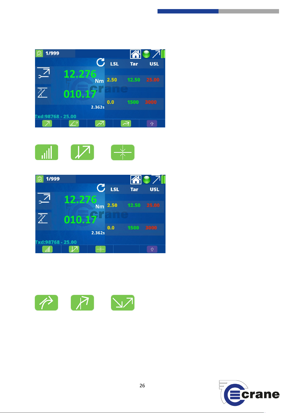
On the front Measuring Screen press the ‘Measurement Mode’ Icon.
You will then see four different Measuring Modes.
Pressing the ‘shift’ arrow icon will take you to additional measurement modes.
Peak Peak Angle Click Track
14 88
-electronics.com
25
Crane Electronics Ltd
The force in torque management
Crane Electronics Ltd
Watling Drive
Sketchley Meadows
Hinckley LE10 3EY
Tel: +44(0) 1455 25
www.crane
Pulse Audit Force
Pro Only:
There are 3 additional measurement modes available with the TorqueStar Pro:
Yield MoveOn Retighten
When you select the measurement mode you require, you are taken back to the measurement screen and, as
long as a transducer is connected, you can begin to measure.
14 88
-electronics.com
26

Crane Electronics Ltd
The force in torque management
Crane Electronics Ltd
Watling Drive
Sketchley Meadows
Hinckley LE10 3EY
Tel: +44(0) 1455 25
www.crane
READING LIST
Pressing the readings list icon will take you to the readings screen.
The ‘Save’ icon will let you save your reading to a USB stick. Insert the USB stick and save to USB.
For further information go to the ‘Saving – USB’ section in this manual.
Saving readings to a USB device:
Insert a USB device into the back of the TorqueStar. The standard USB socket can be located at the rear of the
unit and is sealed with a plastic protector. Remove the protector and insert the USB device.
USB port protector. Insert USB.
When clicking on the Save Icon, you will be asked to insert a USB Stick. The USB Icon will
appear on the screen.
14 88
-electronics.com
The USB Memory Stick icon will automatically go green and save the readings to the USB Stick
if attached.
27

Crane Electronics Ltd
The force in torque management
Crane Electronics Ltd
Watling Drive
Sketchley Meadows
Hinckley LE10 3EY
Tel: +44(0) 1455 25
www.crane
Saves in folder \Crane\Export
READING TRACE
Filename [MeasureMode] Date_Time.csv
Date & time format altered in settings represents the time of export.
We recommend you use the USB flash drive supplied with the TorqueStar (16GB USB 2.0). It is formatted as
FAT32.
The ‘Print’ icon will allow you to print all your readings using format in Auto Print settings.
Pressing the ‘Add Comment’ icon will open a window of text comments. These are different
comments the user is able to add to a reading to give details of any issues that occurred during
the tightening process. Once the required text is highlighted press the ‘ok’ key to confirm and
add this to the reading.
Comments Available:
Operator Error / Slipped / Fastener Missing / Fastener Location /
Prod. Down time / Not on Station / Production Error / Patch Bolt
Set / Loose Fastener / Wrong Fastener / Wrong Tool / Tool
Malfunction / Low Volume / Track Stop / Crossed Thread /
Stripped / Bad Part / Part Shortage / Not Determined
View Statistics of the Readings (see next page).
The ‘Back’ icon will take you back at any time to the measurement screen.
When in the reading list, pressing the green button for a
selected reading will show a graph of the readings.
The icon switches between Torque vs Time,
Angle vs Time and Torque vs Angle.
A red cross (cursor) will highlight the feature found on that measure mode. You can zoom in (except on Torque
vs. Angle)
The up and down arrow keys change the speed of cursor movement. The parameter values at the cursor
position are displayed on the right hand side of the graph. The plus and minus icons allow you to zoom in and
out of the trace. Zoom in centres on the cursor and you can zoom in until all trace points are displayed.
14 88
-electronics.com
28

Crane Electronics Ltd
The force in torque management
Crane Electronics Ltd
Watling Drive
Sketchley Meadows
Hinckley LE10 3EY
Tel: +44(0) 1455 25
www.crane
The save icon saves the results.
STATISTICS
DELETION
Save to folder \Crane\Traces\ [MeasureMode] Date_Time.csv
If taking more than 999 readings (FIFO on) you will only see traces for the last 998 readings.
Statistics
This will show various different statistics taken from the readings taken by the user. They are as follows:
- Qty - Mean
- Min - Max
- Sigma - Range
- Cp - Cm
- Cpk - Cmk
The ‘Back’ icon will take you back at any time to the measurement screen.
You can save these statistics to USB by connecting the USB memory stick into the back of the
TorqueStar and pressing the button corresponding to the ‘save’ icon (F1). This will then open
up another window where the user can save these values. Name Statistics Date.Time.csv in
\Crane\Export. The statistics are for displayed parameter.
The device also gives the unit the option to print out the statistics, this is done by connecting
a printer and then pressing the keyboard button which corresponds with the ‘printer’ icon
(F2).
Swap between displaying Primary and Secondary parameters.
Measuring Screen:
If you have taken a reading and you wish to delete it, you can press the ‘Delete’ icon on the screen.
This will then send you to the delete screen where you can either accept the deletion or reject it.
You can also use the Up and Down arrows to select ‘Delete All’ and this will delete all of the readings currently
taken.
14 88
-electronics.com
29

Crane Electronics Ltd
The force in torque management
Crane Electronics Ltd
Watling Drive
Sketchley Meadows
Hinckley LE10 3EY
Tel: +44(0) 1455 25
www.crane
WARNING SCREENS
Below are a series of warning screens that can appear during operation of the TorqueStar:
14 88
-electronics.com
If you decide to change settings whilst in the middle of readings then you
will be warned. If this is what you wish to do then press the green button, if
not press the button.
Warning messages similar to this will appear if you try and attach or select
the wrong transducer for the job required.
The TorqueStar will warn you if your memory is full. You will need to
upload to a USB, print out your results or delete readings.
If you are trying to select a transducer that is not compatible or choose the
wrong one then you will be issued with a warning message. You can go
back using the red ‘back’ key.
If you have selected the wrong units then you will see this message.
If you attach a new transducer whilst in the middle of readings then this
will erase all the results. Press the green ‘tick’ or the red ‘cross’.
30

Crane Electronics Ltd
The force in torque management
Crane Electronics Ltd
Watling Drive
Sketchley Meadows
Hinckley LE10 3EY
Tel: +44(0) 1455 25
www.crane
Whilst in measuring mode with a selected transducer if you decide to
change the measurement mode then all reading results will be reset.
If you start pulling torque before you are in the measuring screen then you
will be warned that the ‘Zero Offset’ is over-ridden by a certain %.
First phase in retighten measure mode. Untighten in CCW direction.
Second phase in retighten measure mode. Retighten in CW direction until
specified audit angle is reached.
Unfasten torque has to be greater than 10% of attached transducer span.
Invalid unlock code. Check code HEX and re-enter. Make sure it is the
correct code for the device serial number.
If there is a problem with the internal SD card then traces will be disabled.
Over-torqued transducer.
Invalid mode, e.g. trying to use a force transducer for a torque
measurement.
14 88
-electronics.com
31

Crane Electronics Ltd
The force in torque management
Crane Electronics Ltd
Watling Drive
Sketchley Meadows
Hinckley LE10 3EY
Tel: +44(0) 1455 25
www.crane
TORQUESTAR PRO FEATURES
VIRTUAL KEYBOARD
LOGIN SCREEN
When text input is required a virtual keyboard will appear on the screen.
Use the arrow keys to highlight the required character
and press the green button to select it.
If you make a mistake, use the ‘Backspace/Erase’ icon (F1) to delete the previous character.
Use the ‘Shift’ icon (F2) to change between upper and lower case characters.
Use the ’Symbol’ icon (F4) to allow numbers and special characters to be selected.
To exit the keyboard, use the ‘Cancel’ icon (F5) or ‘Enter’ (F3) if you wish to accept the entry.
If a barcode scanner (Model Tera 5100) is connected to a Type A USB, then you can scan the input and
automatically accept.
On the TorqueStar Pro, after leaving the splash screen after powering on, you will enter the login screen.
The users can be downloaded from OMS (Lite).
14 88
-electronics.com
The users can be highlighted with the Left and Right
arrow keys then selected by pressing the green button.
When a user is selected, the virtual keyboard appears
so the password can be entered.
32

Crane Electronics Ltd
The force in torque management
Crane Electronics Ltd
Watling Drive
Sketchley Meadows
Hinckley LE10 3EY
Tel: +44(0) 1455 25
www.crane
COMMUNICATION WITH OMS LITE
HOME SCREEN (PRO ONLY)
There is a default user called ‘admin’ with password ‘Admin’ (Upper case ‘A’).
If the password is correctly entered then you are taken to the Home screen and the username appears in the
top left of the display so you know who is logged in.
If you press the back icon (F5) in the Home screen then you will return to the Login screen and another user
can then log in.
When the TorqueStar Pro is in the Home screen it can communicate with OMS Lite (and OMS).
Connect the Pro to a PC running OMS Lite using a type A-A USB cable.
Jobs, Rounds and Users can be downloaded to the Pro and readings uploaded.
All of the icons on the Home screen are active:
Check (F1) – has functionality described earlier in manual
Jobs (F2) – described later in manual
Rounds (F3) – described later in manual
Settings (F4) – has functionality described earlier in manual
14 88
-electronics.com
33

Crane Electronics Ltd
The force in torque management
Crane Electronics Ltd
Watling Drive
Sketchley Meadows
Hinckley LE10 3EY
Tel: +44(0) 1455 25
www.crane
Back (F5) – returns to the Login screen
JOBS
See a list of jobs downloaded from OMS Lite or created on the TorqueStar Pro.
(F1) Add Job: (Note. you cannot edit jobs downloaded from OMS Lite, just view them)
Once on the ‘Add Job’ screen, you can move between job settings screens with (F4) and (F3)
icons.
You can save the changes to job settings with save (F1) and return without saving with back
(F5).
Screen 1:
Job Name = (appears in Job list)
Job Description = (appears below Job name in Job list)
14 88
-electronics.com
34

Crane Electronics Ltd
The force in torque management
Crane Electronics Ltd
Watling Drive
Sketchley Meadows
Hinckley LE10 3EY
Tel: +44(0) 1455 25
www.crane
Screen 2: General Job Settings
Screen 3: Additional Settings
Number of subgroups = (1 – number in global settings)
Number of readings = (1 – 50)
Job Type = (Peak, Impulse, Yield, MoveOn, Angle Control,
Audit, Force, Retighten, Click Dip)
Retries = (Never, Always, Manual, Single)
Cycle End Time = (0.2s, 0.5s, 1.0s, 2.0s, 5.0s, 10.0s, 20.0s)
Units = (Change if force or torque job type)
Direction = (CW, CCW, Auto)
Frequency Response
Screen 4: Transducer Settings
Job Comment
Subgroup Comment
Subgroup Reference
(For each of the above it can state if it
occurs before or after)
Secondary Parameter = (Could be angle, pulse count or
peak torque depending on job type)
Store Graph = (Never, Always, Manual, NOK)
Audit Angle = (1 – 0 degrees) (Appears if Audit Job Type
selected)
Transducer Mode = (Any appropriate, Fixed Type,
Specific Device)
14 88
-electronics.com
Transducer Type = (UTA, IS, CheckStar Multi, Wrench)
Span = (1 – 8000)
Pulses per rev (PPR)
Transducer Units
Adapter Length
35

Crane Electronics Ltd
The force in torque management
Crane Electronics Ltd
Watling Drive
Sketchley Meadows
Hinckley LE10 3EY
Tel: +44(0) 1455 25
www.crane
Adapter ID
Serial Number = (Up to 8 digits)
If transducer mode is ‘any appropriate’ then any transducer can be used with the job and at the point of use, it
will check the transducer span against job limits (e.g. Span ≥ USL and 10% Span ≤ LSL).
If transducer mode is ‘fixed’ type, then the transducer used must match:
- Transducer Type (UTA, IS, CheckStar Multi, Wrench)
- Span
- PPR
- Transducer Units
- Adapter Length (if wrench)
- Adapter ID (if wrench)
If transducer mode is ‘specific device’, the same as above for ‘fixed type’ applies, plus the serial number of the
transducer to be used.
Screen 5: Primary Parameter Limits & Screen 6: Secondary Parameter limits (if enabled)
Similar to the same screen within ‘Check’ mode.
When adjusting limits (as ‘any appropriate’) you can adjust the decimal point with (F2) (move decimal
point to left) or (F4) (move decimal point to the right).
(F2) Search Job List: Job list allows you to enter a search string which will only display job names
containing that string.
(F3) Delete: Allows you to delete a selected Job.
(F5) Back: Return to the main screen.
14 88
-electronics.com
(F4) Job Setup: Same screens as ‘Add Job’ but to you can view or edit job (if created locally and
no readings are taken).
36

Crane Electronics Ltd
The force in torque management
Crane Electronics Ltd
Watling Drive
Sketchley Meadows
Hinckley LE10 3EY
Tel: +44(0) 1455 25
www.crane
JOB MEASUREMENT SCREEN
When listing jobs, you can see up to 4 at a time. Use the up and down arrow keys to scroll through the job list.
Pressing the green key on a highlighted job enters the job measurement mode.
The job list shows - in the top middle of the display - which job number it is in the list and how many there are
in total.
Against each job it also displays the job type (e.g. peak) and the percentage of completion.
Similar to Check measurement screen plus:
S:X/Y = Informs which subgroup ‘X’ out of ‘Y’ you are in.
Job Name = (e.g. JOB1) is top centre of the display.
Unlocked = (Can take readings)
Locked = (Completed all readings)
Select the Switch View icon to switch between:
- Line Graph = (Readings with LSL & USL limits)
- Torque Thresholds = (View Torque Limits)
14 88
-electronics.com
37

Crane Electronics Ltd
The force in torque management
Crane Electronics Ltd
Watling Drive
Sketchley Meadows
Hinckley LE10 3EY
Tel: +44(0) 1455 25
www.crane
JOB READING LIST SCREEN
JOB STATISTICS
Similar to ‘Check’ reading list screen plus:
Can swap between subgroups using the Left and Right
arrow keys.
Colour of reading is: LO = Amber
OK = Green
HI = Red
Comment can be added for each subgroup and Job.
Similar to ‘Check Statistics’ screen plus:
Can see the following using the Left and Right arrow
keys:
- Individual subgroup basic statistics
- Overall Job basic and advanced statistics
14 88
-electronics.com
38

Crane Electronics Ltd
The force in torque management
Crane Electronics Ltd
Watling Drive
Sketchley Meadows
Hinckley LE10 3EY
Tel: +44(0) 1455 25
www.crane
ROUNDS
You can view the Rounds downloaded or created on the TorqueStar Pro.
You can move through the list (up to 4 rounds displayed) using the up and down arrow keys. Each item in the
list will show a round name and description, the round type, and the percentage of completion.
The round position in the list and the total number of rounds is displayed in the top middle of the display.
(F1) Add Rounds (Note. you cannot edit or delete rounds downloaded from OMS Lite)
You can move between rounds settings screens with (F4) and (F3) icons.
Screen 1:
Round Name = (appear on Round list screen)
Round Description
Directions:
Any order = Select any Job from the Round Job List using
Up and Down arrow keys.
Vertical = Start at the first Job in the Round Job List then
after completing a subgroup in the previous Job, start the
subgroup in the next job on the list.
Note. You cannot add the same Job to more than one Round on the TorqueStar Pro. (It is possible that Rounds
downloaded from OMS Lite might contain the same Job).
14 88
-electronics.com
Horizontal = Start at the first Job in vertical Job List then
perform 1 reading from each Job in the list, before
repeating the process.
Prompt = Prompt after finishing last job before starting
next
39

Crane Electronics Ltd
The force in torque management
Crane Electronics Ltd
Watling Drive
Sketchley Meadows
Hinckley LE10 3EY
Tel: +44(0) 1455 25
www.crane
Screen 2: Select Jobs
Select Jobs from the list using Up and Down arrow keys
and press Enter.
The selected Job will turn green (If you make a mistake,
select the job again and it will turn white).
Screen 3: Select Order
(F2) Search for Round
(F3) Delete Round)
Select Job from the list using the Up and Down arrow
keys.
Pressing the Left and Right arrow keys will shift the
selected Job up and down the list.
(F4) Round Setup
(F5) Back to main screen
14 88
-electronics.com
40

Crane Electronics Ltd
The force in torque management
Crane Electronics Ltd
Watling Drive
Sketchley Meadows
Hinckley LE10 3EY
Tel: +44(0) 1455 25
www.crane
If you press the green key on a selected round, it enters this round. If this is an ‘any order’ round, then you can
choose a job from the job list using the arrow keys or search (F1). Otherwise for vertical and horizontal round
types, the Pro starts at the beginning of the list.
Pressing Back (F5) takes you back to the round list.
14 88
-electronics.com
41
 Loading...