


TorqueStar Opta
& DTT Opta
Operator’s Manual
Manual 890: Issue 7
Crane Electronics Ltd
NOTICE
ALL RIGHTS RESERVED. Reproduction of any part of this manual in any form whatsoever,
without the prior permission in writing from Crane Electronics Ltd is forbidden.
Copyright © March 2012 by Crane Electronics Ltd
The contents of this manual are subject to change without prior notice.

OPERATOR’S MANUAL
2
CE MARKING
Manufacturer: Crane Electronics Ltd.
Address: Watling Drive
Sketchley Meadows
Hinckley
Leicestershire
LE10 3EY
United Kingdom
Tel: +44 (0)1455 251488
Declares that this product has been assessed and complies with the requirements of the relevant CE Directives.
HOW TO USE THIS MANUAL
This manual covers both the TorqueStar Opta and the DTT Opta. As they share similar software and many features are
common to both devices, the manual is split into 2 sections. The 1st (main) section covers the operating instructions for the
TorqueStar Opta and the 2nd section covers only areas where the operation of the two devices differs. This includes the
integral printer of the DTT Opta and its interchangeable transducer modules.
Any DTT Opta procedures not mentioned specifically in the 2nd section, can therefore be taken from the TorqueStar Opta
instructions.

OPERATOR’S MANUAL
3
CONTENTS
CE Marking 2
How to use this manual 2
Contents 3
SECTION 1 - TorqueStar Opta
Packing List 4
Care & Storage 4
Batteries 4
Overview -TorqueStar Opta 5
Features and Dimensions 6
Specifications 7
Controls and Connections 8
Opta Controls 9
Battery Charging 10
Printing 10
RS 232 Terminal Emulator 10
Switching ON 11
Switching OFF 11
Changing the Power Save Options 11
Cold Reset 11
Main Menu 12
To Change the Language 12
To Access Other Modes 12
Tools Menu 12
Logging IN 13
Logging OUT 13
Users 13
Setting the Time and Date 14
Selecting the Quick Read Mode 14
Connecting a Transducer 15
Taking a Reading (Quick Read) 15
Changing the Settings (Quick Read) 16
Plot Trace (Last Reading only) 16
Quick Store Mode 17
Taking a Reading (Quick Store) 18
Changing the Settings (Quick Store) 19
View Readings (Quick Store) 20
View Statistics 21
Plot Readings 21
Jobs 21
View Readings (Jobs) 22
Adding New Jobs to List 23
Rounds 24
Adding New Rounds to List 25
Transducer Templates 25
Using a Bar Code Reader 27
Communications 29
Unlock Feature 29
Glossary of Terms 32
SECTION 2 - DTT Opta
Overview - DTT Opta 33
Packing List 33
Care and Storage 33
Batteries 33
Features and dimensions 34
Specifications 34
Controls and connections 35
Battery charging 36
Printing 36
Connecting a transducer module 37
Fitting a joint kit 37
Fitting the bottle top fixture 37
Using the bottle top fixture 38
DTT mounting template 39

OPERATOR’S MANUAL
4
PACKING LIST
The following items are supplied with the TorqueStar unit.
1 x TorqueStar Opta Digital Torque Reader 1 x User Manual (this book) 1 x Camera (Neck) Strap
1 x Quick start guide 1 x Mains adaptor/charger 1 x Menu Navigation Guide
Please check these items are all present and notify Crane immediately of any shortages.
CARE & STORAGE
This unit is designed for indoor use only
Operating temperature range 5-40 degrees C
Storage temperature range 0-50 degrees C
The membrane keypad may be wiped clean with a soft damp cloth. The unit is not waterproofed and spillages should
be avoided.
THIS UNIT CONTAINS NO USER SERVICEABLE PARTS. ONLY QUALIFIED SERVICE PERSONNEL SHOULD
REPLACE OR FIT PARTS.
BATTERIES
Standard TorqueStar Opta
The battery in the Standard Charge unit is a NiMH (Nickel Metal Hydride).
From fully discharged, the unit will require a 16 hour charge for normal use.
When the mains adaptor is plugged into the socket and switched on at the mains, the red LED will come on to
indicate the Opta is charging correctly.
Optional Fast Charge Opta
TorqueStar Optas with optional Fast Charge, are supplied with internal NiMH (Nickel Metal Hydride) batteries. From
fully discharged, the unit will require a charging period of only 2.5 hours approx. Opta models having this feature are
identified by a tick in the features list - see Unlock feature, page 28.
If the Opta is a fastcharge unit, the green LED will come on to indicate the Opta is charging and will start to flash
when the unit is fully charged. If the red LED comes on, this means there is a problem and usually indicates a faulty
battery.
NOTE: The mains adapter for the Fast Charge model terminates in a slightly larger diameter plug. This prevents the
use of a standard mains adapter for charging the fast charge batteries. No attempt should be made to recharge the
batteries using the standard mains adapter - failure to heed this warning could result in damage to the unit.
SECTION 1

OPERATOR’S MANUAL
5
OVERVIEW - TORQUESTAR OPTA
TorqueStar Opta is the equipment of choice for the measurement and collection of torque data in the manufacturing
environment.
TorqueStar Opta’s range of software features can be individually specified to give a configuration most suited to the
requirement, from a simple no-frills read-out to a comprehensive audit tool with display of torque curves and specialist measurement routines.
The basic TorqueStar Opta performs bi-directional measurement of torque, angle and pulse count in track, peak,
click and pulse measurement modes. For additional information, cycle time duration and tool speed can also be
displayed.
Time and date stamped readings can be set to print automatically. The easy to read display gives a simultaneous
view of all relevant information during the measurement process, while the simple alphanumeric keypad enables fast
data entry when required.
Light enough for carrying on a neckstrap, yet robust to withstand the rigours of the factory environment, TorqueStar
Opta also sports integrated rubber bumpers to protect finished product from accidental damage.
The TorqueStar Opta supports the following features:
• Multiple languages
• Track, peak, 1
st
peak (click) and pulse measurement modes
• Torque, angle, pulse count, cycle time and RPM measurement
• Choice of measurement units
• Plug and play with Crane UTA transducers and wrenches
• Compatible with most 3
rd
party transducers and wrenches
• Selectable auto-print of time and date stamped readings
• Optional Storage of time and date stamped readings
• Optional Basic statistics including range, mean, sigma, Cp and CpK
• Optional Storage of Jobs and rounds including readings
• Optional Operator login with Password Protection
• Optional Bar Code Reader Input
• Optional Graphic Display and Printout of Last Rundown Trace
• Optional PC Communications Package
• Force
SECTION 1
OPERATOR’S MANUAL
6
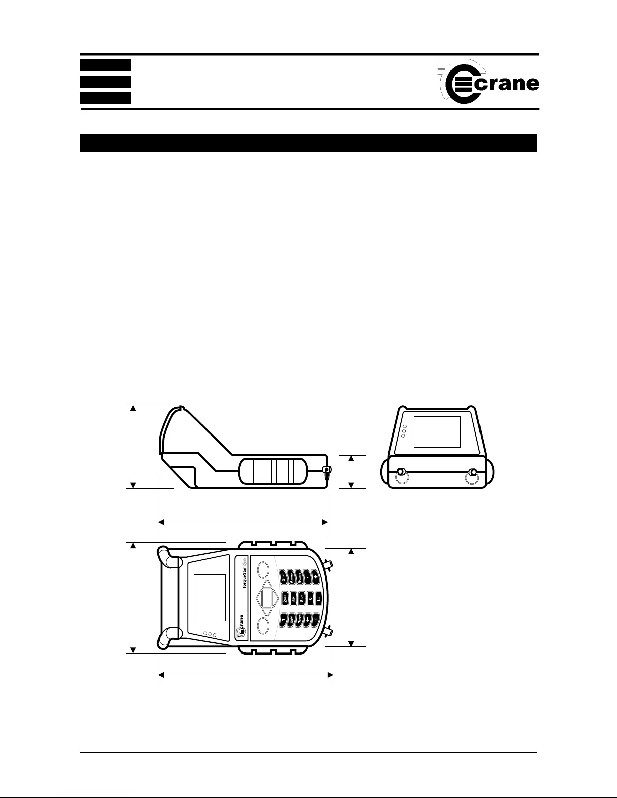
FEATURES AND DIMENSIONS
POWER Rechargeable batteries NiMH
Mains powered (needs optional charger)
WEIGHT Standard Charge - 1.480Kg
Fast Charge - 1.355Kg
CONSTRUCTION Ruggedised injection moulding with rubberised bumpers.
OUTPUT Serial RS 232 Data
DIMENSIONS 255mm (L) x 166mm (W) x 152mm (H)
SECTION 1
250mm
255mmO/A(approx)
166mmO/A
145mm
50mm
152mmO/A

OPERATOR’S MANUAL
7
SPECIFICATIONS
Accuracy: ±1% of rated maximum transducer capacity.
Overload Capacity: 110% of stated maximum transducer capacity.
Zero Drift: <0.1% of rated maximum transducer capacity.
Operating Temperature Range: +5 to +40 degrees Celsius
Temperature Stability: ±0.1% per degree Celsius.
Sealing: IP40.
Humidity: 5% to 75% non condensing.
Serial Interface: 9 way female ‘D’ connector.
Frequency Response: User selectable in 14 steps from 75Hz to 6144Hz
Calibration: Issued with calibration certificate traceable to national
and international standards. 12 months typical
recalibration interval.
Warranty: 12 months parts and labour.
Servicing: Crane Electronics Ltd offer a full repair facility and
calibration to UKAS and international standards.
MAINS ADAPTOR POWER REQUIREMENTS
Standard Charge
Input: 230V AC 50 Hz 300mA (UK and Euro models)
Input: 115V AC 60 Hz 300mA (US models)
Output: 15V DC 800mA (all models)
Fast Charge
Input: 230V AC 50 Hz 700mA (UK and Euro models)
Input: 115V AC 60 Hz 700mA (US models)
Output: 12V DC >1A (all models)
SECTION 1
OPERATOR’S MANUAL
8
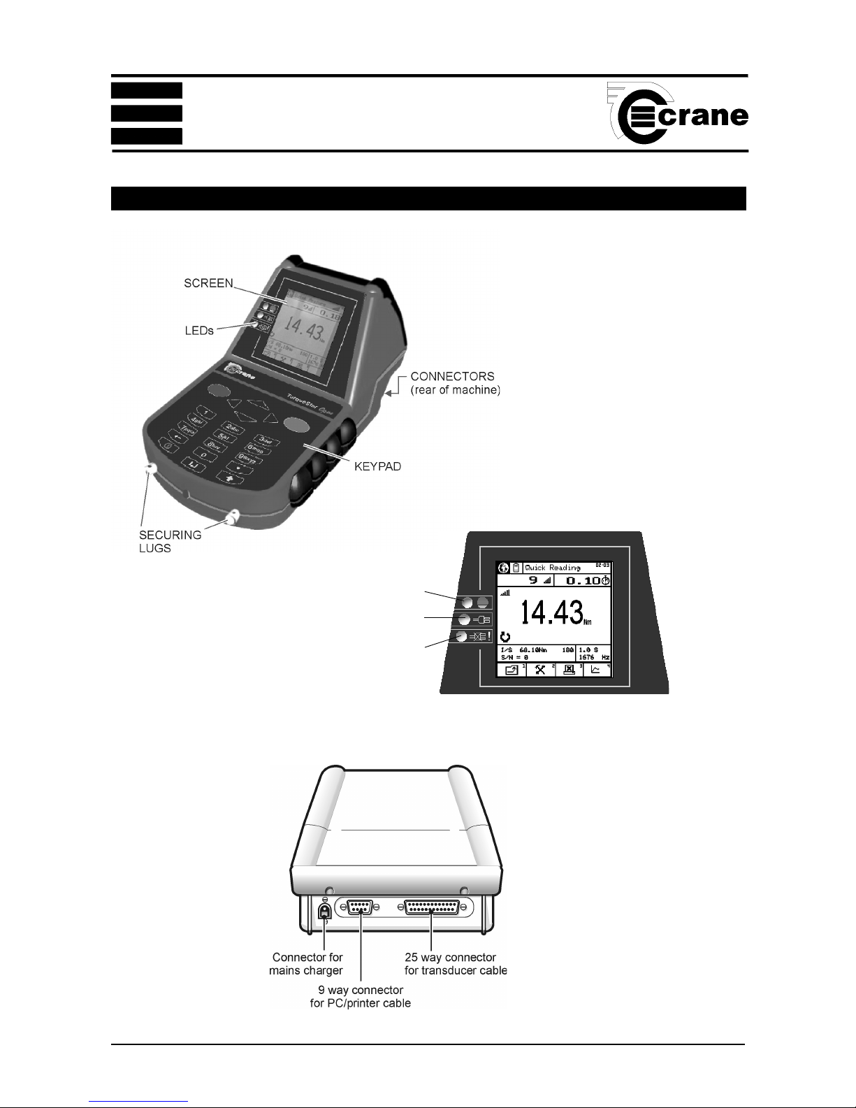
CONTROLS AND CONNECTIONS
STATUS LED
CHARGER CONNECTED LED
CHARGING FAULT LED
(FAST CHARGER ONLY)
REAR OF UNIT
SCREEN
SECTION 1
OPERATOR’S MANUAL
9
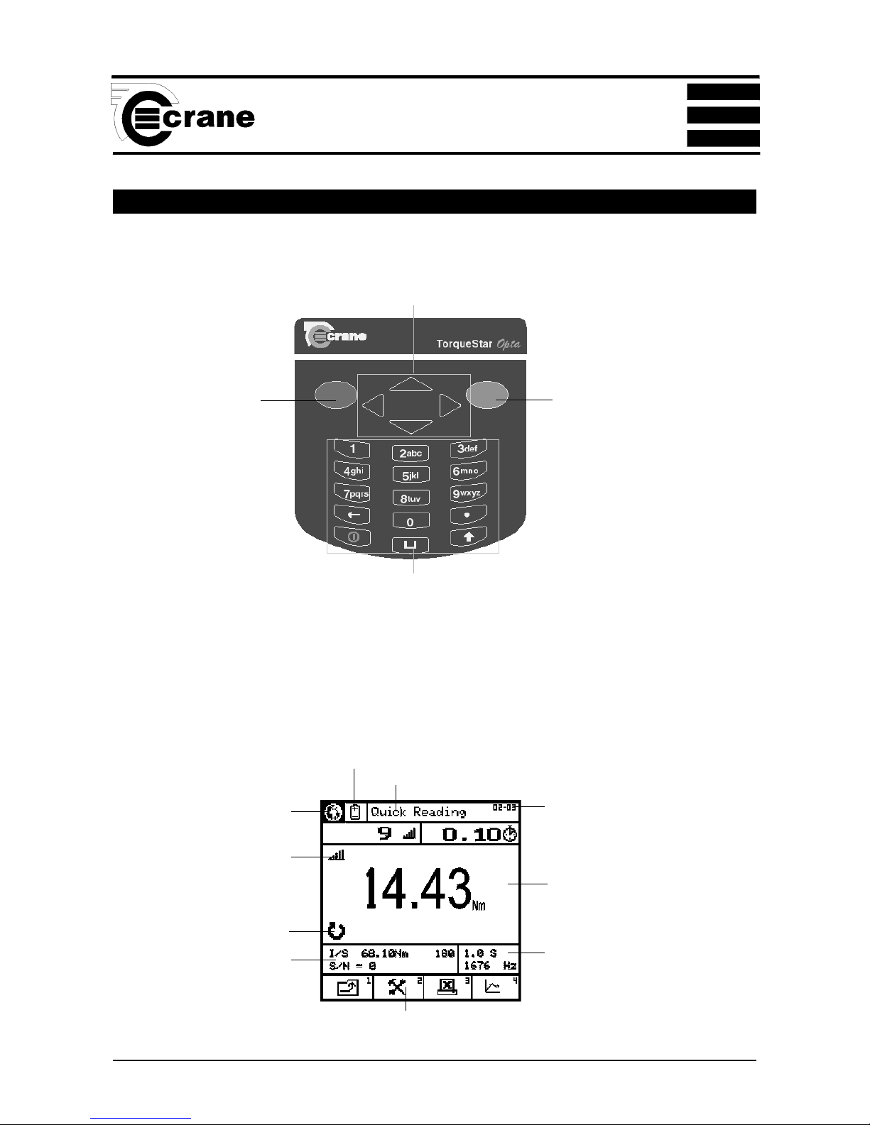
OPTA CONTROLS
Keypad
RED KEY (CANCEL)
- used for cancelling
an option .
GREEN (ENTER)
KEY - used for
confirming a
selection or
accepting an option
etc. Similar to the
Return key on a
computer.
ARROW (CURSOR) KEYS
- used to navigate around the
Opta screen and to move
between fields for editing etc.
ALPHA/NUMERIC KEYS
- used to input numbers or text or to select the numbered functions from the task bar at the bottom of the
screen. For text input, the keys work as a mobile phone keypad. Press the key a number of times until the
correct character is displayed. I.E. to type the letter C, press key 2 3 times.
Screen
TASK BAR
Items here are numbered. Press the equivalent number on the keypad to select.
Main display area for torque readings.
Information varies according to the
mode selected.
Menu icons also displayed here.
Mode selected displayed here
Direction of rotation displayed
here
Transducer information
displayed here
Select here to change language
Select here to change Power
options
Current screen or menu
Menu and subscreen
number
Cycle End Time and Frequency
response displayed here
SECTION 1

OPERATOR’S MANUAL
10
SECTION 1
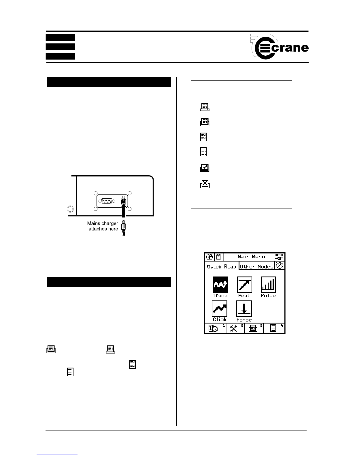
BATTERY CHARGING
The batteries in the TorqueStar unit are shipped fully
charged. In normal use with a transducer connected the
batteries have a life of at least 8 hours.
Connect the lead from the Mains adaptor/Charger to the
mains connector at the back of the TorqueStar Opta (see
below), and connect the mains adaptor to an AC mains
supply. The adaptor can be used for direct power from the
mains or to charge the internal battery. It has an automatic
cut-off to prevent overcharging.
With the unit switched off from a 10% charge state, the
batteries will fully discharge in 25-50 days. To prevent the
loss of all setup data, the unit has additional battery backup
for the internal memory.
ATTACHING A PC OR PRINTER
A PC may be connected to the Torquestar Opta using the
optional PC connection cable CBL-757-0-0-0-0. Attach one
end of the cable to the Torquestar Opta 9 way connector
as shown. The other end of the cable connects to the RS
232 COM Port on the PC or the 9 way end of a USB to
Serial convertor if one is being used. Do not connect a
USB to Serial convertor directly to the Torquestar Opta 9
way connector.
A Serial Printer may be connected to the Torquestar
Opta using the optional PC connection cable CBL-7570-0-0-0 and Serial Printer Adapter CBL-758-01CR-0-0.
Attach one end of the cable to the Torquestar Opta 9
way connector as shown. The 25 way end of the Serial
Printer Adapter connects to the 25 way Serial connector
on the Printer. The printer should be configured to the
following settings:-
Baud Rate = 9600
8 Data Bits
Stop Bit 1
No Parity
Flow Control = None
These are usually factory set as the default settings for
the printer. Note: If the printer has an X on/X off feature
this will need to be set to ON (usually set via DIP
switches on the printer). For further information please
refer to the manual which came with your printer.
To toggle between Autoprint ON or OFF, select the
Autoprint Icon.
Autoprint ON
Autoprint OFF
RS 232 TERMINAL EMULATOR
The TorqueStar Opta can be set to automatically send its
readout data to a suitable RS 232 Terminal Emulator. To do
this, first connect the Opta to the PC Com Port of a Windows
Based PC using the PC to TorqueStar Cable, first ensuring
that the PC is set-up as per the printer settings opposite.
The RS 232 Terminal Emulator will allow date and time
stamped torque readings to be displayed or allow the capture
of data to a text file for export to other software applications.
To toggle between sending readings to RS232 Terminal
Emulator, or not, select the autoprint Icon as above.

OPERATOR’S MANUAL
11
SECTION 1
SWITCHING ON
Press the < ON button on the keypad. The Main Menu
screen now appears.
SWITCHING OFF
From the Main Menu screen select the Power Menu Icon.
From within the Power Menu. Select the power off Icon
to Switch Off the Opta.
CHANGING THE POWER SAVE OPTIONS
From the Power Menu, select tools to enter Power save setup screen.
The user can change the following options:
Charger connected
Auto power off
Backlight off
Charger not connected
Auto power off
Backlight off
Select required Options.
Return to the Power Menu.
Return to the Main Menu.
COLD RESET
CAUTION: THIS FEATURE WILL RESTORE THE OPTA
TO ITS INITIAL FACTORY SETTING. USE THIS FEATURE
WITH CARE, AS ALL SETTINGS AND DATA WILL BE
LOST.
To perform a Cold Reset
From the Main Menu, access the Tools screen.
Select the Reset icon.
The following message will appear on the screen;
ATTENTION!!!
ALL DATA, SETTINGS AND UNLOCKED
FEATURES WILL BE LOST!
Return to the previous menu without change or continue
with the cold reset
The Opta will prompt; “Are you sure?”
Press 2 or
ENTER
Icons used In Cold Reset
Return to previous screen.
Reset
Icons Used in Power Menu
Return to previous screen.
Tools
Switch Off
OPERATOR’S MANUAL
12
SECTION 1
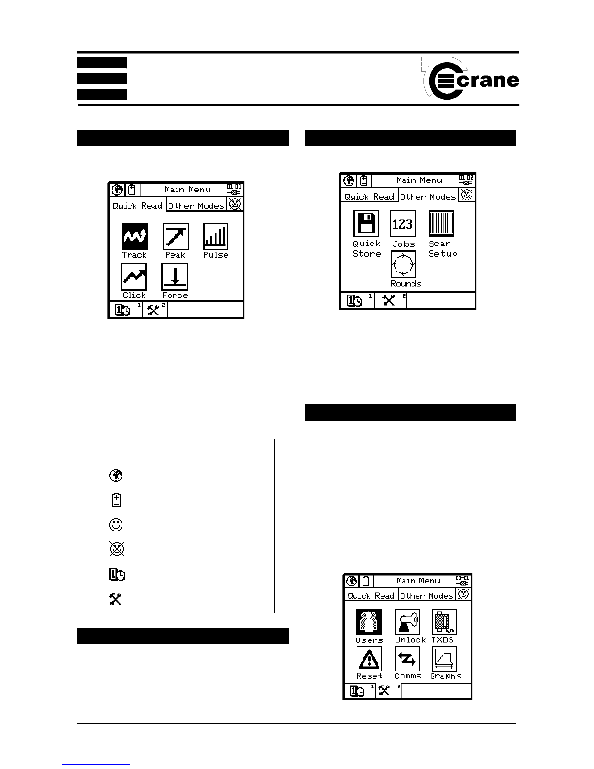
MAIN MENU
This is the default screen for the Opta.
From the Main Menu, the user can change the Language of
the Opta - see below.
To switch off or change the power settings, see page 11.
To set the time and date, see page 14.
To log in or out as a user, see page 13.
To change the Tools settings, see page 12.
TO CHANGE THE LANGUAGE
Select the Change Language Icon.
Select the appropriate language from the list .
The Opta will now be operating in the chosen language.
TO ACCESS OTHER MODES
Select the Other Modes Panel.
Select the required Icon.
The Options are:
Quick Store (see page 17)
Jobs (see page 21)
Scan Setup (see page 27)
Rounds (see page 24)
TOOLS MENU
The Tools Menu gives the user access to the following
features:
USERS - See page 13
UNLOCK - See page 28
TXDS (transducer templates) - See page 25
RESET (Cold reset) - See page 11
COMMS (Communication with a PC) - See page 27
GRAPHS - See page 28
Access the tools menu.
The following screen will appear:
Select required Option.
Icons used in Main Menu
Change Language
Access Power Menu
User logged in
No Users logged in
Time and Date
Tools

OPERATOR’S MANUAL
13
SECTION 1
USERS
The TorqueStar Opta can store up to 10 User names each
with a password. Users from this list can log in to the Opta
(see page 13).
Adding a new user
From the Main Menu screen, select the Tools screen.
Highlight the Users icon
.
From the Users screen, select Add User.
Key in the name using the keypad (press each key the
required number of times until the correct letter is displayed
then pause briefly before moving to the next letter) When
the name is correct, press ENTER.
Repeat this process for the required password.
Repeat to add more users as necessary.
When users are present, they can be viewed using the
Previous User and Next User functions.
Users can be edited by keying in the amended details as for
new users.
Users can be deleted by selecting the Erase User Icon. The
screen will then prompt ‘delete user?’
Press ENTER to Confirm
NOTE:
Only when there are no users, or the first user on the list is
logged in, can changes be made to the user list.
A user must be logged in to record data against Jobs or use
the Scan Setup mode.
LOGGING IN
Select the icon.
The screen will prompt ‘Press Enter to log in’ .
The screen will display a list of users. Highlight and select
the required user.
At the prompt, key in the user’s password and ENTER.
Note: Text is case sensitive.
The screen will now display the user’s name and the log in
time and date.
Either move to another screen or select the Logout icon to
log out.
LOGGING OUT
From the Main Menu, select the icon. Then select the
Logout Icon.
Icons used in the Users Menu
Previous user
Next user
Add user
Edit user
Erase user

OPERATOR’S MANUAL
14
SECTION 1
SELECTING THE QUICK READ MODE
From the Main Menu select Quick Read. The available
modes are:- Track, Peak, Pulse, Click or Force.
NOTE: Before entering the Quick Read Mode, make sure
a suitable transducer is connected to the TorqueStar Opta,
otherwise an error message will be displayed on the screen.
Attach the cable from the transducer to the 25-way D
connector on the back of the TorqueStar.
The selected Quick Read Mode screen will now appear. If
the transducer connected is not a UTA, the transducer
settings must be specified before readings can be taken. In
this case, the screen for the transducer settings, will be
displayed automatically (see Changing the Settings
page 16).
If a UTA transducer is connected, the Opta will automatically
recognise the settings.
SETTING THE TIME AND DATE
From the Main Menu, enter the Time and Date setup screen
- see below. The screen displays the currently set date, week
number, time and the date and time format.
To change Screen Contrast:
Select Contrast. Adjust contrast using left and right arrow
keys.
To change the date:
Select the date. The Date is displayed in editable fields.
Enter the required figures using the numbers on the key-
pad. When date is correct, ENTER to return to the setup
screen.
To change the time:
Select the time. The time is displayed in editable fields.
Enter the required figures using the numbers on the keypad.
When the time is correct, ENTER to return to the setup
screen.
To change the date format:
Select the date format. Highlight the required option and
ENTER to return to the setup menu.
To change the time format:
Select the time format. Highlight the required option and
ENTER to return to the setup menu.

OPERATOR’S MANUAL
15
SECTION 1
CONNECTING A TRANSDUCER
Connect a suitable transducer to the TorqueStar Opta via
the 25-way D connector at the rear of the TorqueStar as
shown. (For DTT - see section 2).
TAKING A READING (QUICK READ)
With the transducer connected to the TorqueStar Opta, apply
torque to the transducer using a suitable tool and observe
the reading on the screen.
This example shows a Pulse Mode screen. The display will
show the amount of torque applied in the chosen Units of
Measure (Nm shown here), the type of transducer and the
serial number. The information on the screen will vary
according to the type of Measure mode selected. The top of
the screen shows the mode selected, as an icon. The
direction of the applied torque is shown if applicable, and
the number of 'pulses' if in Pulse mode, or angle and rpm
if track selected.
Icons used in Quick Read mode
Change Language
Access Power Menu
Return to previous screen.
Setup - change the setup parameters
Autoprint ON/OFF
Plot

OPERATOR’S MANUAL
16
SECTION 1
PLOT TRACE (LAST READING ONLY)
When zoom is selected, a dotted rectangle (marquee)
appears in the display. Use the arrow keys to postion the
panel over the portion of the plot to be magnified and Zoom
In or Zoom out.
To change the Direction of rotation, highlight the required
Direction (Right, Left or Auto) and ENTER.
To change the Cycle End Time, highlight the required
figure from the list and ENTER.
To change the Frequency Response, highlight the
required figure from the list and ENTER.
To change the Torque Threshold, key in the required
figure (between the max. and min. displayed on screen)
and ENTER.
To change the 2nd Parameter, choose between Angle and
None and ENTER.
To change the Angle Threshold, key in the required figure
(between the max. and min. displayed on screen) and
ENTER .
CHANGING THE SETTINGS (QUICK READ)
To change the settings for the chosen Quick Read mode,
select the Settings icon
The screen will now display the Settings Menu and the user
can change some or all the following:-
Transducer settings for non UTA only
Units of Measurement
Direction
Cycle End Time
Frequency Response
Torque Threshold
Second Parameter
Second Parameter Threshold (if applicable).
To view addiitional parameters select previous or next
page keys.
The options available will vary according to the chosen
measure mode.
To change the Units of Measurement, highlight the
required Units from the list and ENTER.
Icons used In Quick Setup
Return to previous screen.
Previous page
Next page

OPERATOR’S MANUAL
17
SECTION 1
From the Select Axis menu the user can select:-
Torque v Time
Secondary (parameter) v Time
(if secondary param. is available)
Torque v Secondary (parameter)
Toggle between highest value or average in between points.
QUICK STORE MODE
When the TorqueStar Opta is switched on, the default
mode is Quick Reading. To access other modes select the
Other Modes panel.
A new screen appears. Select the Quick Store icon.
Highlight the Quick Store icon and select.
The available modes are: Peak, Pulse or Click.
NOTE: Before entering the QUICK STORE Mode, make
sure a suitable transducer is connected to the TorqueStar
Icons used in Plot Screen
Fine movement
(of cursor/zoom box)
Toggle
Coarse movement
(of cursor/zoom box)
Print graph
Zoom
Toggle
Cursor
Zoom in
Toggle
Zoom out
Move
Toggle
Resize
Change axis
Highest value
Toggle
Average
Scroll graph left
Scroll graph right

OPERATOR’S MANUAL
18
SECTION 1
TAKING A READING (QUICK STORE)
With the transducer connected to the Torquestar Opta, apply
torque to the transducer using a suitable tool and observe
the reading on the screen.
This example shows a Pulse Mode screen. The display will
show the amount of torque applied in the chosen Units of
Measure (Nm shown here), the type of transducer , the serial
number, Cycle End Time and Frequency Response. The
information on the screen will vary according to the type of
Measure mode selected.The top of the screen shows the
mode selected, as an icon. The direction of the applied
torque is shown if applicable, and the number of 'pulses' if
in Pulse mode.
Opta, otherwise an error message will be displayed on the
screen. Attach the cable from the transducer to the 25- way
D connector on the back of the TorqueStar (see page15).
The selected Quick Store Mode screen will now appear. If
the transducer connected is not a UTA, the transducer
settings must be specified before readings can be taken. In
this case, the screen for the transducer settings, will be
displayed automatically (see Changing the Settings page
19).
If a UTA transducer is connected, the Opta will automatically
recognise the settings.
The top LED will light to show the status of the reading:-
AMBER - Measurement is below the preset minimum torque
setting. An arrow pointing down will appear on the screen to
confirm and the machine will give a single beep.
GREEN - Measurement is OK (within the specified torque
range) and the machine will give 2 beeps.
RED - Measurement is above the preset maximum setting.
An arrow pointing up will appear in the display and the
machine will give 3 beeps.
Access the Fault Case Indicator screen for a particular
reading.
Screen will prompt to ‘Select fault’
Options are No Fault, Stripped Thread, Double Hit, Blind
Hole, Crossed Thread, Other Bolt Cause or Operator
Error. Select an option. This option enables user to mark a
particular reading to be ignored for the purpose of analysis.
Screen will prompt ‘Select Action’ .
Options are; Do Quality Check, Replace Bolt, Report,
Investigate or Other Actions.
Changing the Autosave option.
In the default mode, with the symbol showing, all readings
are saved automatically. Changing the symbol will cause
readings to not to be saved unless the ENTER button is
pressed. The prompt will now read ‘Store Reading’. Pressing
ENTER will store, pressing CANCEL will ignore the reading
and allow the user to continue. A tick or cross appears on
the screen to confirm the action taken.
View the list of the torque readings stored and their status.
The display will show the torque and secondary parameter
(if any) for the stored readings and their status. See
page 20.

OPERATOR’S MANUAL
19
SECTION 1
CHANGING THE SETTINGS (QUICK STORE)
To change the settings for the chosen Quick Reading mode,
select the Settings icon
The screen will now display the Settings Menu and the user
can change some or all the following settings:
Non UTA Transducer Settings
Units of Measurement
Direction
Cycle End Time
Frequency Response
Torque Threshold
Torque USL
Target
Torque LSL
Second Parameter
Second Parameter Threshold (if applicable).
Second Parameter USL
Second Parameter Target
Second Parameter LSL
The options available will vary according to the chosen
measure mode.
To change the Units of Measurement, highlight the
required Units from the list and ENTER.
To change the Direction of rotation, highlight the required
Direction (Right, Left or Auto) and ENTER.
To change the Cycle End Time, highlight the required figure
from the list and ENTER.
To change the Frequency Response, highlight the
required figure from the list and ENTER.
Icons used in the Quick Store mode
Fault cause indicator
Auto save ON
Autosave OFF press green ENTER button
to override
View readings
Statistics
Plot readings
Print
Delete
Include marked readings
Exclude marked readings
Toggle Torque/Second
parameter
Scroll Left
Scroll Right

OPERATOR’S MANUAL
20
SECTION 1
To change the Torque Threshold, key in the required figure
(between the max. and min. displayed on screen) and ENTER.
To change the Torque USL (Upper Specification Limit),
key in the required figure (between the max. and min.
displayed on screen) and ENTER.
NOTE: The Torque USL and LSL can be displayed as
either a figure in the chosen Units of Measurement or as a
percentage of the USL. To change, highlight the desired
option (radio button) and ENTER.
To change the Target Torque, key in the required figure
(between the max. and min. displayed on screen) and ENTER.
To change the Torque LSL (Lower Specification Limit),
key in the required figure (between the max. and min.
displayed on screen) and ENTER.
To change the 2nd Parameter, choose between Angle and
None, and Pulse Count (for Pulse measurements only) and
ENTER.
To change the Angle Threshold, key in the required figure
(between the max. and min. displayed on screen) and ENTER.
To change the 2nd Param. USL (Upper Specification
Limit), key in the required figure (between the max. and min.
displayed on screen) and ENTER.
NOTE: The Second Param. USL and LSL can be displayed
as either an angle or as a percentage of the USL. To change,
highlight the desired option (radio button) and ENTER.
To change the 2nd Param.Target, key in the required figure
VIEW READINGS (QUICK STORE)
From the Quick Store mode select View readings.
A list of the current readings will appear in a similar format
to the one shown below.
View Readings
# Torque Angle
Nm
001 10.05 OK 0.0 OK
002 10.04 OK 0.0 OK
003 10.11 OK 0.0 OK
004 20.01 HI 0.0 OK
005 20.05 HI 0.0 OK
006 8.50 OK 0.0 OK
007 10.11 OK 0.0 OK
008 3.11 LO 0.0 OK
009 10.12 OK 0.0 OK
This will show the number of each reading, the torque value
in the chosen Units of Measurement, the angle (if applicable)
and the status of the reading (Hi, LO or OK). Scroll down
the readings to access any not able to fit on to the screen.
Scroll left and right to view their values.
Options Available:
View the statistics for the list. See View Statistics. Page 21
See a plot of the readings. See Plot Readings. Page 21
Print the list.
Erase the list, the screen will prompt ‘Erase all readings?’
To return to the readings without erasing, CANCEL.
(between the max. and min. displayed on screen) and ENTER.
To change the 2nd Param. LSL (Lower Specificaton
Limit), key in the required figure (between the max. and min.
displayed on screen) and ENTER.

OPERATOR’S MANUAL
21
SECTION 1
VIEW STATISTICS
The View Statistics screen shows the following information
for the last group of readings taken:
x - (x-Bar) - for both Torque and Angle (if applicable)
R - for both Torque and Angle (if applicable)
s - (sigma) - for both Torque and Angle (if applicable)
To change the size of the samples from which the statistics
are based, highlight and select the figure Key in the required
number (between 0 and 200) and ENTER.
Note: Entering a figure of 0 will base the statistics over all
readings.
Select Option to include readings marked for a fault and
again to exclude them.
PLOT READINGS
From the Quick Store mode select View readings.
From the View Readings screen, select Plot the Readings.
The Plot Readings screen will appear showing the plot and
the Upper and lower limits.
Scroll the plot to the right to view any points not able to fit on
to the screen or Scroll to the left.
Select Icon to toggle between Torque and Second Parameter
if selected.
JOBS
NOTE: A user must be logged in before any Job can be
performed.
The TorqueStar Opta can store a number of jobs consisting
of 1 - 50 Subgroups, each containing up to 1 - 30 samples.
These are stored with an optional user’s comment for
subsequent sequences of readings.
To access the Jobs mode
From the Main menu - Other Modes screen, select the Jobs
icon.
The Jobs screen will appear.
The list shows up to 5 jobs per screen up to a maximum of
275 jobs.
NOTE: If the Show Description box is checked select and
each page will show a single Job plus the description. Select
the box again to clear and return to normal listing.

OPERATOR’S MANUAL
22
SECTION 1
Access the Reading Status screen for a particular reading.
Screen will prompt to ‘Select fault’
Options are No Fault, Stripped Thread, Double Hit, Blind
Hole, Crossed Thread, Other Bolt Cause or Operator
Error. Select an option . This option enables user to mark
a particular reading to be ignored for the purpose of analysis.
Screen will prompt ‘Select Action’ .
Options are; Do Quality Check, Replace Bolt, Report,
Investigate or Other Actions.
Change the Autostore option.
In the default mode, with the symbol showing, all readings
are saved automatically. Changing the symbol will cause
readings not to be saved unless the ENTER button is
pressed. The prompt will now read ‘Store Reading’. Pressing
the ENTER button will store. Pressing the CANCEL button
will ignore the reading and allow the user to continue.
A tick or cross appears on the screen to confirm the action
taken.
View a list of the torque readings stored and their status.
The display will show the torque and secondary parameter
(if any) for the stored readings and their status.
View the statistics for the list of readings.
In the Statistics display toggle between including or excluding
any readings marked for faults as described.
Show a plot for the readings. See page 21.
VIEW READINGS (JOBS)
From Jobs mode select View Readings.
A list of the current readings will appear in a similar format
to the one shown in Quick Store, with the addition of the
Subgroup number, the date and time, the transducer serial
number and the Job name.
Scroll down the readings to access any not able to fit on to
the screen. Scroll left and right to view their values.
Options Available
View readings (see page 22).
Add a new Job (see page 23).
Edit a Job
Delete a job
Select the required job. The Perform Job screen will now
appear ready to accept a series of readings. This is similar
to the Quick Store screen with the addition of the Job name,
the subgroup number, and an additional option for adding a
comment to jobs and subgroups.
As the readings are taken, the number of readings will be
counted until the target figure is reached. The number of
subgroups within the job will also be counted. The Opta
beeps twice afer each reading and 3 times when the end of
each group has been counted.
The following icons appearing next to Jobs in the list indicate
the following:
Options Available
Add a comment to the job.
Toggle sending data to the printer (see page 10)
View the plot trace (see page 16)
= job in progress.
= job has been completed.

OPERATOR’S MANUAL
23
SECTION 1
Options Available
View the statistics for the list. See View Statistics page 21.
See a plot of the readings. See Plot Readings page 21.
Print the list.
Erase the list. The screen will prompt ‘Erase all readings?’
To return to the readings without erasing CANCEL.
ADDING NEW JOBS TO LIST
Select add a new job.
Key in required Job name and ENTER.
Screen will prompt ‘Key in job description’ , ENTER.
Key in the job description and ENTER.
To edit the transducer settings enter the Transducer Template
screen. Select a transducer from the list (options are Auto
ID or 9 user editable options (to change these, see page
25).
The following parameters can be set in the Jobs Mode:
Job Name
Job description
Number of samples
Number of subgroups
Measure Mode
Job Comment
Comment length
Reference length
Edit transducer details
Span
Units of Measurement
Pulse per Rev
Direction
Cycle End Time
Frequency Response
Torque Threshold
Torque USL
Target
Torque LSL
Second Parameter
Second Parameter Threshold (if applicable).
Second Parameter USL
Second Parameter Target
Second Parameter LSL
The Job setup parameters are stored over several pages.
To access these move to the next page or move to the
previous page.
Altering these parameters is similar to the setup in the Quick
Store Mode.
To edit the number of samples to be taken, select Samples
and key in the required figure (between the minimum and
maximum shown on screen).
To edit the number of subgroups to be taken, select Samples
and key in the required figure (between the minimum and
maximum shown on screen).
To change the Units of Measurement, select the required
Units from the list.
To change the Direction of rotation, select the required
Direction (Right, Left or Auto) .
To change the Cycle End Time, select the required figure
from the list.
To change the Frequency Response, select the required
figure from the list.
To change the Torque Threshold, key in the required figure
(between the max. and min. displayed on screen).
To change the Torque USL (Upper Specification Limit),
key in the required figure (between the max. and min.
displayed on screen).
NOTE: The Torque USL and LSL can be displayed as either
a figure in the chosen Units of Measurement or as a
percentage of the USL. To change, select the desired option
(radio button).
To change the Target Torque, key in the required figure
(between the max. and min. displayed on screen).

OPERATOR’S MANUAL
24
SECTION 1
ROUNDS
NOTE: A user must be logged in before any Round can be
performed.
A round is a series of Jobs to be performed together as a
group. Each round must contain at least 2 Jobs.
To access the Rounds mode
From the Main menu - Other Modes screen, select the
Rounds icon. The Rounds screen will appear.
The list shows up to 5 rounds per screen.
Note: If the Show Description box is checked each page
will show a single Round plus the description. Select the
box again to clear.
Select the required round. The Perform Job screen will now
appear ready to accept a series of readings for the first Job
in the Round. This is the same screen as in the Jobs mode.
As the user takes readings, the Opta will count down each
Job subgroup showing the name of the Job (see Jobs Mode
page 21) until all of the Jobs in the Round are complete.
The Opta screen will now return to the Rounds List.
Select another round to perform or return to the Other Modes
Menu.
To change the Torque LSL (Lower Specification Limit),
key in the required figure (between the max. and min.
displayed on screen).
To change the 2nd Parameter, choose between Angle,
Pulse and None.
To change the Angle Threshold, key in the required figure
(between the max. and min. displayed on screen).
To change the 2nd Param. USL (Upper Specification
Limit), key in the required figure (between the max. and
min. displayed on screen).
NOTE: The Second Param.USL and LSL can be displayed
as either an angle or as a percentage of the USL. To change,
select the desired option (radio button).
To change the 2nd Param.Target, key in the required figure
(between the max. and min. displayed on screen).
To change the 2nd Param. LSL (Lower Specification
Limit), key in the required figure (between the max. and
min. displayed on screen).
Check boxes next to Job Comment, Comment and
Reference can be used to ensure the user is prompted to
enter comments at the appropriate time.
Icons used in the Jobs Menu
Add comment
Job in progress
Job completed
Add job
Edit job
Delete job
Select transducer

OPERATOR’S MANUAL
25
SECTION 1
Options Available
Add a new Round
Edit a Round
Delete a Round
Note: rounds completed or in progress cannot be deleted
or edited.
The following icons will appear next to the the Round number
to indicate the status of the Round.
= Round in progress.
= Round has been completed.
ADDING NEW ROUNDS TO LIST
To add a new round
Key in the name for the round at the prompt and ENTER.
Select the description field.
Use the alpha-numeric keys to enter the round description
and ENTER.
Icons used in the Rounds Menu
Job in progress
Job completed
Return to previous screen.
Previous page
Next page
View Round
Add Round
Edit Round
Delete Round
TRANSDUCER TEMPLATES
The TorqueStar Opta has 9 preset transducer templates
which are editable by the user. This can be selected by the
user in Jobs mode if the transducer is non UTA and therefore
not recognised by the Opta.
Select the Sampling field.
Select the required sampling option from the list .
Options are; In any order, Vertical, Horizontal, Vert.
plus prompt, Horiz. plus prompt.
To add a Job to the Round.
Select add a new Job.
Select the required job from the list.
Continue this process until you have selected all the required
jobs for the round.
To save the round.
Opta will prompt ‘Add round to list?’
ENTER to accept or CANCEL to skip without saving.
Icons used in the Rounds
Setup
Return to previous screen.
Previous page
Next page
Edit Round
Add Job
Edit Job
Move job up list
Move job down list
Delete Job

OPERATOR’S MANUAL
26
SECTION 1
To change the transducer type, select the required
Transducer Type (UTA, I/S or H/O). To return to the Txd
Templates screen without change CANCEL.
To Change the Span, key in the required figure (between
the max. and min. displayed on screen) and ENTER. To
return to the Txd Templates screen without change CANCEL.
To change the Transducer Units of Measure, select the
required option from the list. To return to the Txd Templates
screen without change CANCEL.
To change the Pulses per Rev, key in the required figure
(between the max. and min. displayed on screen) . To return
to the Txd Templates screen without change CANCEL.
To change the Millivolts/Volts, key in the required figure
(between the max. and min. displayed on screen). To return
to the Txd Templates screen without change CANCEL.
To change the Bridge Resistance, key in the required figure
(between the max. and min. displayed on screen). To return
to the Txd Templates screen without change CANCEL.
The figure to the right of the Transducer type indicates the
transducer setup (1-9).
To edit the Transducer Templates.
From the Main Menu access the Tools screen
From the Tools Screen, select the TXDs Icon.
The options available will depend on the type of transducer
selected.
From the TXD Templates screen select the option(s) to be
altered and edit .
Icons used In Transducer Setup
Return to previous screen.
Previous transducer
Next transducer

OPERATOR’S MANUAL
27
SECTION 1
USING A BAR CODE READER
A Bar Code Reader can be used to input barcoded numbers
into the Opta. Crane recommends using a PSC QS 6000
Plus handheld laser scanner with RS232 output and
individual power supply suitable for code 39 or 3 of 9. For
use of other bar code readers, please refer to Crane
Electronics Ltd.
In Quick Store mode, barcode input is available for Industry
Standard transducer serial numbers.
Connecting the Bar Code Reader
Connect the Bar Code Reader to the Printer/PC connector
at the rear of the Opta.
NOTE: for additional information, please refer to the
documentation which came with your scanner.
Before First Use:
The scanner must be setup by scanning the three codes on
page 28.
Certain text fields on the TorqueStar Opta will allow the input
of barcode data.
We recommend the data is only scanned once, and the green
ENTER key is pressed to verify the data is correct.
Jobs Mode
Barcode input is available for Industry Standard (IS) serial
number. Additionally, Barcode input is available in the
following modes:
nn
nn
n Job Name
nn
nn
n Description
nn
nn
n Search Field
nn
nn
n Subgroup Comment
nn
nn
n Subgroup Reference
Rounds Mode
nn
nn
n Create Round Name
nn
nn
n Description
nn
nn
n Search Field

OPERATOR’S MANUAL
28
SECTION 1
BAR CODE READER INITIAL SETUP
These bar codes must be scanned in this order to initialise
the reader before first use.
SET -----------------------------------------------
DISABLE LABEL I.D. CONTROL --------------------
END ------------------------------------------------

OPERATOR’S MANUAL
29
SECTION 1
UNLOCK FEATURE
Each Opta is supplied with a Certificate of Authenticity which
shows a software activation code (4 blocks of 4 digits) and a
list of the features available to the machine.
If the Opta has been reset, the code will have to be re-
activated to unlock the Opta and allow it to use all its features.
To unlock the Opta, from the main menu select the Tools
menu.
Select the Unlock icon.
The activation code will appear on the screen with an
arrow below the first digit.
The display will now show the communications screen.
For Information on using Opta Comms software, see the
Opta Comms Manual.
COMMUNICATIONS
The Opta can be connected to a Windows based PC to
upload and download data using the Opta Comms software
available from Crane.
Connecting to a PC
Using the PC to Torquestar cable, connect the Opta to the
PC COM port .
To activate Comms mode, from the Main Menu select Tools.
Select the Comms icon.

OPERATOR’S MANUAL
30
SECTION 1
Use the
and keys to move the arrow across all of
the digits in turn, and the
and arrow to cycle
through the alpha numeric characters to input the correct
digits until the code displayed is the same as the one on the
certificate.
Options available:
Activate the Unlock Code.
The software is now unlocked. Features marked with a tick
are available to the user.
List Features
Return to Previous Screen
NOTE :
Any items not ticked in the list may be encountered during
operating the Opta as greyed out items. When attempts are
made to access these icons, an alert message will appear
advising the user that this item is currently unavailable. It is
possible for the user to upgrade to include these options by
contacting Crane Electronics Ltd. An update activation code
can be supplied to enable the user to access these features
without the need to return the Opta to the factory.
GRAPHS
TorqueStar Opta allows the selection of the maximum
duration of the Trace function.
Select the time required to suit your application.
Icons used in the Unlock screen
Return to previous screen.
Activate unlock code
List features

OPERATOR’S MANUAL
31
SECTION 1
GLOSSARY OF TERMS
Cp
This is a capability index which shows the process capability
potential but takes no account of how centred the process
is. This is used for capability studies and Cp may range in
value from 0 to infinity. A large value indicates greater
potential capability and a value of 1.33 or greater is desirable.
Max - Min
Cp =
6 s
(Max and Min are limit values)
CpK
This is an index which indicates whether the process will
produce units within the tolerance limits. If the process is
centred on the nominal value then CpK will have a value
equal to Cp. For values of CpK between 0 and 1 then some
of the 6 sigma spread will fall outside tolerance limits but for
values greater then 1 these will all be within tolerance. A
negative value of CpK indicates that the process mean is
outside tolerance limits. A value of 1.33 or greater is
desirable.
(Max - x-) (x- - Min)
CpK = lesser of
3 s
or
3 s
(Max and Min are limit values)
CAM
This is an alternative capability index requiring a minimum
of 30 readings to be taken. In this implementation, 5 sub-
groups of 6 samples are used for each calculation. The CAM
calculation uses the following formula:
Max - Min x Cam Factor *
6 x Average Sample Value
* CAM Factor is taken from a table (in the case of 5 x 6
samples = 1.910)
High Output
Torque transducer with no coding links but internal pre-
amplifierTransducer (H/O) giving an output signal level of
typically 1 or 2 volts.
Horizontal
Collection of data by round, taking one reading for each
sampling Job in turn.
Industry Standard Transducer (I/S)
Type of transducer, with no pre-amplifier or coding links, but
with the exact rated torque, marked on the body.
Job
Specification of one particular torque value to be collected.
Each Job has a name of up to 14 characters, 8 if
downloaded from a PC. TorqueStar Opta can store up to
275 different Jobs at any one time.
Master Round
A sequence of up to five rounds. It is used to allow a collection
sequence, which is part vertical, part horizontal.
Max Torque Value
Upper tolerance level of any reading. This can equal but not
exceed the torque rating of the transducer to be used.
Min Torque Value
Lower tolerance level of any reading.
No. of Sub Groups
Number used to allocate memory space in TorqueStar Opta,
for a particular Job. May be set in the range of 1 to 50.
Round
A sequence of Jobs to be collected either horizontally or
vertically. Each round has a name of up to 14 characters, 8
if downloaded from the PC.
Sample
Individual torque reading.

OPERATOR’S MANUAL
32
SECTION 1
Standard Deviation σ
Is a measure of the variation of the samples of a statistical
group.
If a group of n values has a mean of x then its standard
deviation is given by;
Sub - Group
Grouping of samples to enable analysis, with an allowable
range of 1 - 50.
Threshold Torque Value
Level of torque, which a signal must rise above and then
fall below, to be considered a valid torque cycle. This may
be set in the range of 1 to 50% of rated span or the Min
Torque Value, whichever is the lower.
Units of Measure
It is possible with TorqueStar Opta to read a transducer
calibrated in say Nm, and convert internally to display and
store in any of the other torque units.
UTA Tx
Family of torque transducers which TorqueStar Opta can
identify by coding links.
UTA Tx ID
Specification of transducer by rating in preselected units.
Used as an identity or ‘name’.
Vertical
Collection of data by round, where a full sub-group is
collected for a characteristic, before stepping to the next
Job.
Vertical plus Prompt
Identical in procedure to that of Vertical mode except that
before stepping to the next characteristic, TorqueStar will
prompt for the fitting of a transducer (even though the correct
one is installed) and will require the ENTER key to be
pressed.

OPERATOR’S MANUAL
33
OVERVIEW - DTT OPTA
DTT Opta introduces a world of choice, features and flexibility to the tool test environment, with
interchangable transducer modules, built-in printer option, and software features tailored to the
application requirement.
These options allow DTT Opta to be configured to closely match the user requirements, and a selection
of transducer modules can be made available to the operator to cover a broad torque range. Different
transducer modules are available with the transducer axis in either the vertical or horizontal plane.
In common with the Opta product family, DTT Opta’s range of software features can be individually
specified giving variations from a simple no-frills readout to a comprehensive audit tool with display of
torque curves and specialist measurement routines. As the software is common throughout the Opta
product family, users familiar with TorqueStar Opta will already know how to use DTT Opta, and vice-
versa.
PACKING LIST
The following items are supplied with the DTT Opta unit.
1 x DTT Opta 1 x Transducer 1 x User Manual (this book)
1 x Quick start guide 1 x Mains adaptor/charger 1 x Menu Navigation Guide
Please check these items are all present and notify Crane immediately of any shortages.
CARE & STORAGE
This unit is designed for indoor use only
Operating temperature range 5-40 degrees C
Storage temperature range 0-50 degrees C
The membrane keypad may be wiped clean with a soft damp cloth. The unit is not waterproofed and spillages should
be avoided.
THIS UNIT CONTAINS NO USER SERVICEABLE PARTS. ONLY QUALIFIED SERVICE PERSONNEL SHOULD
REPLACE OR FIT PARTS.
BATTERIES
The battery in the DTT Opta is a NiMH (Nickel Metal Hydride).
From fully discharged, the unit will require a 16 hour charge for normal use.
When the mains adaptor is plugged into the socket and switched on at the mains, the red LED will come on to
indicate the DTT Opta is charging correctly.
SECTION 2

OPERATOR’S MANUAL
34
FEATURES AND DIMENSIONS
POWER Rechargeable batteries NiMH
Mains powered (needs optional charger)
WEIGHT Main Unit 3.5 Kg (without transducer and printer)
Transducer Module 1.3 Kg
Printer Module 0.22 Kg
DIMENSIONS Overall 255mm (L) x 255mm (W) x 79mm (H)
Transducer 105 mm (L) x 85 mm (W) x 79 mm (H)
Bottle top or adjustable component fixture:
10 - 130 mm (max gripping dimensions)
SPECIFICATIONS
MAINS ADAPTOR POWER REQUIREMENTS
Input: 230v AC 50HZ 700mA (UK and Euro models)
Input: 115v AC 60HZ 700mA (US models)
SECTION 2

OPERATOR’S MANUAL
35
CONTROLS AND CONNECTIONS
Screen
SCREEN
KEYPAD
LEDs
INTEGRAL
PRINTER (optional)
INTERCHANGEABLE
TRANSDUCER MODULE
(VERTICAL)
JOINT KIT (OPTIONAL)
STATUS LED
CHARGER CONNECTED LED
CONNECTOR FOR MAINS
CHARGER
9 WAY CONNECTOR FOR
PC/PRINTER CABLE
CONNECTORS FOR
TRANSDUCER
MODULE
REAR OF UNIT
SCREEN
INTERCHANGEABLE
TRANSDUCER MODULE
(HORIZONTAL)
FIXING HOLES
FIXING HOLES
TRANSDUCER BOLT
FIXING HOLES
SECTION 2
OPERATOR’S MANUAL
36
SECTION 2
BATTERY CHARGING
The batteries in the DTT Opta unit are shipped fully charged.
In normal use with a transducer connected the batteries
have a life of at least 8 hours.
Connect the lead from the Mains adaptor/Charger to the
mains connector at the back of the DTT Opta (see below),
and connect the mains adaptor to an AC mains supply. The
adaptor can be used for direct power from the mains or to
charge the internal battery. It has an automatic cut-off to
prevent overcharging.
With the unit switched off from a 10% charge state, the
batteries will fully discharge in 25-50 days. To prevent the
loss of all setup data, the unit has additional battery backup
for the internal memory.
PRINTING
Printing
The DTT Opta can be set to automatically send its
readout data to a serial printer or the unit’s optional
integral printer.
Press 3 to toggle between Integral printer
and external printer .
Press 4 to toggle between the 2 different
print formats - Single line spacing
or double line
spacing
.
For information about using an external printer, see the
TorqueStar Opta section at the front of this manual.
Icons used for printing
External printer
Integral printer
Internal printer format (1)
Internal printer format (2)
Autoprint on
Autoprint off
Main Menu screen for DTT Opta

OPERATOR’S MANUAL
37
SECTION 2
CONNECTING A TRANSDUCER MODULE
FITTING THE JOINT KIT
Ensure joint kit is located fully into Square Drive on the
Transducer Module.
FITTING THE BOTTLE TOP OR
ADJUSTABLE COMPONENT FIXTURE
Ensure bottle top fixture is located fully into Square Drive
on the Transducer Module.
OPERATOR’S MANUAL
38
SECTION 2
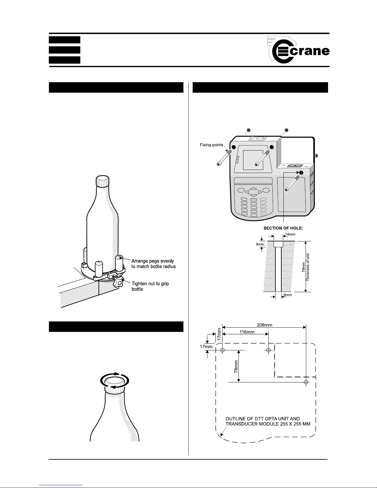
LOADING A BOTTLE
Position the white pegs on the top, so that they grip the
bottle evenly when the black adjustment knob is tightened
to hold the bottle. (Try to get the bottle as near to the
centre of the round turntable as possible). It is possible to
clamp a bottle or container from 10mm to 130mm in
diameter. Ensure that the white pegs are properly seated
in the slots so that they cannot rotate when the bottle
closure is turned.
MEASURING THE TORQUE
Select the desired operating mode from Section 1. Tighten
or release the closure as required to obtain readings.
MOUNTING THE UNIT
The DTT Opta is designed for optional wall mounting as
shown in the details below. The fixings are not supplied.
Fixing hole positions

Remove this page to use as a template for the fixing holes
 Loading...