

Page 1
CFS_DRV_1109
IOM 0A03775B
DOUBLE REGULATING AND
COMMISSIONING VALVES
D921/923 - D931/933/934 - DP931/933/934
Crane Double Regulation Valve (DRV) & Fixed Orifice Double Regulation Valve (FODRV);
• are Y-pattern globe valves having characterised disks tending towards equal
percentage performance
• the double regulating feature allows valve opening to be set with an 3mm Allen key
• operation of the valve is by means of the Microset hand wheel
• the D921/D923 DRV and D931/D933/D934 FODRV valves are WRAS approved
• the DP931/DP933/DP934FODRV are designed as ʻCompanion Valvesʼ for the
Differential Pressure Control Valve
LIMITS OF USE
These installation, operation and maintenance instructions have been categorised in
accordance with the Pressure Equipment Directive – PED.
The fluid to be transported is limited to Group 2 liquids i.e. non-hazardous.
On no account must these valves be used on any Group 1 liquids, Group 1 gases
or Group 2 gases.
I
NSTALLATION AND OPERATING INSTRUCTIONS
COMMISSIONING
In the D931/D933/D934 and DP931/DP933/DP934 ranges, the flow rate is established by
measuring the differential pressure using the P84 test points - red is high pressure and blue
is low pressure. All valves are fitted with our ʻMicrosetʼ handwheel, which indicates the
valve set position, open to shut is 4 complete turns. The outer ring indicates 1/10th of turns
and the inner window indicates complete turns open, ie. a reading of 3 in the inner window
and 1 on the outer ring indicates 3.1 open; 4 being fully open.
Set flow rate as follows;
• connect measuring device to test points following the connection procedure specified by
the manufacturer of the device
• either by calculation or use of graphs, equate differential pressure to flow rate.
Graphs are available on our website or from our technical department
• flow regulation is achieved by adjusting the handwheel position
• once design flow rate is achieved, note handwheel position. The handwheel contains a
setting facility which should be used to maintain the set position, this can be set
as follows;
- remove cap in centre of handwheel
- using a 3mm Allen key tighten the centre screw until it stops, care should be taken
not to over tighten
- replace centre cap
- the valve can now be closed to isolate but will only open to the set position
www.cranefs.com
• Designed and manufactured under quality management
systems in accordance with BS EN ISO 9001-2008
The Company reserve the right to amend any product without notice.
FM311
ISO 9001
www.cranebsu.com
CRANE HOUSE, EPSILON TERRACE
WEST ROAD, IPSWICH
SUFFOLK IP3 9FJ
TELEPHONE: +44 (0)1473 277300
FAX: +44 (0)1473 277301
EMAIL: enquiries@cranefs.com
Page 2
INSTALLATION
02
CRANE FLUID SYSTEMS DOUBLE REGULATING AND COMMISSIONING VALVES
03
CRANE FLUID SYSTEMS DOUBLE REGULATING AND COMMISSIONING VALVES
I
NSTALLATION AND OPERATING INSTRUCTIONS
TEMPERATURE / PRESSURE RATING
DP931/DP933/DP934 - when used with compression fittings
These instructions are issued as guidelines only and do not cover all installed conditions – if
unsure please contact our Technical Helpline before installation.
• Crane products are designed for installation and use within suitably designed systems
reflecting CIBSE, BSRIA and HVAC guidelines. Particular care should be taking
with regards to;
- accessibility to valve for setting/adjustment
- tube cutting
- jointing
- bracketing/supports
• where possible the D921/D923 should be installed in a run of pipework of the same
nominal diameter and with the flow in the correct direction. There is no requirement for
straight lengths of pipework for DRVs
• the D931/D933/D934 and the DP931/DP933/DP934 must be installed in a run of
pipework of the same nominal diameter and with the flow direction as indicated
on the body.
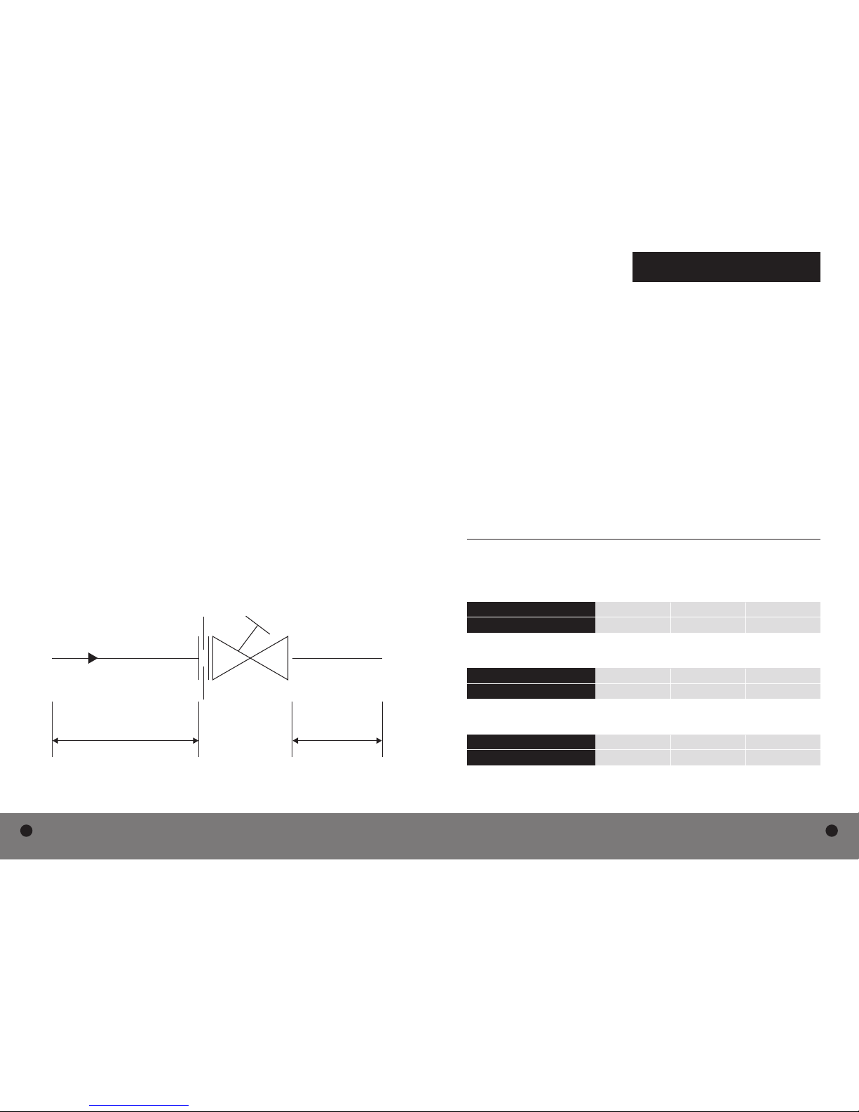
- to ensure flow measurement accuracy, it is essential that the pipework on the inlet
and outlet is straight, is of the same diameter as the valve and has a minimum length
equivalent to 5 diameters on the inlet and 2 diameters on the outlet
- Note: the requirement for 5 and 2 clear diameters are minimum requirements. Where
possible longer lengths should be achieved
- if installed near to pump outlet, it is essential that the straight lengths of pipework
between pump and valve inlet is a minimum of 10 diameters, greater if possible
• the DP931/DP933/DP934 Companion Valves should be installed in the opposite pipework
to the DPCV, ie. DPCV installed in return pipework – Companion Valve installed in flow
pipework. The Companion Valve should be connected to the DPCV via the impulse tube
(supplied with the DPCV). If required an isolation valve can be installed in the
impulse tube
• for the DP931/DP933/DP934 because the impulse tube is connected with a compression
fitting, the temperature and pressure ratings are limited to PN16 rating as follows. If the
valve is used separately, ie impulse tube connection blanked off, the full pressure rating
applies, ie PN25.
• end connections are as follows;
- for sizes ½” to 2”, D921/D923/D931/D933/D934 have female ISO 228-1 parallel threads
suitable for connection to threaded steel pipework. ½” and ¾”, when used with the
compression adaptor, are suitable for connection to BSEN1057- half hard copper.
- the DP931/DP933/DP934 have male threaded ends to ISO228-1 parallel, therefore
require a flat face sealing gasket suitable for the service.
TEMPERATURE ˚C -10 to 30 65 120
PRESSURE (BAR) 16 10 5
D921/D923/D931/D933/D934 - when not used with compression fittings
TEMPERATURE ˚C -10 to 100 110 120
PRESSURE (BAR) 25 23.4 21.8
D921/D922/D931/D933/D934 when used with compression fittings
TEMPERATURE ˚C -10 to 30 65 120
PRESSURE (BAR) 16 10 5
2D5D
 Loading...