

Crane Dominator PRO Z4000 Series Installation, Operating And Maintenance Instructions
INSTALLATION, OPERATING AND MAINTENANCE INSTRUCTIONS
These instructions cover the general
points of notice for the following
Z4000 Series units;
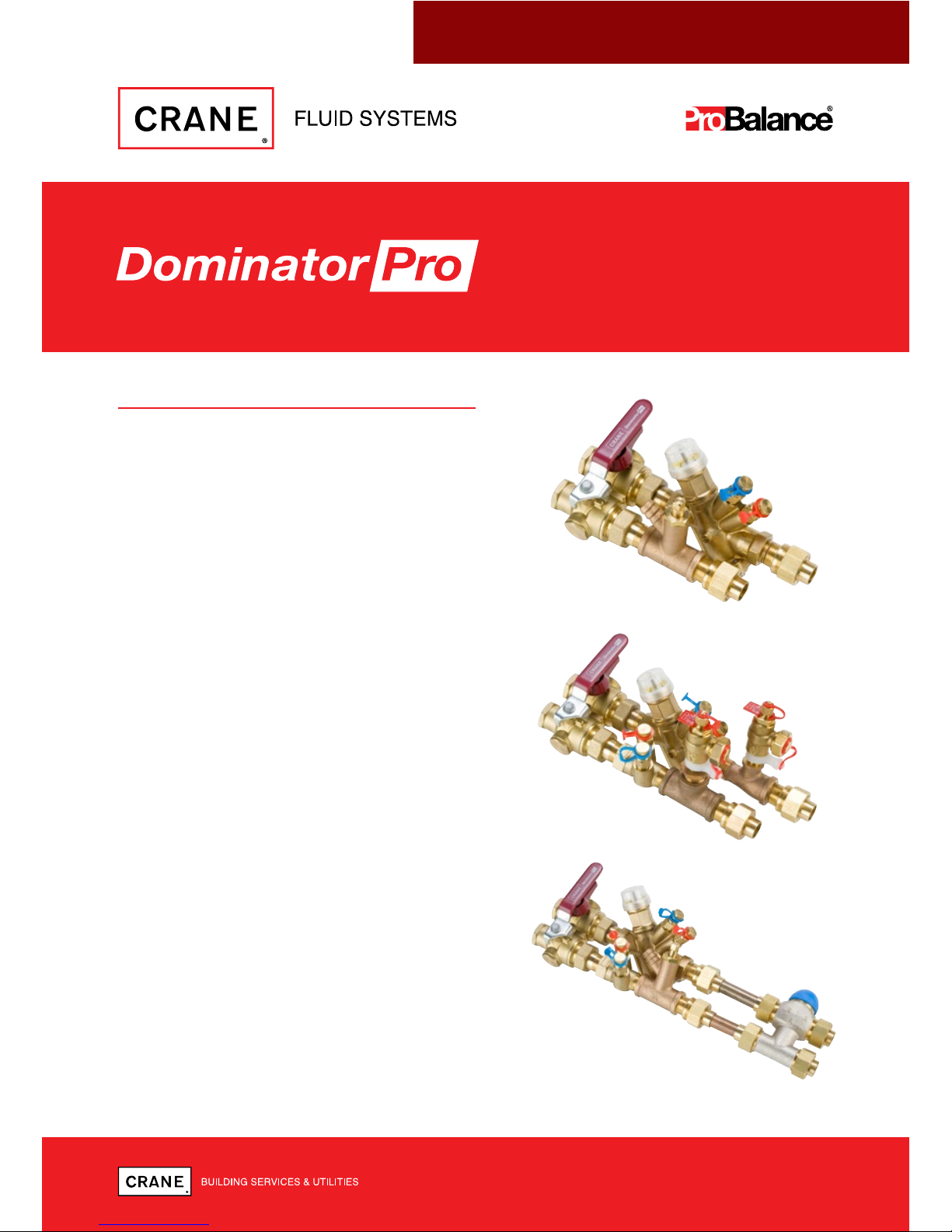
• Flow management system for fan coil
units.
• Solder adaptor for end fitting onto
copper tube as per BS EN 1254-1.
• Taper thread to form a mechanical seal
as per BS EN 10226.
• Combines essential control components
and connecting pipework into one
compact, fully assembled unit ready to
connect.
• The Dominator Pro is compact and ultra
light weight.
• The bypass valve unit comprises two 3
Way Ball valves.
• Includes the Crane PICV (Pressure
Independent Control Valve) for optimum
flow control.
®
Z4000 SERIES
CRANE FLUID SYSTEMS DOMINATOR PRO Z4000 SERIES
02
INSTALLATION
The valve may be installed directly or remotely to a load (typically a Fan Coil Unit).The direction
of flow should be such that the PICV is on the return from the load.
PREPARATION/FITTING
Steel tube - cut square and de-burr internally and externally, thread to BS EN 10226-2 and fit to
Dominator using PTFE tape to BS7786:1995 or other recommended jointing compound. Other
types of piping system can be used providing a suitable adaptor with a threaded end is utilised.
Whilst fitting pipe and/or adapters it is important that the wrench is positioned close to
the joint to be assembled, in order to avoid damaging the valve.
The Dominator Pro shall be supported using proprietary mounting brackets or other suitable
devices see FIGURE 2 this enables the pipework to be well supported and avoids undue strain
on the joints of the Dominator Pro.
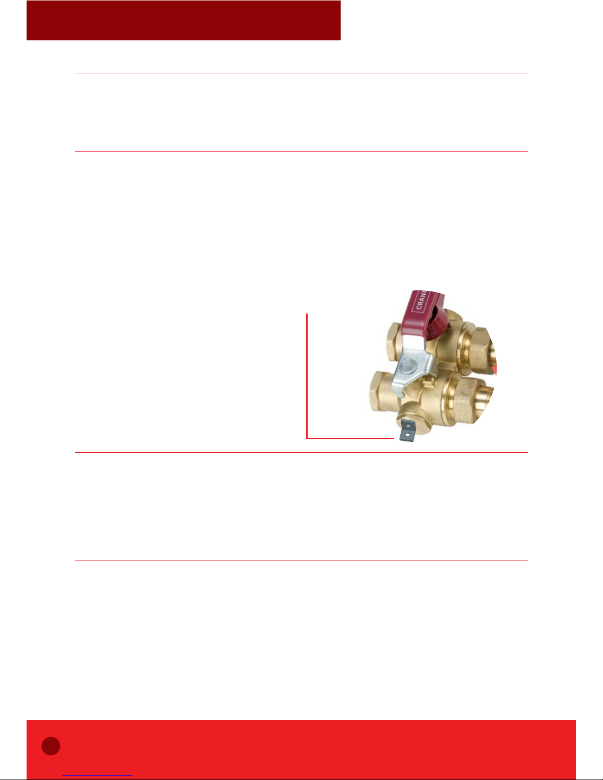
OPERATION
Bypass valve
The bypass valve has four primary modes of operation. It is factory set in Isolation/Flushing i.e.
the bypass mode. The mode of operation can be changed by setting the ‘T’ handles/levers as
indicated in Figure 1.
MAINTENANCE
Bypass valve
This valve is intended for group 2 liquids only, as defined by the Pressure Equipment Directive
2014/68/EU.
For further assistance please call our technical helpline on +44 (0) 1473 277400 or email us at:
enquiries@cranefs.com.
Following a policy of continuous improvement, Crane Fluid Systems reserves the right to alter
specifications shown in this document and the e-catalogue without prior notice.
FIGURE 2:
INSTALLATION, OPERATING AND MAINTENANCE INSTRUCTIONS
 Loading...