

Crane DEMING 4201 Series, DEMING 4221 Series, DEMING 4211 Series Installation, Operation & Maintenance Manual
DEMING
®
DEMING
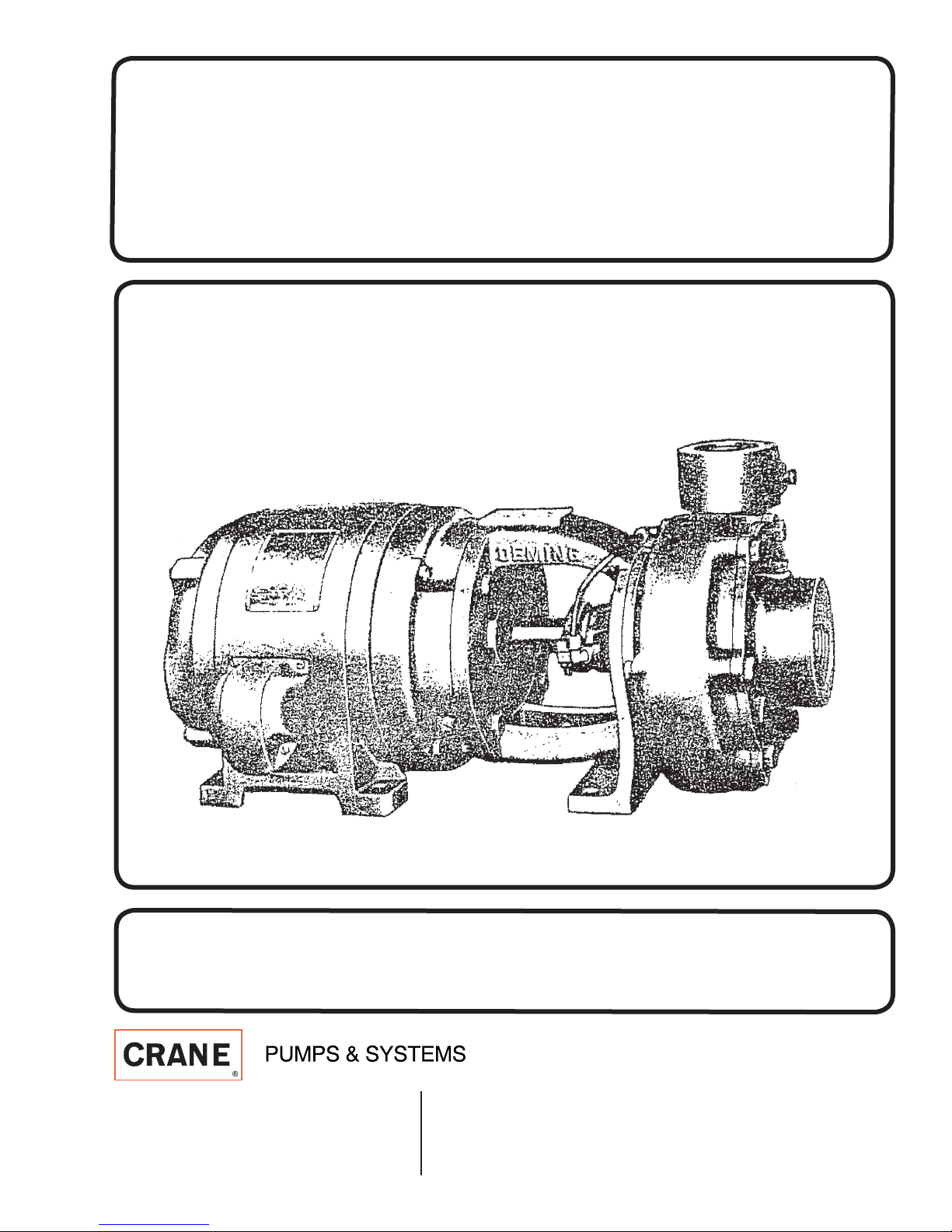
INSTALLATION, OPERATION & MAINTENANCE MANUAL
MotorMount Centrifugal Pumps
Series: 4201, 4211, 4221
IMPORTANT! Read all instructions in this manual before operating pump.
As a result of Crane Pumps & Systems, Inc., constant product improvement program,
product changes may occur. As such Crane Pumps & Systems reserves the right to
change product without prior written notifi cation.
A Crane Co. Company
420 Third Street 83 West Drive, Bramton
Piqua, Ohio 45356 Ontario, Canada L6T 2J6
Phone: (937) 778-8947 Phone: (905) 457-6223
Fax: (937) 773-7157 Fax: (905) 457-2650
www.cranepumps.com
Form No. 120005-Rev. D

CONTENTS
A. GENERAL INFORMATION ...............................................................4
Receiving
Storage
Service Centers
B. INSTALLATION ................................................................................4 - 5
Foundation
Piping
Wiring / Rotation
C. OPERATION .....................................................................................5
Starting
Priming
D. MAINTENANCE ...............................................................................6
Lubrication
Packing
Single Seal
Double Seal
Proper Adjustment of Stuffi ng Box
E. REPAIR ............................................................................................6 - 9
Disassembly of Liquid End
Reassembly of Liquid End
Repacking Standard Stuffi ng Box
Replace Single Mechanical Seal
Replace Double Mechanical Seal
SAFETY FIRST ................................................................................3
F. LOCATING TROUBLE .....................................................................9
CROSS-SECTION & PARTS LIST ...................................................10
WARRANTY & RETURNED GOODS ..............................................11
Other brand and product names are trademarks or registered trademarks of their respective holders.
Deming® is a registered trademark of Crane Pumps & Systems, Inc.
1996, 8/06 Alteration Rights Reserved
2
SAFETY FIRST!
Please Read This Before Installing Or Operating Pump.
This information is provided for SAFETY and to PREVENT
EQUIPMENT PROBLEMS. To help recognize this information,
observe the following symbols:
IMPORTANT! Warns about hazards that can result
in personal injury orIndicates factors concerned with
assembly, installation, operation, or maintenance which
could result in damage to the machine or equipment if
ignored.
CAUTION! Warns about hazards that can or will cause minor
personal injury or property damage if ignored. Used with symbols
below.
WARNING! Warns about hazards that can or will cause serious
personal injury, death, or major property damage if ignored. Used
with symbols below.
Hazardous fl uids can
cause fi re or explo-
sions, burnes or death
could result.
Biohazard can cause
serious personal injury.
Rotating machinery
Amputation or severe
laceration can result.
Only qualifi ed personnel should install, operate and repair
pump. Any wiring of pumps should be performed by a qualifi ed
electrician.
WARNING ! To reduce risk of electrical shock, pumps and
control panels must be properly grounded in accordance
with the National Electric Code (NEC) or the Canadian
Electrical Code (CEC) and all applicable state, province,
local codes and ordinances. Improper grounding voids
warranty.
WARNING! To reduce risk of electrical shock, always
disconnect the pump from the power source before
handling or servicing. Lock out power and tag.
WARNING! Operation against a closed
discharge valve will cause premature bearing
and seal failure on any pump, and on end
suction and self priming pump the heat build
may cause the generation of steam with resulting dangerous
pressures. It is recommended that a high case temperature
switch or pressure relief valve be installed on the pump body.
CAUTION ! Pumps build up heat and pressure
during operation-allow time for pumps to cool
before handling or servicing.
Extremely hot - Severe
burnes can occur on contact.
Hazardous fl uids can Hazard-
ous pressure, eruptions or explosions could cause personal
injury or property damage.
Hazardous voltage can
shock, burn or cause death.
WARNING ! Do not wear loose clothing that may
become entangled in moving parts.
WARNING ! Keep clear of suction and discharge
openings. DO NOT insert fi ngers in pump with power
connected.
Always wear eye protection when working on pumps.
Make sure lifting handles are securely fastened each
time before lifting. DO NOT operate pump without safety
devices in place. Always replace safety devices that
have been removed during service or repair. Secure the
pump in its operating position so it can not tip over, fall
or slide.
DO NOT exceed manufacturers recommendation for
maximum performance, as this could cause the motor
to overheat.
WARNING ! To reduce risk of electrical shock, all wiring
and junction connections should be made per the NEC
or CEC and applicable state or province and local
codes. Requirements may vary depending on usage
and location.
WARNING! Products returned must be cleaned,
sanitized, or decontaminated as necessary prior to
shipment, to insure that employees will not be exposed
to health hazards in handling said material. All Applicable
Laws And Regulations Shall Apply.
Bronze/brass and bronze/brass fi tted pumps may
contain lead levels higher than considered safe for
potable water systems. Lead is known to cause cancer
and birth defects or other reproductive harm. Various
government agencies have determined that leaded
copper alloys should not be used in potable water
applications. For non-leaded copper alloy materials of
construction, please contact factory.
Crane Pumps & Systems, Inc. is not responsible for
losses, injury, or death resulting from a failure to observe
these safety precautions, misuse or abuse of pumps or
equipment.
WARNING ! Do not pump hazardous materials
(fl ammable, caustic, etc.) unless the pump is specifi cally
designed and designated to handle them.
3
A - GENERAL INFORMATION
B - INSTALLATION
TO THE PURCHASER:
Congratulations! You are the owner of one of the fi nest
pumps on the market today. These pumps are products
engineered and manufactured of high quality components.
With years of pump building experience along with a
continuing quality assurance program combine to produce
a pump which will stand up to the toughest applications.
Check local codes and requirements before installation.
Servicing should be performed by knowledgeable pump
service contractors or authorized service stations.
RECEIVING:
Upon receiving the pump, it should be inspected for
damage or shortages. If damage has occurred, fi le a claim
immediately with the company that delivered the pump.
If the manual is removed from the crating, do not lose or
misplace.
STORAGE:
Short Term - Pumps are manufactured for effi cient
performance following long inoperative periods in storage.
For best results, pumps can be retained in storage, as
factory assembled, in a dry atmosphere with constant
temperatures for up to six (6) months.
Long Term - Any length of time exceeding six (6) months,
but not more than twenty four (24) months. The units
should be stored in a temperature controlled area, a roofed
over walled enclosure that provides protection from the
elements (rain, snow, wind blown dust, etc..), and whose
temperature can be maintained between +40 deg. F and
+120 deg. F. Pump should be stored in its original shipping
container and before initial start up, rotate impeller by hand
to assure seal and impeller rotate freely.
1. FOUNDATION
The Motor-Mount pumps can be installed on any
suffi ciently soild foundation since pump and motor are
rigidly aligned. The unit may be installed on a concrete
foundation with anchor bolts set in place or securely
mounted on a wall in either a horizontal or vertical position
with motor above pump. The pump should be located as
near the source of supply as possible with a minimum of
suction pipe and elbows. Maximum suction lift, (lift plus
pipe friction is 15 feet based on 65°F water at sea level.
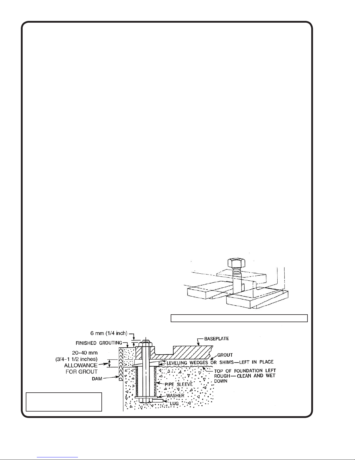
Foundation bolts, of the proper size, should be imbedded
in the concrete. A pipe sleeve, about 2½” diameters larger
than the bolt, should be used to allow for fi nal positioning
of the bolts. See Figure 1.
Position unit on foundation and level using rectangular
metal blocks and shims, or wedges having a small taper as
shown in Figure 2.
2. PIPING
A foot valve and strainer must be installed on the lower
end of the suction pipe to keep pump completely fi lled with
liquid when the pump is used under suction lift conditions.
Connect suction pipe to pump, making certain that all
connections are airtight. When a foot valve and strainer
are used, it is necessary to install a check valve in the
discharge line near the pump to prevent possible casing
damage due to line shock or surge when the pump stops.
A gate valve should also be installed in the discharge line.
Connect discharge pipe to pump casing.
SERVICE CENTERS:
For the location of the nearest Deming Service Center,
check your Deming representative or
Crane Pumps & Systems Service Department in Piqua,
Ohio, telephone (937) 778-8947 or
Crane Pumps & Systems Canada, Inc., Bramton, Ontario,
(905) 457-6223.
Figure 1. Foundation Bolt
Location and Anchorage
Figure 2. Adjusting Wedges for Mounting
4
It is important that the suction and discharge pipes “line
up” naturally with the pump. Do Not “pull” pipes into
position with fl ange bolts or fi ttings. Both suction and
discharge pipes must be supported independently near
the pump to eliminate any strain on the pump. Piping
should be arranged with as few bends as possible, and,
preferably, with long radius elbow whenever possible. Turn
shaft to see that it rotates freely. If rotor binds, it indicates
a strain on the casing, which must be corrected before
operating pump. It may be necessary to shim motor at
foundation to assist piping connection line-up.
3. WIRING / ROTATION
Check motor name plate for electrical characteristics. Be
sure they are the same as the rating of the electric power
available. Connect power lines to motor in accordance with
the wiring diagram on the motor. Test rotation by jogging
motor. Shaft must rotate in the direction indicated by arrow
cast on pump casing.
C - OPERATION
1. STARTING THE PUMP
The following important items should be checked before
starting.
a. Pump and driver securely bolted
b. Piping complete
c. Motor properly lubricated. Follow the recommendations
found in the Maintenance Section
d. Open the seal fl ush valve, if used
e. Shaft turns freely
f. Rotation is correct. The pump must rotate in the
direction of the arrow on the casing.
g. Discharge valve. A high or medium head centrifugal
pump operating at full speed with the discharge valve
closed, requires much less power than when operating
at its rated head and capacity with the discharge valve
open.
For this reason, it is usually best to have the discharge
valve only partially open when starting the pump.
WARNING! - Operating the pump with a closed
or partially open discharge valve can result in
excessive heat buildup. Such operation should
be limited to the shortest pratical duration.
Operating the pump at or near shut-off head places
greater loads on the shaft and motor than operation at
the designed fl ow rate and head.
2. PRIMING
CAUTION: Before starting the pump, the casing and
suction line must be fi lled with liquid, and air-vented
through the vent pipe plugs. The pump must not be run
until it is completely fi lled with liquid, because of danger of
injuring some of the parts of the pump which depend upon
liquid for lubrication.
The discharge gate vale should be closed during priming.
Be sure the mechanical seal and power frame are supplied
with the proper lubrication.
See LUBRICATION.
PRIMING BY SUCTION PRESSURE
When operating with suction pressure (fl ooded suction),
remove the pipe plug at the top of the casing and when
pump is fi lled with liquid, replace plug.
PRIMlNG WITH FOOT VALVE AND STRAINER
A foot valve and strainer may be installed on the lower end of
the suction pipe to keep pump fi lled with liquid. Incorporate
fi ller pipe in discharge pipe between pump and check valve.
Remove pipe plug at top of casing, then fi ll suction pipe and
pump with liquid. When pump is full of liquid, replace plug
and close fi ller pipe.
CAUTION: When a foot valve and strainer are in stalled on
the suction pipe, a spring loaded type check valve MUST be
installed next to the pump in the discharge piping to prevent
pump rupture from water hammer shock.
Priming by means of primer pump or ejector, attached to
the pump, will also remove air from suction pipe and pump
casing. When pump is fi lled with liquid, start motor and
slowly open discharge gate valve.
3. STARTING
Start the pump. When the pump has reached its designed
operating speed slowly open the discharge valve to obtain
the desired capacity and pressure.
With the pump running, carefully check for unusual
vibration, quite operation, mechanical seal function and
unusually high temperature.
WARNING! - NEVER try to adjust or work on
the pump while it is running. Always stop
the unit completely before attempting any
adjustment.
h. Suction valve, if used, must be fully open. Do not use
suction valve as a throttling device.
i. Pump fully primed
Only after these items have been checked should the
pump be started.
5
 Loading...